1
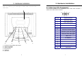
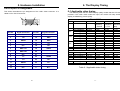
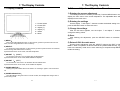
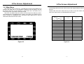
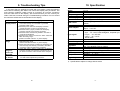
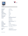
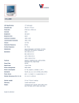
Table of Contents
1. Caution and Warning …………………………………………… 2
2. FCC Requirements ……………………………………………... 3
3. Product Safety Precautions …………………………………… 4
4. Introduction ………………………………………………………. 5
5. Hardware Installation ……………………………………………
5-1 Unpacking ……………………………………………………..
5-2 Installation …………………………………………………….
5-3 Video Input Pin Assignment ……………………………….
6
6
6
9
6. The Display Timing …………………………………………….. 11
6-1 Applicable video timing …………………………………… 11
7. The Display Controls ………………………………………….. 12
7-1 Display Controls ……………………………………………. 12
7-2 Screen Adjustment Operation Procedure ……………… 13
8.The Screen Adjustment ………………………………………… 14
8-1 Main Menu ……………………………………………………. 14
8-2 How to use AUTO CONFIG …………………………………19
9. Troubleshooting Tips ………………………………………….. 20
10. Specification …………………………………………………… 21
11. Appendix…...…………………………………………………… 22
11.1 Safety Guidelines ...........................................................22
11.2 Compliance Information for U.S.A.................................24
11.3 CE Conformity for Europe .............................................24
12. DECLARATIONOF CONFORMITY …..……………………… 25
0
1
E
N
G
L
I
S
H
D
E
U
T
S
C
H
F
R
A
N
Ç
A
I
S
E
S
P
A
Ñ
O
L
I
T
A
L
I
A
N
1. Caution and Warning
2. FCC Requirements
“ This device complies with part 15 of the FCC Rules. Operation is subject to the
following two conditions: (1) This device may not cause harmful interference, and (2) this
CAUTION !!
RISK OF ELECTRIC SHOCK
DO NOT OPEN
device must accept any interference received, including interference that may cause
undesired operation.“
The equipment has been tested and found to comply with the limits for a Class B digital
device, pursuant to part 15 of FCC rules. These limits are designed to provide reasonable
CAUTION: To reduce the risk of electric shock, do not
remove cover (or back).
No user serviceable parts inside.
Refer servicing to qualified personnel
protection against harmful interference in a residential installation. This equipment
generates, uses and can radiate radio frequency energy and, if not installed and used in
strict accordance with the instructions, may cause harmful interference to radio
communications. However, there is no guarantee that interference will not occur in a
particular installation. If this equipment does cause harmful interference to radio or
television reception, which can be determined by turning the equipment off and on, the user
is encouraged to try to correct the interference by one or more of the following measure:
WARNING:
- Reorient or relocate the receiving antenna.
TO PREVENT FIRE OR SHOCK HAZARD, DO NOT EXPOSE THIS MONITOR
TO RAIN OR MOISTURE.
- Consult the dealer or an experienced radio/TV technician for help.
“HIGH VOLTAGE EXISTS ON THE BACK LIGHT POWER LEAD OF THIS
MONITOR. BEFORE SERVICING, DETERMINE THE PRESENCE OF HIGH
VOLTAGE BY CONNECTING THE H.V. METER BETWEEN THE BACK LIGHT
POWER LEAD AND CHASSIS ONLY.“
- Increase the separation between the equipment and the receiver.
- Connect the equipment into an outlet on a circuit different from that to which the
receiver is connected.
Shielded interconnected cables and shield power cords must be employed with this
equipment to insure compliance with the pertinent RFD emission limits governing this
device.
Changes or modifications no expressly approved by the manufacturer could void the user
authority to operate the equipment.
Notice of Compliance with Canadian Interference-causing Equipment Regulations
This Class B digital apparatus meets all requirements of the Canadian InterferenceCausing Equipment Regulations.
Cet appareil numique de la Classe B respecte toutes les exigences du Rlement sur le
matiel brouilleur du Canada.
2
3
E
N
G
L
I
S
H
D
E
U
T
S
C
H
F
R
A
N
Ç
A
I
S
E
S
P
A
Ñ
O
L
I
T
A
L
I
A
N
3. Product Safety Precautions
Follow all warnings and instructions marked on the product.
Do not use this product near water.
This display should be installed on a solid horizontal base.
When cleaning, use only a neutral detergent cleaner with a soft damp cloth. Do not spray
with liquid or aerosol cleaners.
4. Introduction
Welcome to enjoy the fantastic sightseeing world. This new technology will
bring you the whole new feeling about the “monitor”. We show here some of the
major advantages of the LCD monitor. You will really find some other advantages
when you use it.
1. The character of low radiation and less flicker reduce the probability of harm
for your health compared to traditional CRT monitor.
cabinet and other parts.
2. The LCD monitor weights only 7.5 Kg, and its compact size requires only
minimal desktop space. These two merits make this monitor easier to be
transported and can be used in nearly any environmental.
Adequate ventilation must be maintained to ensure reliable and continued operation and to
3. The LCD monitor operates on low power consumption level offering savings
on power bills and the earth resources.
Do not expose this display to direct sunlight or heat. Hot air may cause damage to the
protect the display from overheating. Do not block ventilation slots and openings with
objects or install the display in a place where ventilation may be hindered.
4. The special design of the LCD cabinet is both attractive and ergonomic.
This display should be operated from the type of power source indicated on the AC/DC
5. The usage of the LCD monitor is the same as the CRT monitor. There is no
need to change the hardware of your computer, just plug and play..
adapter.
Do not install this display near a motor or transformer where strong magnetism is
generated. Images on the display will become distorted and the color irregular.
6. Building two 3 Watts speakers multimedia system.
Do not allow metal pieces or objects of any kind fall into the display from ventilation holes.
to dangerous voltage or other risks. Refer all servicing to qualified service personnel.
Unplug this product from the wall outlet and refer servicing to qualified service personnel in
the event that:
Liquid is spilled into the product or the product is exposed to rain or water.
2.
The product does not operate normally when the operating instructions are followed.
3.
The product has been dropped or the cabinet has been damaged.
4.
The product exhibits a distinct change in performance, indicating a need for service.
5.
Power cord or plug is damaged or frayed.
4
D
E
U
T
S
C
H
F
R
A
N
Ç
A
I
S
E
S
P
A
Ñ
O
L
Do not attempt to service this unit yourself. Removal of the display cover may expose you
1.
E
N
G
L
I
S
H
I
T
A
L
I
A
N
5
5. Hardware Installation
This chapter will guide you the correct installation procedures of your LCD
monitor.
1. Turn power off both Computer and Display before making any connection.
2. Install Display on the solid horizontal surface such as a table or desk.
5-1. Unpacking
After you unpack your LCD Monitor, please make sure that the following items
are included in the carton and in good condition. If you find that any of these items
are damaged or missing, please contact your dealer immediately.
•
•
•
•
•
•
5. Hardware Installation
One LCD Monitor mounted on its stand
15-pin D-sub Video cable
Audio cable
AC/DC adapter with 12V DC output
AC power cord
The user manual
5-2. Installation
This analog LCD display DOES NOT require any special drivers. Necessary
drivers are supplied by the video card manufacturer and may be found on the
diskettes supplied with the video card that came with your computer. “Windows”
drivers for both the display and the video card are supplied on the “Windows” CD
or diskettes. Unfortunately, Microsoft did not provide a complete listing of the
displays on the initial retail release. You may use the standard SXGA (1280X1024
@60Hz) as the display type. The video card must also be set up correctly in
“Windows” and make sure the video output of the VGA card is on list in Section
6.1 or check your Video Card manual or “Windows” Read me file for further
information on Video Card. After the question listed above is solved, we continue
the setup procedure as below.
3. Connect the power cable and the AC/DC adapter, then connect adapter to the
back of the LCD monitor.
4. The LCD monitor comes with a 15-pin to 15-pin video cable, you may use
this cable for both IBM PC’s & compatibles and Macintosh.
IBM PC’s & COMPATIBLES
Use of the 15-pin to 15-pin connector cable: Connect one end of the signal
cable to the 15-pin connector to the rear of the Display; and the other end to the
15-pin connector on the rear of the computer.
APPLE/MACINTOSH
Use of the 15-pin to 15-pin connector cable: Connect one end of the signal
cable to the 15-pin connector on the rear of the Display; connect a MAC adapter
to the video connector on the rear of the Apple/Macintosh computer. Then, plug
the other end of the signal cable into the MAC adapter. (Contact your local
Apple dealer for information on purchasing the correct conversion connector.)
5. Tighten the screws of the Display cable until the connectors are fastened
securely.
6. Switch on power to the Computer system, then to the monitor.
NOTE: The word “Windows” in this user guide refers to the following Microsoft
operating systems: Windows ‘95, Windows NT, Windows ‘98, Windows 2000, Windows
Me (Millennium), and Windows XP.
6
E
N
G
L
I
S
H
D
E
U
T
S
C
H
F
R
A
N
Ç
A
I
S
E
S
P
A
Ñ
O
L
I
T
A
L
I
A
N
7
5. Hardware Installation
5. Hardware Installation
The following picture provides the connection
outline
1
6
5
4
3
1 = Facility for fixing VESA wall bracket
2 = Video IN (D-SUB)
3 = Video IN (DVI-D)
4 = DC power IN
5 = Audio IN
6 = Speakers
8
2
5-3. Video Input Pin Assignment
This section describes the pin assignment of the LCD’s video connector.
called 15 Pin Mini D-sub Connector.
Pin NO.
Signal Connector
1
Red Video Signal
2
Green Video Signal
3
Blue Video Signal
4
N.C.
5
Ground
6
Ground for red video signal
7
Ground for green video signal
8
Ground for blue video signal
9
DDC +5 V
10
PC detection
11
N.C.
12
DDC data
13
Horizontal sync signal
14
Vertical sync signal
15
DDC clock
9
It is
E
N
G
L
I
S
H
D
E
U
T
S
C
H
F
R
A
N
Ç
A
I
S
E
S
P
A
Ñ
O
L
I
T
A
L
I
A
N
5. Hardware Installation
6. The Display Timing
DVI-D Input Pin Assignment
This section describes the pin assignment of the LCD’s video connector. It is
called 24 Pin DVI-D Connector.
9
1
8
6-1 Applicable video timing
The following table lists the better display quality modes that the LCD monitor
provides. If the other video modes are input, the monitor will stop working or
display unsatisfactory picture quality.
VESA MODES
Horizontal
Nominal
Frequency
+/- 0.5KHz
DOS 720*400@70Hz 900*449
31.469
640*480@60Hz 800*525
31.469
VGA 640*480@72Hz 832*520
37.861
640*480@75Hz 840*500
37.500
800*600@56Hz 1024*625 35.156
SVGA 800*600@60Hz 1056*628 37.879
800*600@72Hz 1040*666 48.077
800*600@75Hz 1056*625 46.875
1024*768@60Hz 1344*804 48.363
XGA 1024*768@70Hz 1328*806 56.476
1024*768@75Hz 1312*800 60.023
1152*864@75Hz 1600*900 67.500
SXGA 1280*1024@60Hz 1688*1066 63.981
Mode
19
24
C
Pin NO.
Signal Connector
Pin NO.
Signal Connector
1
T2-
14
DDC POWER
2
T2+
15
GND
3
SGND
16
HPD
4
N.C.
17
T0-
5
N.C.
18
T0+
6
DDC CLK
19
SGND
7
DDC DAT
20
N.C.
8
N.C.
21
N.C.
9
T1-
22
SGND
10
T1+
23
TC+
11
SGND
12
N.C.
13
N.C.
10
24
TC-
C
N.C.
Resolution
Total
Vertical
Nominal
Frequency
+/- 1 Hz
70.087
59.940
72.809
75.000
56.250
60.017
72.188
75.000
60.004
70.069
75.029
75.000
60.020
VCLK
Nominal
Pixel Clock
(MHz)
28.322
25.175
31.500
31.500
36.000
40.000
50.000
49.500
65.000
75.000
78.750
108.00
108.00
70.086
70.087
59.940
72.1
25.175
28.322
25.175
75.000
59.940
74.927
25.175
80.000
IBM MODES
EGA
DOS
VGA
XGA
640*350@70Hz
720*400@70Hz
640*480@60Hz
1024*768@72Hz
800*449
900*449
800*525
1304*798
VGA
XGA
640*480@60Hz 800*525
1024*768@75Hz 1328*804
31.469
31.469
31.469
57.515
MAC MODES
31.469
60.241
Table 6.1 Applicable video timing
11
E
N
G
L
I
S
H
D
E
U
T
S
C
H
F
R
A
N
Ç
A
I
S
E
S
P
A
Ñ
O
L
I
T
A
L
I
A
N
7. The Display Controls
7. The Display Controls
7-2 Screen Adjustment Operation Procedure
7-1 Display Controls
1) Entering the screen adjustment
The setting switches are normally at stand-by. Push the MENU button once to
display the main menu of the screen adjustment. The adjustable items will be
displayed in the main menu.
2) Entering the settings
1 = Power Switch
2 = Power LED
3 = Adjust (4)
4 = Adjust (3)
5 = Select
6 = Menu
Use the Adjust 3 and Adjust 4 buttons to select the desired setting icon and
push the SELECT button to enter sub-menu.
3) Change the settings
After the sub-menu appears, use the Adjust 3 and Adjust 4 buttons to
change the setting values.
4) Save
After finishing the adjustment, push the SELECT button to memorize the
setting.
1) MENU:
Enter to the OSD adjustment menu. It also used for go back to previous menu for submenu, and the change data don’t save to memory.
2) SELECT:
To confirm the current selection. It also used for go back to previous menu for sub-menu,
and the change data will be save to memory.
If pressed when menu is not active, VOLUME is adjusted.
5) Return & Exit the main menu
Exit the screen adjustment, push the ‘SELECT’ button at the ‘EXIT’ of “MISC
MENU”. When no operation is done around 60 sec (default OSD timeout), it goes
back to the stand-by mode and no more switching is accepted except MENU to
restart the setting.
3) ADJUST 4: (RIGHT)
To scroll up in sub menu or to increase value of selected item.
If pressed when menu is not active, BRIGHTNESS is adjusted.
D
E
U
T
S
C
H
F
R
A
N
Ç
A
I
S
E
S
P
A
Ñ
O
L
I
T
A
L
I
A
N
4) ADJUST 3: (LEFT)
To scroll down in sub menu or to decrease value of selected item
If pressed when menu is not active, AUTO CINFIG is adjusted.
5) POWER SWITCH:
Pushing the power switch will turn the monitor on. Pushing it again to turn the monitor
off.
6) POWER INDICATOR:
The LED will light with green color in normal on state, and will light with orange color in
power saving mode.
12
E
N
G
L
I
S
H
13
8.The Screen Adjustment
8-1 Main Menu
The OSD main menu ( Figure 8-1 ) is displayed on screen when MENU key is
pressed. The OSD menu is a combination of graphic and text display. The first
line always shows the current selected or active menu item. The bottom line of
main menu shows information of the input image.
The LEFT and RIGHT keys are used to scroll through items within the menu.
The selected item is highlighted as the scrolling move along. The SELECT key is
used to activate the highlighted item. During this state, MENU key is used to
closed the OSD menu from the screen.
8.The Screen Adjustment
The following table shows the OSD functions that support different video input
sources.
Please make sure which video source you want to use, then select correct
item in the Input Source of OSD Miscellaneous function.
VIDEO
OSD ITEM
INPUT
H-POSITION
V-POSITION
CLOCK
PHASE
AUTO CONFIG
INPUT
INFORMATION
RECALL
AUDIO
COLOR
OSD ADJUST
CONTRAST
BRIGHTNESS
EXIT
Figure 8-1
14
D-SUB
DVI-D
SUPPORT
SUPPORT
SUPPORT
SUPPORT
SUPPORT
SUPPORT
SUPPORT
SUPPORT
SUPPORT
SUPPORT
SUPPORT
SUPPORT
SUPPORT
SUPPORT
NO SUPPORT
NO SUPPORT
NO SUPPORT
NO SUPPORT
NO SUPPORT
SUPPORT
SUPPORT
SUPPORT
SUPPORT
NO SUPPORT
SUPPORT
SUPPORT
SUPPORT
SUPPORT
Figure 8-2
15
E
N
G
L
I
S
H
D
E
U
T
S
C
H
F
R
A
N
Ç
A
I
S
E
S
P
A
Ñ
O
L
I
T
A
L
I
A
N
8.The Screen Adjustment
INPUT
This function is to select the applicable input source, analog input (D-sub), or
Digital input (DVI-D).
The OSD adjusting menu:
H-POSITION:H-Position is used to adjust the horizontal image
position manually. A slider with current value is displayed.
INFORMATION
The “INFORMATION” menu provides the user with detailed information
regarding the current input format and version (include resolution, pixel clock,
vertical /horizontal frequency, software version, and input source).
V-POSITION:V-Position is used to adjust the
vertical image position manually. A slider with current
value is displayed.
RECALL
Recall is used to reload all factory default parameters, if the display is
operating in a factory Preset Timing Mode listed in this user manual.
CLOCK : The item ‘CLOCK’ is used to adjust the number of
clocks(pixels) per line (sample per line). A slider with current value is
displayed.
Audio Adjust
Volume increases the volume, decreases the volume, and mutes the audio.
Balance adjusts the proportion of sound coming from each speaker.
Bass adjusts the low (bass) frequency audio output.
Treble adjusts the high (treble) frequency audio output.
Mute temporarily silences audio output.
PHASE:The item ‘PHASE’ is used to adjust the ADC sample pixel
clock. A slider with current value is displayed. The range of phase adjustment
value is 0 to 100 for 0 to 360 degrees.
AUTO CONFIG (D-SUB input source only)
There are five items:AUTO ADJUST, ATUO TRACKING, AUTO POSITION,
AUTO COLOR and RETURN. Use the Adjust [3] and [4 ] key to scroll up
and down in menu, and then press the SELECT key to start this function. If
the MENU key is pressed, the main menu is re-displayed and nothing is
changed.
AUTO ADJUST : Used to perform automatic configuration of the phase 、
clock、vertical and horizontal position.
AUTO TRACKING:It is used to tune the clock & phase to the best condition
automatically.
AUTO POSITION:It is used to center the image automatically. Both horizontal
and vertical position is adjusted such that the image is centered on the
panel.
•
COLOR
Configure the image color. There are three item : 9300K、 6500K、
USER MODE.
9300K : The item “9300K” is used to default 9300K color temperature.
6500K : The item “6500K” is used to default 6500K color temperature.
USER MODE:
RED:The item “RED” is used to adjust the gain of red channel in ADC.
GREEN:The item “GREEN” is used to adjust the gain of green
channel in ADC.
BLUE:The item “BLUE” is used to adjust the gain of blue channel in ADC.
AUTO COLOR:It is used to adjust the gain and offset of the Red, Green and
Blue channels on the ADC automatically.
RETURN:Go back to main menu.
16
17
E
N
G
L
I
S
H
D
E
U
T
S
C
H
F
R
A
N
Ç
A
I
S
E
S
P
A
Ñ
O
L
I
T
A
L
I
A
N
8.The Screen Adjustment
•
OSD ADJUST
Miscellaneous setting. There are five items:OSD H POSITION、OSD V
POSITION、LANGUAGE & SHARPNESS.
-OSD POSITION:The item is used to setup the OSD menu position. The item
“OSD POSITION” is used to setup the OSD menu position. The OSD
menu horizontal and vertical position is adjusted separately. Each
position adjustment item will bring up the slider window. The maximum
value of the sliders are based on the size of the OSD menu.
-BLACK LEVEL ADJUST: The item “BLACK LEVEL ADJUST” is used to
adjust the black-level
(zero level offset) of the AD converters.
-LANGUAGE: The item is use to select the OSD menu in 5 language.
English, Germany, French, Italian, Spanish
-SHARPNESS:This can adjust the video quality to be sharp or blur.
8-2 How to use AUTO CONFIG Adjustment
This function can tune the parameters of PHASE、CLOCK、H-POSITION
and V-POSITION.
Suggesting Adjustment Steps:
Step 1: Enter the “Windows” Shut-down frame. ( Note:The Wallpaper color
CAN NOT be black.)
Step 2: Enter OSD Main Menu and Choose the “AUTO CONFIG” item, then press
SELECT key. The Picture will auto-adjust by itself. After 4 seconds, you
can exit OSD and Shut-down frame.
Step 3: If you are not still satisfied with the picture quality, you could choose
CONTRAST item in OSD Main Menu and adjust it.
Note:
CONTRAST
The Contrast menu item is used to adjust image contrast.
1. If you don’t like the effect of AUTO CONFIG adjustment, you can adjust
PHASE, CLOCK..… items in OSD.
2. AUTO CONFIG adjustment can be used in “Windows” except black background
frame, but the best effect is in the SHUT DOWN frame.
BRIGHTNESS
Setup the brightness of the panel.
3. It is recommend to run “ EDIT “ program first, then do AUTO CONFIG
adjustment in DOS mode.
Note:
If you don’t press any key during 45 seconds, the OSD will disappear by itself
and not save the parameters.
E
N
G
L
I
S
H
D
E
U
T
S
C
H
F
R
A
N
Ç
A
I
S
E
S
P
A
Ñ
O
L
I
T
A
L
I
A
N
18
19
9. Troubleshooting Tips
In the event that you experience trouble with your Display, check the following
items before contacting the dealer from whom the Display was purchased. The
most common problems usually involve an incorrectly an incorrect connection
from the Video Card to the Display. We recommend that you also consult your
Video Card User’s manual during the Troubleshooting Procedure. Do not exceed
the maximum refresh rate recommended for the display.
Problem
No image on
display screen
Abnormal
image.
Colors of
image on
screen are
abnormal
Disturbances
on Screen
Troubleshooting Tip
1.Check that power cord of the Computer has been
connected securely into wall outlet or grounded
extension cable or strip.
2.Check that power switch of the Display has been
pressed and LED on the front of Display is lit.
3.Check that Video ( Signal ) Cable from the Display
has been securely and correctly connected.
4.Check that Video Card is firmly seated in card slot of
Computer motherboard.
5.Check that the video input from the Video Card falls
within the timing range
(listed in the table of section 6 ) of the Display.
1.Check that the video input from the Video Card falls
within the timing range
( listed in the table of section 6 ) of the Display.
2. Check that Video (Signal ) Cable from the Display has
been securely and correctly connected to the Video
Connector at the rear side of the Computer.
1. Check that Video ( Signal ) Cable from the displays
has been securely and correctly connected to the 15pin Video Connector at the rear side of the computer.
1. OSD adjustment is incorrect. Please consult section 7
for OSD screen adjustment procedures.
10. Specification
Model
Type
LCD panel type
Resolution
Active display area
Pixel dimension
V7 L19
V7 P19S
19.0” TFT
SXGA 1280X1024 Max.
376 mm(H) x 301mm(V)
0.297 mm(H) x 0.297 mm (V)
Auto Config, Brightness, Contrast , Color,
Position
Manual control
Menu, Select, Adjust (3,4), Power.
Input:AC 100 ~ 240V, 50 ~ 60Hz
AC/DC adapter
Output:+12 V DC.
1. D-SUB Video:Analog 0.7 Vp-p. 75 ohms
Sync.:TTL Level, Positive/Negative, Separate Sync.
Input signal
H Sync. :30 ~ 82 KHz
V Sync. :56 ~ 75 Hz
2. DVI-D Video
3 W *2
Multimedia
Power Management YES
15 Pin D-Sub; 24 Pin DVI-D.
Input connector
Safety:CSA, CE, TÜV/GS
Regulation
EMI:FCC-B,MPRII,TCO-03 (option)
480 mm(W) x 458 mm(H)x 210 mm(D).
Dimensions
7.5 Kgs. ( LCD Module only )
Weight
VGA cable, AC / DC adapter, power cord.
Accessory
Operation : 0 ~ 40°C
Temperature
Storage :-20 ~ 60°C
DDC 2B
Plug & Play
OSD control
※ : Specifications subject to change without notice
20
21
E
N
G
L
I
S
H
D
E
U
T
S
C
H
F
R
A
N
Ç
A
I
S
E
S
P
A
Ñ
O
L
I
T
A
L
I
A
N
11. Appendix
For European Countries
In Europe you must use a cord set which is appropriate for the receptacles in
your country. The cord set is HAR-Certified, and a special mark that will appear
on the outer sheath, or on the insulation of one of the inner conductors.
11-1 Safety Guidelines
Warning:This device must be operated with the original power supply.
CAUTION:The socket-outlet should be installed near the equipment
and should be easily accessible.
CAUTION:Use a power cable that is properly ground. Always use the
appropriate AC cord that is certified for the individual country.
Some examples are listed below:
USA…………UL
Canada……..CSA
Germany……VDE
Switzerland…….SEV
Britain…….BASE/BS
Japan…….Electric Appliance Control Act
IMPORTANT NOTICE CONCERNING POWER CORD SELECTION
The power cord set for this unit has been enclosed and been selected
according to the country of destination and must be used to prevent electric
shock. Use the following guidelines if it is necessary to replace the original cord
set, or if the cord set is not enclosed.
The female receptacle of the cord set must meet IEC-60320 requirements
and may look like (Figure A1 below):
In the United States and Canada the male plug is a NEMA5-15 style (Figure A2), UL
Listed, and CSA Labeled. For units which are mounted on a desk or table, type SVT or
SJT cord sets may be used. For units which sit on the floor, only
SJT type cord sets may be used. The cord set must be selected according to the current
rating for your unit. Please consult the table below for the selection criteria for power
cords used in the United States and Canada.
SJT
SVT
Size of Conductors in Cord
Maximum Current Rating of Unit
18 AWG
16 AWG
14 AWG
18 AWG
17 AWG
10 Amps
12 Amps
12 Amps
10 Amps
12 Amps
22
FOR YOUR SAFETY PLEASE READ THE FOLLOWING TEXT CAREFULLY.
IF THE FITTED MOULDED PLUG IS UNSUITABLE FOR THE SOCKET OUTLETTHEN
THE PLUG SHOULD BE CUT OFF AND DISPOSED OF SAFELY.
THERE IS A DANGER OF SEVERE ELECTRICAL SHOCK IF THE CUT OFF
PLUG IS INSERTED INTO AN APPROPRIATE SOCKET.
If a new plug is to be fitted, please observe the wiring code as shown below.
If in any doubt, please consult a qualified electrician.
WARNING:THIS APPLIANCE MUST BE EARTHED.
IMPORTANT: The wires in this mains lead are coloured in accordance with
the following code:
Green-and-Yellow:Earth
Blue:Neutral
Brown:Live
If the coloured wires of the mains lead of this appliance do not correspond
with the coloured markings identifying the terminals in your plug,
proceed as follows:
Figure A2
Figure A1
For the United States and Canada
Code Type
AC PLUG CORD PRECAUTIONS FOR THE UNITED KINGDOM
The wire which is coloured GREEN-AND-YELLOW must be connected to
the terminal in the plug which is marked by the letter E or by the Earth symbol
or coloured GREEN or GREEN-AND-YELLOW.
The wire which is coloured BLUE must be connected to the terminal in the
plug which is marked with the letter N or coloured BLACK. The wire which is
coloured BROWN must be connected to the terminal in the plug which is
marked with the letter L or coloured RED.
If you have any questions concerning which proper power cord to use, please
consult with the dealer from whom you have purchased the product.
23
E
N
G
L
I
S
H
D
E
U
T
S
C
H
F
R
A
N
Ç
A
I
S
E
S
P
A
Ñ
O
L
I
T
A
L
I
A
N
11-2 Compliance Information for U.S.A.
The equipment has been tested and found to comply with the limits for a
Class B digital device, pursuant to part 15 of the FCC Rules, These limits
are designed to provide reasonable protection against harmful interference
in a residential installation. This equipment generates, uses, and can radiate
radio frequency energy, and if not installed and used in accordance with the
instructions, may cause harmful interference to radio communications.
However, there is no guarantee that interference will not occur in a
Particular installation. If this equipment does cause harmful interference to
radio or television reception, which can be determined by turning the
equipment off and on, the user is encouraged to try to correct the
interference by one or more of the following measures:
• Reorient or relocate the receiving antenna.
• Increase the separation between the equipment and receiver.
• Connect the equipment into an outlet on a circuit different from that to
which the receiver is connected.
• Consult the dealer or an experienced radio/TV technician for help.
FCC Warning
To assure continued FCC compliance, the user must use ground power
supply cord and the provided shielded video interface cable with bonded
ferrite cores. If a BNC cable is going to be used, use only a shielded BNC(5)
cable. Also, any unauthorized changes or modifications not expressly
approved by the party responsible for compliance could void the user’s
authority to operate this device.
DECLARATION OF CONFORMITY
Importer's Name:
INGRAM MICRO EUROPE AG
Importer's Address: Heisenbergbogen 3
D-85609 Dornach/Aschheim
Germany
Declares, that the products
Product Name: 19-inch color monitor
Model Number: V7 L19 Series
Part Number : V7 P19S
Confirm to the following product specifications:
Safety: IEC950: 1991+A1, A2, A3,A4,A11/EN60950: 1992+A1, A2
A3,A4+A11
EMC : EN55022: 1998 -Class B
EN50082-1: 1992 -General immunity
EN61000-3-2: 1995/A1/A2:1998
EN61000-3-3: 1995
FCC title 47 CFR, Part 15 Class B / ICES-003 Issue 2
Supplementary information:
The products herewith comply with the requirements of the following Directive
and carry the CE marking accordingly:
- The EMC Directive 89/336/EEC (including 93/68/EEC)
- The low voltage Directive 73/23/EEC (including 93/68/EEC)
These Devices comply with part 15 of the FCC Rules. Operation is subject to
the following two conditions: (1) the devices may not cause harmful interference
and (2) the devices must accept any interference received, including
interference that may cause undesired operation.
11-3 CE Conformity for Europe
The device complies with the requirements of the
ECC directive 89/336/EEC as amended by
92/31/EEC and 93/68/EEC Art.5 with regard to
“Electromagnetic compatibility”, and 73/23/EEC as
amended by 93/68/EEC Art.13 with regard to
“Safety”.
24
Ingram Micro Europe AG
For Regulatory compliance information only, contact:
INGRAM MICRO EUROPE AG
Heisenbergbogen 3
D-85609 Dornach/Aschheim
Germany
25
E
N
G
L
I
S
H
D
E
U
T
S
C
H
F
R
A
N
Ç
A
I
S
E
S
P
A
Ñ
O
L
I
T
A
L
I
A
N
V7 VIDEOSEVEN Monitor Warranty Conditions
V7 VIDEOSEVEN monitors (CRTs) are delivered with a 36-month on-site exchange warranty in accordance
with the following conditions.
1. Extent of Warranty
The warranty begins on the date of purchase at your specialty retailer. It applies to the device and all of its
components. The warranty applies only to V7 VIDEOSEVEN monitors for which a 36-month warranty with onsite exchange service has been expressly stated. All LCD monitors are excluded, as are similar V7
VIDEOSEVEN products for which no express warranty with on-site exchange service is offered. V7
VIDEOSEVEN LCD monitors are offered with a 36-month warranty (sometimes including backlight and panel –
depending on the model). No on-site exchange service applies to all LCD monitors, but rather either Bring-In or
Pick-Up service (depending on model).
On-site Exchange Service includes that, on instructions from INGRAM MACROTRON Distribution
GmbH, a different, repaired and refurbished substitute device with the same or better technical
specifications will be sent to the purchaser, and at the same time the defective monitor with the reported
serial number will be picked up. The customer has no right to a substitute device without returning the
defective device. If the customer should not be present at the appointment time agreed upon with the
service provider commissioned by Ingram Macrotron, the right to on-site exchange shall lapse. In this case,
the customer must bear the cost of a new exchange at a new date.
Pick-Up Service includes that the defective LCD monitor is picked up from the customer and then repaired
at our service department. The customer receives the same device back after repair (if it is still repairable,
otherwise, an equivalent or higher-value device).
Bring-In Service includes that the defective LCD Monitor is sent by the customer to the repair center
commissioned by Ingram Macrotron, repaired there (if it is still repairable, otherwise an equivalent or
higher-value device will be provided), and then returned to the customer from the repair center. In this case,
shipping costs to the repair center are the responsibility of the customer, and return costs are the
responsibility of Ingram Macrotron.
Exchange or repair does not cause any extension of the warranty period. Additional claims are excluded,
particularly claims to cancellation of the contract, price reduction, or compensation for damages. This
warranty only applies to the original purchaser of the device at a specialty dealer and is not transferable.
2. Procedure/Required Documentation
Retail customers report their breakdown to the Service Partner of INGRAM MACROTRON Distribution GmbH
using the following hotline number and country extension.
German
English
English
French
Italian
Spanish, Portuguese
+ 49-700-555-333 -11
-12
-13
-14
-15
-16
The service department needs the following information:
Serial number
Precise product designation
Invoice and/or delivery note number
Copy of the purchase invoice
Exact description of defect
3. Warranty services are excluded for the following causes of damage:
a) Neglect, improper use, or abuse, including but not limited to improper mechanical or electrical use, or
operation outside of the stated operating conditions.
b) Adjustment, repair, or modification by personnel not authorized to do so by INGRAM MACROTRON
DISTRIBUTION GmbH.
c) Unsuitable operating conditions, excessive or insufficient heating or cooling, or power failures, power
surges, or other irregularities.
d) Damage arising from non-compliance with the operating manual, e.g., connection to improper mains
voltage or current type, and damage arising from negligent treatment or abuse.
e) Accidents or acts of God, including but not limited to earthquake, fire, flood, water, storms, and lightning
strikes, or
f)
If the serial number is illegible or has been removed.
4. Costs
The purchaser shall assume all costs incurred by INGRAM MACROTRON Distribution GmbH or the
contractual partners of INGRAM MACROTRON Distribution GmbH when a source of damage pursuant to No.
3 above is determined, or when no defect in the device can be established.
5. Performance
INGRAM MACROTRON Distribution GmbH’s performance within the framework of the on-site exchange
warranty is limited to the exchange of the defective device for a repaired device with a refurbished housing, but
without accessories. The extent of the refurbishment of a defective device is the responsibility of INGRAM
MACROTRON Distribution GmbH or the service partner commissioned by Ingram Macrotron. No legal claims
against INGRAM MACROTRON Distribution GmbH can be asserted with regard to the extent of refurbishment
of a substitute device, except for the functionality and technical specifications of the substitute device.
6. Legal Rights
This warranty does not impair the purchaser’s legal rights: However, to the extent permissible by law, INGRAM
MACROTRON Distribution GmbH hereby excludes any liability for compensation for physical damage, indirect
damage, expenses arising in the fulfillment of contracts, or consequential damages or losses.
7. Applicability
Warranty processing can only take place from the country in which the monitors were originally sold.
8. The Transportation
For clarity on transport damage liability we require you the follow bellow instructions. For Transport only use
the original packaging along with its Styrofoam or original / membrane packaging provided by the service
provider. In the case of transport damage in which the unit was not packed in original carton V7 Videoseven, its
service provider nor the transport company will take responsibility. In order to avoid we would like to request
you to do the following: Ask the service provider to send you an original carton / membrane packaging freight
collect.
9. Scope of Warranty coverage
V7 does not take any responsibility nor warrants any guaranty for consequential damages or coasts resulting
though a defect unit or an install software or a customer misuses. Compatibility problems related to the software
delivered by V7 displays can not be claimed to V7.
10. Warranty condition
All of the about conditions are independent from each other’s validity. The warranty conditions of V7 Displays
are subject to change without prior notice. Fallacies in the warranty conditions can not be claimed at V7.
After the information is checked, the customer will receive a claim number. The service provider commissioned
by Ingram Macrotron makes an appointment with the customer to pick up the monitor. If the customer is not
present at the agreed-upon time, the right to pick-up lapses and the customer is required to bear the costs for
repair and transportation at the next contact. Missing documentation and missing information lead to delays and
costs that arise in connection with them will be charged to the customer as necessary. The Pick-up-Swap-Service
applies to the models L15E, L15EM, L17EM, L17EB, L19EM. This service requires that the unit will be picked
up from the customer and sent to the service provider for a check up. In the case the unit is defect and without
any visible damages, a refurbished unit will immediately be sent to the customer. If the unit claimed as faulty has
no defects the unit will be returned to the customer at an equivalent of 30€ for handling charges. If the unit has
visible damages which are detected during check up the same unit will be repaired and returned free of charge to
the customer.At the event of reselling a Videoseven Display by a non authorized V7 dealer the warranty
conditions will not be valid anymore. The warranty is not transferable and its only valid if sold by a dealer to an
end user. Further requests such as upgrades, credit notes or compensations will not be granted.
26
27
E
N
G
L
I
S
H
D
E
U
T
S
C
H
F
R
A
N
Ç
A
I
S
E
S
P
A
Ñ
O
L
I
T
A
L
I
A
N