1
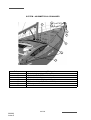
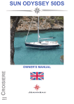
OWNER'S MANUAL
090282
Index G
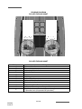
WELCOME ABOARD
Madam, Sir,
You have just taken delivery of your new JEANNEAU boat and we thank you for the
confidence you have shown us in ordering a vessel of our brand. The whole JEANNEAU
team welcomes you aboard.
A JEANNEAU is made to last, in order to bring you all the pleasure you expect from a
vessel over a period of many years. Each boat is subject to the utmost attention to detail
from the design stage right through to launching.
This manual is meant to help you to enjoy your boat comfortably and safely. It includes the
boat specifications, the equipment provided or installed, the systems and tips on her
operation and maintenance. Some of the equipment described in this manual may be
optional.
Your JEANNEAU dealer will be able to help and advise you in the use and maintenance
of your boat.
Read this user's guide/owner's manual carefully and get to know your boat before using it.
The better you know your vessel the more pleasure you will get from being at the helm.
The sea is a source for learning. Caution based on a knowledge of one's own limits and
those of the boat is the pre-requisite for an accomplished sailor.
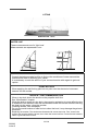
Even when your boat has been adapted for them, the sea and wind conditions
corresponding to the design categories A, B, C and D may vary, ranging from severe
conditions to strong storms subject to the risks of exceptional waves and gusts of wind, this
meaning they are dangerous conditions in which only an experienced, fit and well trained
crew manoeuvring a well maintained boat can sail in a satisfactory manner.
This user's guide/owner's manual is not a course in safety at sea or about sailing sense. If
this is your first boat or if you change to a new type of boat which you are not used to, get
some training in boat control and sailing to ensure your safety and comfort. Your dealer,
your international sailing association or your yacht club will be very happy to recommend
local sailing schools or professional instructors.
Make sure the sea and wind conditions will correspond to the category of your boat and
you and your crew are able to handle the boat in these conditions.
Always listen to the weather forecast before you put out to sea.
Keep this user's guide/owner's manual in a safe place and hand it over to the new owner
if you sell your boat.
You are advised to keep all the instructions and manuals provided by the boat
equipment manufacturers (accessories...) in the same place as this manual.
-1/166
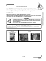
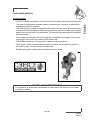
INTRODUCTION
THE USERS OF THE BOAT ARE INFORMED OF THE FOLLOWING:
This user guide/owner's manual is not a maintenance or repair guide. In case of
difficulty do not hesitate to call on the services of your concessionaire JEANNEAU.
Any alterations which may affect the safety specifications of the boat must be
assessed, carried out and recorded by persons qualified to do so. Any change in the
distribution of the vessel's mass (adding a radar, altering the mast, changing an engine,
etc) may affect the stability, trim and performance of your boat.
The SPBI shipyards may not be held responsible for any alterations which they have not
approved.
The complete crew must be equipped appropriately.
In numerous countries, a licence, an authorization or a training course is requested.
Make sure you have this legal authorization before you use your boat.
Adapt the use of your boat to her condition that wears out with time and use.
Any boat, however solid she may be, may be severely damaged if badly used. This is
not compatible with safe navigation. Always adapt the speed and direction of your boat to
the conditions of the sea.
The boat shall not be loaded more with than the maximum load recommended by the
builder, in particular the total weight of the food supplies, of the different equipment that are
not supplied by the builder and of the persons on board.
The weight of the boat shall be properly distributed.
The stability is reduced when you add weight in the upper parts.
In case of heavy weather, the hatches, lockers and doors shall be closed in order to
minimize the risk of water coming in.
Breaking waves are a serious threat to stability.
The water in the bilge shall be kept at its minimum.
The stability may be reduced when you tow a boat or when you lift heavy weights with
the davits or the boom.
If your boat is equipped with a liferaft, carefully read the instructions. The boat must
have on board all the proper safety equipment (lifejackets, buoys, harness, flares, liferafts,
etc.) depending on the type of vessel, its certification, the country, the weather conditions
encountered, etc.
The crew must be familiar with the use of all the safety equipment and the emergency
safety procedures (MOB, towing etc.). Sailing schools organise regular training sessions.
1/166
090282
Index G
Anyone on the deck shall wear a life jacket or a buoyancy aid.
The safety regulations as defined by the sailing code and enforced by the ’’COLREG’’
should be observed.
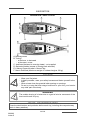
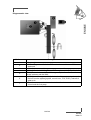
NAME PLATE:
Some of the data is shown on the manufacturer's plate fixed to the boat. The explanation
of the data is given in the appropriate chapters of this manual.
IDENTIFICATION OF VESSEL:
The vessel's identification is found on the builder's certificate delivered with the boat and is
engraved on the starboard aft side.
So as to be able to continuously improve their product the SPBI shipyards reserve the right
to make any alterations in design, layout or equipment which they judge necessary.
That is the reason why the specifications and information given are not contractual, they
may be modified without prior notice or up dates.
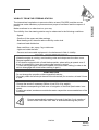
This owner's manual is designed in accordance with the ISO 10240 standard
requirements, it has a general purpose and it may sometimes list some equipment or
accessories or deal with some points or questions that are not relevant to your own boat.
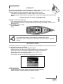
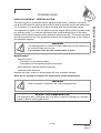
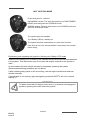
The different warnings used throughout this guide are broken down as follows.
DANGER
Indicates the existence of a serious inherent danger with a high risk of
death or serious injury if the appropriate precautions are not taken.
WARNING
Indicates the existence of a danger which could lead to injury or death if the
appropriate precautions are not taken.
PRECAUTION
Indicates a reminder of safety practice or draws attention to dangerous practices which
could cause injury to persons or damage to the vessel or to its components.
ADVICE - RECOMMENDATION
Indicates a recommendation or advice for carrying out manoeuvres appropriate for the
planned manoeuvres.
2/166
090282
Index G
HISTORY OF UPDATES
•Index A .................................................................................................................. 01/2010
•Index B .................................................................................................................. 02/2010
•Index C .................................................................................................................. 09/2010
•Index D .................................................................................................................. 03/2011
•Index E .................................................................................................................. 08/2012
•Index F................................................................................................................... 01/2014
•Index G .................................................................................................................. 06/2014
3/166
CONTENTS
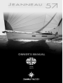
JEANNEAU 57 Anglais
Update 06/2014
Index G
Code: 090282
Total number of pages: 166
INTRODUCTION
Chapter 1 ...... SPECIFICATIONS AND WARRANTY............................................Page 7
Chapter 2 ...... SAFETY ........................................................................................Page 13
Chapter 3 ...... HULL .............................................................................................Page 31
Chapter 4 ...... DECK ............................................................................................Page 35
Chapter 5 ...... STEERING SYSTEM ....................................................................Page 45
Chapter 6 ...... RIGGING AND SAILS...................................................................Page 49
Chapter 7 ...... INTERIOR .....................................................................................Page 69
Chapter 8 ...... WATER AND SEWAGE WATER .................................................Page 77
Chapter 9 ....... ELECTRICAL EQUIPMENT .........................................................Page 91
Chapter 10 .... ENGINE.......................................................................................Page 129
Chapter 11 .... LAUNCHING ...............................................................................Page 157
Chapter 12 .... WINTER STORAGE....................................................................Page 161
PERSONAL NOTES
5/166
1
SPECIFICATIONS AND WARRANTY
TECHNICAL SPECIFICATIONS
CERTIFICATION
DESIGN CATEGORY
YOUR BOAT
7/166
090282
Index G
TECHNICAL SPECIFICATIONS
L.O.A....................................................................................................................... 17.78 m
Hull length............................................................................................................... 17.28 m
L.W.L. ..................................................................................................................... 15.35 m
Overall width ............................................................................................................. 5.00 m
Beam ........................................................................................................................ 5.00 m
Waterline beam......................................................................................................... 4.14 m
Air draught (Version Jib reefer / Performance) - Empty vessel .............................. 24.20 m
Draught Deep draught keel - Maximum.................................................................... 2,50 m
Ballast weight Deep draught keel .......................................................................... 6 100 kg
Draught Shallow draught keel - Maximum................................................................ 2,10 m
Ballast weight shallow draught .............................................................................. 6 500 kg
Light displacement............................................................................................... 21 422 kg
Displacement with maximum load ....................................................................... 27 766 kg
Maximum load recommended by the builder......................................................... 6 344 kg
Including the mass of the persons who are authorized on board (75 kg/165 lbs per adult),
the supplies, the liquids that can be used (fresh water and fuel) in fixed completely full
tanks, the additional loads, the optional equipments, the liferaft and the scope for load.
Total mass of liquids (all tanks full)........................................................................... 1 834 l
Freshwater capacity................................................................................................3 x 310 l
Fuel oil tank capacity ........................................................................................420 l + 310 l
Refrigeration unit capacity ........................................................................................... 300 l
Sewage water capacity (in each bathroom)................................................................... 80 l
Recommended maximum power ............................................................................. 110 kW
Maximum motorisation mass .................................................................................... 265 kg
Battery capacity - Service (24V system)............................................................... 4 x 120 A
Battery capacity - Spare batteries - (24V system) ................................................ 4 x 120 A
Battery capacity - Service (12V system).......................................................................50 A
Battery capacity - Motor................................................................................................60 A
Battery capacity - Bow thruster............................................................................... 4 x 50 A
Battery capacity - Generator.........................................................................................50 A
Cabins.......................................................................................................................... 3/4/5
Architect....................................................................................................Philippe BRIAND
Design.......................................................................................................... Garroni Design
Note: The capacities indicated are maximum (including options).
8/166
090282
Index G
1
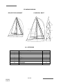
JIB REEFER
PERFORMANCE
Mainsail (classic)...............
Genoa ...............................
Gennaker ..........................
Asymmetrical spinnaker ....
Symmetric spi....................
Staysail..............................
I .........................................
J ........................................
P........................................
E........................................
58 m2
88 m2
170 m2
202 m2
/
46 m2
21,00 m
6,68 m
19,59 m
6,40 m
73 m2
88 m2
170 m2
202 m2
220 m²
46 m2
21,00 m
6,68 m
19,80 m
6,40 m
SPECIFICATIONS AND WARRANTY
SAILS
The sails are the main propulsion means of the JEANNEAU 57
CERTIFICATION
CE Category
A
B
C
D
Persons Maximum
13
14
16
16
DESIGN CATEGORY
Design category
Vessel designed for navigation:
A - "At high sea"
B - "In open sea"
C - "Near to the coast"
D - "In sheltered waters"
(Beaufort scale)
Significant height of waves
to be considered
(in metres H 1/3)
Over 8
Up to and including 8
Up to and including 6
Up to and including 4
Over 4
Up to and including 4
Up to and including 2
Up to and including 0,3
Wind force
The JEANNEAU 57 model conforms to the directive 2003/44/CE.
9/166
090282
Index G
Category A: At high sea
The boat is designed to sail in winds that may exceed Beaufort force 8 and in waves of a
significant height of 4 metres and more.
This craft is largely self-sufficient. Abnormal conditions such as hurricanes are excluded.
Such conditions may be encountered on extended voyages, for example across oceans, or
inshore when unsheltered from the wind and waves for several hundred nautical miles.
Category B: In open sea
The boat is designed to sail in winds not exceeding Beaufort force 8 and in corresponding seas
(waves of a significant height of less than or equal to 4 metres).
Such conditions may be encountered on offshore voyages of sufficient length, or on coastal
waters when unsheltered from the wind and waves for several dozens of nautical miles.
These conditions may also be experienced on inland seas of sufficient size for the wave height
to be generated.
Category C: Near to the coast
The boat is designed to sail in winds not exceeding Beaufort force 6 and in corresponding seas
(waves of a significant height of less than or equal to 2 metres). You may meet with such
conditions in exposed inland waters, in estuaries and in coastal waters with moderate weather
conditions.
Category D: In sheltered waters
The boat is designed to sail in winds that may exceed Beaufort force 4 and in waves of a
significant height of 0,5 metres and more.
Such conditions may be encountered in sheltered inland waters, and in coastal waters in fine
weather.
NOTE:
- The significant wave height is the mean height of the highest one-third of the waves, which
approximately corresponds to the wave height estimated by an experienced observer. Some
waves will be double this height.
- The creation of different design categories results from the need to distinguish between
different levels of risk according to the construction of the boats.
"The parameters for the characteristics are established to define the conditions of navigation
which each category may encounter; they serve purely to evaluate the boat designs and are
not to be used to limit the geographical areas in which these boats may operate".
- One boat may be classed in several design categories at the same time, each with their
different maximum capabilities.
10/166
090282
Index G
YOUR BOAT
1
NAME OF THE BOAT
.............................................................
NAME OF THE OWNER
.............................................................
ADDRESS
.............................................................
.............................................................
.............................................................
HULL NUMBER
.............................................................
SERIAL NUMBER
.............................................................
REGISTRATION NUMBER
.............................................................
DELIVERY DATE
.............................................................
DOOR KEY NUMBER
.............................................................
MAKE OF ENGINE
.............................................................
ENGINE SERIAL NUMBER
.............................................................
ENGINE KEY NUMBER
.............................................................
Your agent
JEANNEAU (Establishment of the company SPBI)
BP 529 - 85505 LES HERBIERS cedex - FRANCE
Tel. (33) 02 51 64 20 20 - Fax (33) 02 51 67 37 65
Internet : http://www.jeanneau.com(fr).
11/166
090282
Index G
SPECIFICATIONS AND WARRANTY
Version
2
SAFETY
SAFETY EQUIPMENT
GENERAL INFORMATION
GAS SYSTEM
RECOMMENDATIONS FOR GAS
FIGHT AGAINST FIRE
BILGE PUMP SYSTEM
EMERGENCY TILLER
13/166
090282
Index G
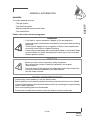
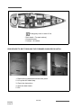
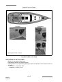
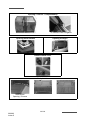
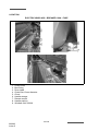
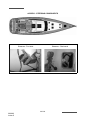
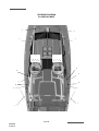
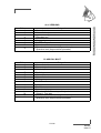
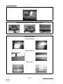
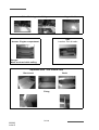
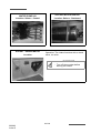
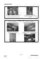
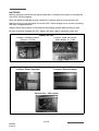
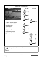
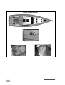
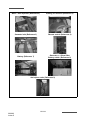
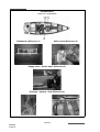
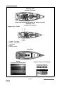
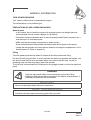
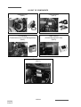
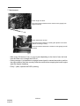
SAFETY EQUIPMENT
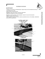
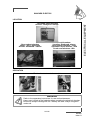
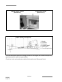
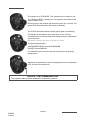
Swimming ladder (means of coming back onboard) (Reference 1)
Opening - Swimming ladder
Swimming ladder in position
Swimming ladder / Garage Open
Note: If over 10 persons on board, 2 liferafts compulsory
Liferaft (Reference 2) - not supplied
14/166
090282
Index G
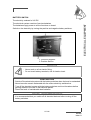
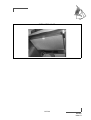
GENERAL INFORMATION
2
DANGERS
The major hazards concern:
SAFETY
- The gas system.
- The electrical system.
- Manoeuvring the vessel and the sails.
- The motorisation.
Please refer to the relevant paragraphs.
DANGER
- Fuel leaks or vapour represent a danger of fire and explosion.
- Leave the engine compartment ventilated for a long time before starting
the engine.
- There may be danger of fire or explosion if direct current systems are
incorrectly used. Refer to chapter Electricity.
- Some boats are equipped with a retractable ladder or removable. Make
sure the ladder is in place and deployed as soon as you are on board.
- Reduce speed in waves.
WARNING
- Before you sail, list the compulsory safety equipment.
- Don't exceed the number of persons indicated in the chapter
'Specifications'.
- The total weight of the persons and equipment must never exceed the
maximum load recommended by the manufacturer.
- Use the seats provided.
ADVICE - RECOMMENDATION
- When sailing, never padlock or lock the liferaft locker.
- Before putting to sea, carefully read the launching instructions shown on the liferaft.
- Close the deck hatches and portholes before each trip (including the companionway
hatch in heavy weather).
- Don't store anything below the floorboards.
- Ensure that movable items are firmly secured when the boat is under way.
15/166
090282
Index G
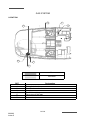
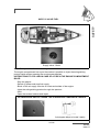
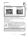
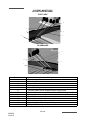
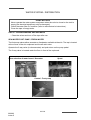
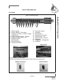
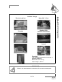
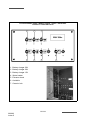
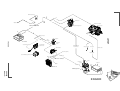
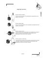
GAS SYSTEM
LOCATION
Gas
Vent hole
REF
1
2
3
4
5
7
Designation
Gas cylinder locker
Gas kill valve on bottle
Gas pipe
Gas rubber tubing
Tap to turn off the gas
Gas vent
16/166
090282
Index G
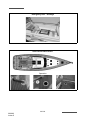
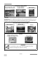
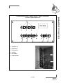
SAFETY
2
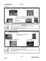
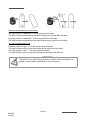
Opening valve / Reheating gas closing
(Reference 1)
REF
6
7
Valve
Designation
Open valve
Closed valve
Gas cylinder locker (Reference 2)
Note: Same position for the other layouts.
17/166
090282
Index G
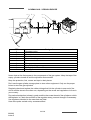
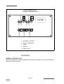
GAS SYSTEM - VERSION US
Schematic diagram
1
4
5
2
6
7
3
REF
1
2
3
4
5
6
7
Designation
Regulator valve 24V
Gas cylinder
Drain
Stuffing box
PVC girdled sleeve
Electromagnetic valve for gas 24V
Pipe Propane Plastic
18/166
090282
Index G
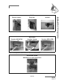
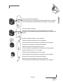
RECOMMENDATIONS FOR GAS
2
Close the valves on the system and on the cylinder when the appliances are not used.
Close the valves before you change cylinders and immediately in case of emergency.
Never leave unattended an appliance that is working. Don't install or store flammable
materials above or over the stove (curtains, papers, napkins etc.).
Make sure that the valves of the appliances are closed before you open the cylinder or
hose valve.
In case you smell gas or find that the burners have gone out (although appliance models
cut off automatically if the flames go out), turn off the valves of the appliances. Do ventilate
the boat in order to get rid of any residual gas. Find the cause of the problem.
Regularly test the gas system in order to detect any gas leak.
Check all the connections using water and soap or detergent, closing the valves of the
appliances and opening the valve on the cylinder.
If you detect a leak, close the valve of the cylinder and repair before you use it again.
The appliances use the oxygen of the cabin and release combustible gases. Ventilate your
boat when using appliances.
Don't obstruct the air vents and at least leave the door open. Don't use the oven or stove
as back up heaters.
Lock the stove oven when being not used in order to avoid damaging the tubes when
sailing..
WARNING
-
For all recommendations concerning gas: Refer to chapter 2, «Safety».
Don't use a solution containing ammonia.
Don't use a flame to detect leaks.
Don't smoke, don't use a naked flame when you change the gas cylinder.
ADVICE - RECOMMENDATION
- Shut off the gas supply at the bottle as well as the cooker tap.
- When changing the cylinder, refit the cap in place on the regulator threaded section
(to avoid corrosion).
- For winter storage instructions and precautions, refer to Chapter 13.
19/166
090282
Index G
SAFETY
Type of cylinder: butane, service pressure 10 kg/cm2 or according to current standards
of your country).
SCHEMA GAS - VERSION EUROPE
4
5
6
7
GAZ
gaz
8
1
9
3
2
REF
1
2
3
4
5
6
7
8
9
Designation
Regulator valve
Gas cylinder
Drain
Connection kit gas bottle
Rubber washers
Pictogram
Connection kit gas copper
PVC girdled sleeve
Gas appliance connection kit
Never obstruct the fast access to the components of the gas system. Keep the taps of the
empty cylinders turned off and the cylinders disconnected.
Keep the protection, lids, covers and taps in their places.
Don't use the gas cylinder storage place to store other equipment. Only use the proper
locker to store the gas cylinders.
Regularly check and replace the rubber tubings that link the cylinder to one end of the
circuit and the stove to the other one, depending on the norms and regulations in force in
your country.
Pay particular attention to keep in good condition the screw thread of the cylinder on which
the regulator is. Check the condition of the regulator every year and change it if necessary.
Use regulators identical to the ones that are fitted.
Have the repairs carried out by someone skilled.
20/166
090282
Index G
2
POSITION OF GAS BOTTLE
SAFETY
The locker for storing gas bottles can be reached through the cockpit. The locker can
accommodate 2 gas bottles. The locker is equipped with bottle fastening straps.
FIGHT AGAINST FIRE
It is the owner's or the skipper's responsibility:
- To have the extinguishers checked in pursuance of the instructions given.
- Use extinguisher replacements with equivalent features (same capacity and fire
resistance) if the ones in place are out of date or have been used.
- To tell the crew:
- where the extinguishers are and how they work,
- where the release aperture is situated in the engine compartment,
- where the emergency exits are.
- Make sure the extinguishers can be reached easily when people are on board.
- Make sure that the ventilation openings in the engine (and generator, if installed)
compartment are well cleared.
Keep the bilge clean. Regularly check that there is no fuel or gas vapour.
For protection of the deck, the vessel owner/user should provide at least one fire bucket
complete with rope in an immediately accessible position.
Do not store combustible materials in the engine compartment.
If non-combustible materials are stored in the engine compartment they must be secured
so there is no danger of them falling on machinery and they do not obstruct access to and
from the compartment.
Exits other than the doors and hatches of the main companionway, equipped with
permanently fitted ladders, are identified with a symbol.
WARNING
- Keep an extinguisher handy in case the fire should start again.
- Fire fighting equipment (portable extinguishers, fire blankets and
buckets) must be permanently and immediately accessible.
21/166
090282
Index G
POSITION OF PORTABLE EXTINGUISHERS (not supplied)
- Aft cabin
- Chart table
- Forward cabin
- Skipper's cabin
- Cockpit locker
22/166
090282
Index G
2
EXTINGUISHERS
An extinguisher and a fire blanket must be placed less than 2 m from any naked flame
appliance.
Extinguishers must be placed less than 5 m from any berth.
It is compulsory for an extinguisher to be placed less than 2 m away from the extinguisher
aperture of the engine compartment.
An extinguisher shall be less than 1 m from the steering station.
The extinguishers must be in position (see "Extinguisher positions" diagram).
Extinguisher, per unit, minimum capacity 5 A/34 B.
For the Jeanneau 57: 25 A/170 B (5 extinguishers of this minimum capacity).
DANGER
- There may be danger of fire or explosion if direct or alternating current
systems are incorrectly used (Refer to chapter Electricity).
WARNING
- Do not obstruct the ways to the emergency exits.
- Do not obstruct the safety controls (fuel oil valves, gas valves, power
switches).
- Do not block the extinguishers placed on shelves.
- Do not leave the vessel unattended when a cooker or heater is in use.
- Do not use gas lamps in the vessel.
- Do not alter the vessel systems (electrical, gas or fuel).
- Do not fill up a tank or change a gas cylinder when an engine is running
or a cooker or heater is on.
- Do not smoke while handling fuels or gas.
WARNING
- The CO² extinguishers shall be used only to fight electrical fires.
- Clear the area immediately after use in order to avoid suffocation.
- Air before entering.
23/166
090282
Index G
SAFETY
The extinguishers are part of the compulsory equipment.
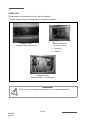
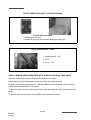
Emergency exits in case of fire
- Deck hatch - Forward cabin(s)
- Companionway
- Portlight - Aft cabins
PROCEDURE TO EXIT THROUGH THE FORWARD CABIN DECK HATCH
1. Remove the mattresses and the deck panel.
2. Lift up the still folded step.
3. Check the obstruction.
4. Open the deck hatch.
5. Exit.
24/166
090282
Index G
2
SAFETY
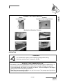
SUPPLY VALVE FUEL
Supply valve - Motor
Note: Same position for the other layouts.
The engine compartment has a port that makes it possible to inject the extinguishing
product inside without opening the usual access hatches.
INSTRUCTIONS TO FOLLOW IN CASE OF A FIRE IN THE ENGINE COMPARTMENT
BILGE:
- Stop the engine.
- Switch off power and stop fuel supply.
- Block off the air supply from the air inlets and outlets of the engine.
- Inject the extinguishing product through the aperture.
- Wait.
- Open the access hatches and repair.
EXTINGUISHER ORIFICE UNDER THE STARBOARD COMPANION LADDER
A pictogram helps to locate it easily
25/166
090282
Index G
MANUAL BILGE PUMP
Location
Operation
Capacity: 40,5 litre / minute.
BILGE PUMP SYSTEM
PROCEDURE TO BE FOLLOWED
- Switch on the electric bilge pump.
- If necessary activate the manual pump.
- Identify the source of the leak by tasting the water and decide on the relevant action to
be taken:
• freshwater = watertank leak.
• seawater = breach of hull.
26/166
090282
Index G
2
ELECTRIC BILGE PUMPS
.
SAFETY
1. Electric bilge pump Capacity: 20 litre / minute
2. Automatic bilge pump Capacity: 110 litre / minute
Location: Forward cabin
Capacity: 70,8 litre / minute
Operation:
The electric bilge pumps are connected to the 12V service circuit. To enable operation
the 12V circuit must be activated by turning on the battery switches.
You can energize the electric bilge pump from the electrical panel.
On the electrical panel - three possible positions : OFF / Automatic / Mechanically
operated.
In the automatic position each pump is set off automatically by a trip switch located in the
sump area or in the bottom of the hull.
MANUAL BILGE PUMP
The manual bilge pump is in the cockpit.
The control arm of the pump shall be kept accessible whatever the circumstances.
WARNING
- The bilge pump system is not designed to provide buoyancy to the boat
in case of damage.
- The bilge pump system is designed to drive out the water being either
sea spray or leaks but absolutely not the water coming through a hole in
the hull, this hole being the result of a damage.
- Do not let the pumps run while dry, this may cause them damage.
- The water in the bilge shall be kept at its minimum.
- Check the functioning of each bilge pump regularly.
SAFETY PRECAUTIONS
- Clean off debris which could block the pump intake points or strainers. If the watertight
partitions which seal off the fore and aft points are fitted with valves they must be
closed at all times and only opened to drain water into the main bilge.
27/166
090282
Index G
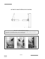
Emergency tiller - Stowage
SECTOR ACCESS PORT
Operation
28/166
090282
Index G
2
EMERGENCY TILLER
To operate the tiller:
- Use a winch handle and unscrew the tiller cover situated at the back of the cockpit.
- Insert the tiller into the rudder stock and make sure it is fully secure in the square.
- If the automatic pilot is connected and is working after the tiller damage, use it.
- Disconnect all apparatus linked to the rudder stock to use the emergency tiller.
ADVICE - RECOMMENDATION
The emergency tiller is designed only to be able to continue underway at a reduced
speed in case of steering gear failure.
29/166
090282
Index G
SAFETY
The emergency tiller is in an aft locker and shall be easy to get to.
3
HULL
MAINTENANCE OF THE HULL
LIFTING
31/166
090282
Index G
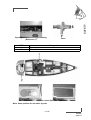
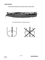
LIFTING
Wetted area: 72 m²
WATER LINE
These measurements are for 'light boat'.
Measurements are expressed in mm.
R50
310
1300
1838
1561
509
2
PRECAUTION
- Consult the harbourmaster's office to find out the conditions of water use and the
maintenance area for cleaning your vessel.
- It is necessary to seek the advice of your concessionnaire with regard to gel-coat
repairs.
PRECAUTION
- When applying the anti-fouling paint do not paint over the electronic instrument
sensors nor the anodes.
ADVICE - RECOMMENDATION
- When in dry dock check the anode on the propeller shaft line.
- See "Motorisation" chapter.
- When the boat is stored at a dry dock, the corrosion protection is not as effective due
to oxidation of the anodes: even the new anodes oxidize the surface. Before returning
the boat into the water, clean the anodes.
- Cleaning anodes: Use sandpaper.
Do not use metal brushes or steel tools to clean the boat, it may damage the galvanic
protection.
- Replacing the anodes: The anodes are fastened with screws and nuts. First, remove the
screws and nuts that hold the anode, then clean the contact surface. Press the new anode to
obtain a good electrical contact.
32/166
090282
Index G
MAINTENANCE OF THE HULL
Preferably wash your boat on shore.
Use as few cleaning agents as possible.
Don't use solvents or aggressive detergent agents. Don't discharge cleaning agents into
the water.
LIFTING
The lower hull of your boat should be covered with an anti-fouling paint which will prevent
the adhesion of marine growth.
The nature of the water in which the boat sails will determine the choice of the anti-fouling
paint as well as the frequency of hull stripping and painting. Do not hesitate to take advice
from your specialists.
Refer to chapter 12 for launching instructions.
PRECAUTION
Before applying anti-fouling paint never:
- Do any sandblasting.
- Use any other solvents than ethylic alcohol.
- Use detergents under pressure.
- Use scrapers.
- Do any sanding other than a light rubbing down by hand with a grade 400 wet
abrasive paper (for the first application).
If cleaning of the anti-fouling paint has to be done with a high pressure hose:
- The water temperature must not exceed 15 °C.
- The water pressure must not exceed 150 bars.
- The distance between the hose nozzle and the hull must not be less than
10 centimetres.
Follow the supplier's instructions very closely when applying the anti-fouling paint.
All these hull maintenance operations can be carried out by your dealer.
33/166
090282
Index G
HULL
3
The materials and equipments of your boat have been selected because of their
high quality and performance and ease of maintenance. However you shall carry
out a minimum maintenance in order to protect your boat from outside attacks (salt, sun,
electrolysis ...).
4
DECK
NAVIGATION
STABILITY
PREVENTION OF MAN OVERBOARD
MOORING LINES
TOWING
MOORING
MAINTENANCE OF THE DECK
35/166
090282
Index G
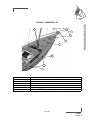
NAVIGATION
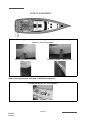
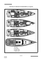
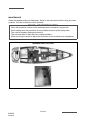
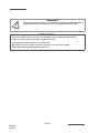
NAVIGATION - DECK LAYOUT
A. Mooring cleats
B. Towing:
- at the bow, to be towed
- at the stern, to tow
C. Jacklines (fastened to mooring cleats) - not supplied
D .Swimming ladder (means of coming back onboard)
E. Lifebuoy support bracket + Mount Flag
F. Mount Outboard (Maximum weight of outboard engine: 20 kg)
DANGER
- Wear your life jacket.
- In heavy weather, wear your safety harness and fasten yourself to the
boat.
- When at sea close the guardrail side-opening or openings.
- Do not try to stop the boat using a boat hook or your foot, your hand or
any other part of the body.
WARNING
The sudden closing of a locker due to a gust of wind or movement of the
boat could result in injury.
ADVICE - RECOMMENDATION
Close the deck hatches and portholes before each trip (including the companionway
hatch in heavy weather).
36/166
090282
Index G
STABILITY
Breaking waves represent a serious danger for stability and for taking in water.
Close the companionway doors and hatches in heavy seas.
During sailing keep all the portholes, windows and doors closed.
- The stability is reduced when you add weight in the upper parts.
- Stability may be reduced when towing a boat or when heavy weights are lifted with the
davits.
PREVENTION OF MAN OVERBOARD
Regularly check the guard-rails:
- With metal guard-rails, watch for corrosion particularly at connecting points.
- With synthetic guard-rails, change them as soon as they show signs of wear due to
chafing or UV.
Areas forbidden when sailing:
- Aft quarterdeck
- Roof
DANGER
It is prohibited to open or leave open the garage while sailing.
Maximum number of persons authorized on the back beach: 5 persons /
400 kg.
MOORING LINES
A sufficient number of mooring lines suitably sized and suitable for the environment shall
be on board for mooring your boat.
- Always manoeuvre your boat using the engine.
- Make allowance for the current and wind when you handle your boat.
- Protect your boat to the highest degree with suitably sized fenders.
- Always keep the mooring ropes unfouled and stored away.
- Handle your boat at a reduced speed.
- Pass warps through the fairleads provided for this purpose.
FAIRLEAD
AFTER MOORING
- Protect the mooring lines against chafing with plastic sleeves.
- Make allowance for the variations in tides if need be.
37/166
090282
Index G
DECK
4
Opening / Closure - Companionway
To maintain fixed navigation
Opening Deck hatches
Opening Portlight
Closure Hatch cover
Cockpit table
Mechanism
Opening / Closure
38/166
090282
Index G
TOWING
- Tow another boat at a reduced speed and as smoothly as you can.
- Pay particular attention when you throw or catch the towing rope (it may foul on the
propeller).
Note: The stability may be reduced when you tow a boat.
TOWED BOAT
Keep steering your boat and see to it that you stay in the wake of the towing boat.
Inappropriate towing can damage your vessel.
MOORING
As a rule, set the anchor in at least 3 times the depth of water.
ANCHORING WITHOUT WINDLASS
- Have your boat pointed into the wind and without speed.
- Pay out the chain while moving back slowly.
- Once the anchor snags, make it fast by reversing slightly.
- Secure the hawser or the chain to the cleat.
ANCHORING WITH ELECTRIC WINDLASS
- Turn on the boat engine.
- Check that the electrical supply of the windlass is switched on (battery switch, circuit
breaker).
- Use the remote control to activate the windlass in lowering mode. Let the chain feed
out by keeping the lowering button on the remote control pressed down.
- Let the chain out while moving backwards slowly and as straight as possible.
- Once the anchor snags, make it fast by reversing slightly.
PRECAUTION
- Before anchoring check the depth of water, the power of the current and the nature of
the sea bed.
- Anchoring manoeuvres with the electric windlass can only be carried out with the
engine running.
WARNING
Windlass operations are dangerous:
- Always keep the anchor chain or rode free and unfouled.
- Always proceed with care, using gloves and always wearing shoes.
- If your boat is equipped with the twin control optional extra, make sure
you use only onecontrol at the same time.
39/166
090282
Index G
DECK
4
TOWING BOAT
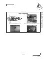
LOCATION
ELECTRIC WINDLASS - BREAKER 120A - FUSE
1.
2.
3.
4.
5.
6.
7.
8.
9.
Chain locker
Bow fitting
Drum head
Chain lifter 12mm diameter
Clinch
Handle storage
Remote control
Handle position
Windlass 24V 2000W
40/166
090282
Index G
4
ANCHORING BY HAND WITH USE OF A MANUAL WINDLASS
- Re-engage the brake and let the anchor hang until the mooring position is reached.
- Have the boat pointed into the wind and without speed.
- Release the brake and pay out the chain slowly.
- Control the speed of anchor lowering using the brake.
- Once the anchor has taken hold re-engage the brake and secure the hawser to the
cleat.
HEAVING UP THE ANCHOR
- Lock the cable lifter snubber.
- Ensure the chain is properly set on the cable lifter.
- Slowly go near the anchor, using your engine (Don't use your windlass to winch the
boat).
- Heave the anchor completely.
- Visually check the last meters till the anchor gets into contact with the davit.
- If you just change berth, check the position of the anchor on the stem fitting.
- For sailing, store the anchor in the chain locker or fasten the anchor to its roller.
- For electrical windlasses cut off the power supply as soon as the anchor has been
lifted.
STERN ANCHORING
Stern anchoring shall be performed with the engine declutched.
- Secure the required length of cablet on the mooring cleat.
- Pay out the anchor line slowly.
- Take care not to damage the propeller or the rudder.
ADVICE - RECOMMENDATION
- After each trip rinse the windlass and anchor chain or rode with fresh water.
- Refer to the manufacturer's instructions for windlass maintenance at the beginning or
end of the season.
- Check the swinging area once the boat is at anchor.
41/166
090282
Index G
DECK
- Release the windlass brake using the handle located in the chain locker so as to
allow the chain lifter to turn freely and to release the anchor from the stem fitting
OPERATION
The windlass is connected to the 24V service batteries.
The boat engine must be running to permit windlass operation
Breaker 120A
Location: Starboard saloon
Battery switch 24V
Location: Saloon
1. - Common
2. + Service
Operation relay
Under the bed - Forward cabin
WARNING
Refer to the manufacturer's instructions for use and maintenance.
42/166
090282
Index G
GARAGE / AFT QUARTERDECK
Alarm
Location: Garage
Control
Location: Port cockpit locker
Mechanism Opening / Closure
OPERATION
DANGER
It is prohibited to open or leave open the garage while sailing.
Maximum working load: 5 persons / 400 kg.
ADVICE - RECOMMENDATION
- Be careful of the open quarterdeck if there is a risk of waves (port or anchoring).: a
wave could hit the quarterdeck from underneath and might damage the system.
- Coming alongside with dinghy: Be careful of waves. There is a danger of the dinghy
getting stuck under the open quarterdeck.
- Make sure that no person or object can get in the way of the garage opening/closing,
particularly the swimming ladder.
43/166
090282
Index G
DECK
4
MAINTENANCE OF THE DECK
Preferably wash your boat on shore.
Use as few cleaning agents as possible.
Don't use solvents or aggressive detergent agents (Refer to chapter 3 "Hull").
Don't discharge cleaning agents into the water.
Regularly brush the deck with a degreasing shampoo and fresh water.
DECK FITTING
- Rinse thoroughly all your equipments with fresh water.
- Periodically lubricate turnbuckles, winches, tracks and travellers with water-repellent
grease. Thoroughly and frequently wash off the pulleys and sheaves with clear water.
SOLID WOOD ON EXTERIOR WOODEN PANELLING
Regularly clean the woodworks with fresh water using a sponge (if need be add some
gentle soap).
PLEXIGLAS
- Rinse plexiglas with fresh water.
- Use a polish paste for thin scratches.
- Consult your dealer concerning deep scratches.
STAINLESS STEEL
Stainless steel is not incorruptible and requires a minimum of upkeep:
- The use of chrome tools is preferable whenever handling stainless steel.
- Re-nourish the protective film regularly with passivation paste (consult your dealer).
EXTERIOR CUSHIONS
Bring the removable cushions inside (washed with soapy water then dried) when the vessel
is unoccupied.
PRECAUTION
- Consult the harbourmaster's office to find out the conditions of water use and the
maintenance area for cleaning your vessel.
- Don't use solvent, alcohol, acetone on plexiglas.
ADVICE - RECOMMENDATION
- Use only products similar to the ones that are included in the maintenance case you
have been delivered with your boat.
- Don't use a pressure washer.
44/166
090282
Index G
5
STEERING SYSTEM
STEERING GEAR
45/166
090282
Index G
STEERING GEAR
5
The steering gear is assembled and pre-adjusted at the factory, however, only actual
use at sea will enable the steering cable to find its definitive postion around the wheel drum.
For this reason, it is necessary to re-adjust the gear after the first few sea outings.
The adjustment is made on the nut and bolt system integral with the steering cable at the
join with the profile. To check the adjustment exert a perpendicular force on the cable
between the wheel drum and the return sheaves located on the hull. The slack in the cable
should not exceed 10 mm. The adjustment is carried out in the same way on the 2 sides of
the cable(see diagram).
WARNING
- The steering system is a feature of sailing safety and for this reason must
be verified at least once a year.
- THE STEERING CABLE MUST BE CHANGED EVERY 4 YEARS.
MAINTENANCE
- Regularly check:
• The tension in the steering cables.
• The tightness of the steering system components.
- Don't tighten the steering cables excessively.
- Lubricate all the elements.
Maintain the nylon, ertalon or teflon bushes with only a suitable lubricant.
Note: Do not hesitate to consult your dealer about system maintenance.
WARNING
- Refer to chapter 2 "Safety"for use of the emergency tiller.
ADVICE - RECOMMENDATION
- The emergency tiller is designed only to be able to continue underway at a reduced
speed in case of steering gear failure.
47/166
090282
Index G
STEERING SYSTEM
CABLE ADJUSTMENT - STEERING SYSTEM
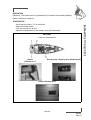
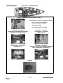
ACCESS - STEERING COMPONENTS
Sheaves - Port side
Sheaves - Starboard
48/166
090282
Index G
6
RIGGING AND SAILS
STANDING RIGGING
RUNNING RIGGING
WINCHES
SETTING THE SAILS
SAILS
49/166
090282
Index G
STANDING RIGGING
ROLLER FURLING MAST
CLASSICAL MAST
ALL VERSIONS
Reference
1
2
3
4
5
6
7
8
Designation
V1
D1
V2
D2
V3D4
D3
Forestay
Backstay
50/166
090282
Index G
Quantity
2
2
2
2
2
2
1
2
STANDING RIGGING
6
MAINTENANCE
Before each trip, carefully inspect the mast from top to bottom.
Periodically check the rigging tightening and the lock nut or pin locking (you should check
it for the first time after a few days sailing in all types of weather).
DANGER
- To hoist a crew member up to the top of the mast, make a bowline with
the halyard directly on the bosun's chair ring (never use the halyard snap
shackle or shackle).
- Do not hoist a crew member when sailing in heavy weather.
ADVICE - RECOMMENDATION
Your dealer JEANNEAU can carry out all maintenance operations or recommend a
skilled specialist to do so.
Backstay - Hydraulic
(optional)
Cable adjustment
Tank - oil
Access
51/166
090282
Index G
RIGGING AND SAILS
Your JEANNEAU dealer was responsible for stepping the mast of your boat.
After masting your vessel and after having sailed for the first time it is necessary to
seek the help of a qualified specialist in order to carry out a rigging check.
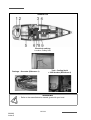
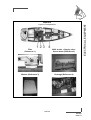
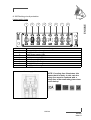
RIGGING DIAGRAM
CLASSICAL MAST
1
8
N
K
L
H
J
I
F
G
E
B
C
A
M
2
D
2
3
3
4
4
5
5
6
6
7
7
52/166
090282
Index G
6
Reference
1
2
3
4
5
6
7
8
RIGGING AND SAILS
ALL VERSIONS
Designation
Genoa furler line
Mainsail sheet
genoa car adjustment
Spinnaker guy
Genoa sheet
SHEET - Staysail
Spinnaker sheet
Spinnaker boom downhaul (Symmetric spi) OR
Spinnaker tack (Asymmetrical spinnaker)
CLASSICAL MAST
Reference
A
B
C
D
E
F
G
H
I
J
K
L
M
N
Designation
Genoa furler line
Genoa halyard
Main halyard
Reef 1
Mainsail foot
Mainsail sheet
Kicking strap
Reef 2
Mainsail sheet
Reef 3
Spinnaker halyard
Spinnaker lift OR Fore stay sail halyard
Halyard - Fore stay
Spinnaker boom downhaul (Symmetric spi) OR
Spinnaker tack (Asymmetrical spinnaker)
53/166
090282
Index G
RIGGING DIAGRAM
K
L
J
/
G
I
H
F
E
C
/
A
B
D
ROLLER FURLING MAST
ROLLER FURLING MAST
Reference
A
B
C
D
E
F
G
H
I
J
K
L
Designation
Genoa furler line
Genoa halyard
Main halyard / Available
Main furling line
Mainsail sheet
Kicking strap
Mainsail sheet
Mainsail foot / Available
Spinnaker halyard
Spinnaker lift OR Fore stay sail halyard
Halyard - Fore stay
Spinnaker boom downhaul (Symmetric spi) OR
Spinnaker tack (Asymmetrical spinnaker)
54/166
090282
Index G
RUNNING RIGGING
Change any distorted or dented sheave. Inspect the pins of the sheaves at the top
of the mast once a year.
Lightly grease the sheave pins.
Regularly check the condition of the jam cleat jaws.
Inspect the halyards for wear and condition.
Regularly clean the pulleys off (old grease, traces of rust) with clear water.
Slightly lubricate the block pins.
Avoid aggressive gybing in order to reduce premature wear on the sheets, attachment
points and the gooseneck.
SYSTEM - MAST FOOT
CLASSICAL MAST
PORT SIDE
1
4
2
5
6
3
7
STARBOARD
10
11
8
12
9
13
55/166
090282
Index G
RIGGING AND SAILS
6
MAINTENANCE
SYSTEM - MAST FOOT
ROLLER FURLING MAST
PORT SIDE
6
1
2
5
3
4
STARBOARD
10
13
8
12
7
Reference
1
2
3
4
5
6
7
8
9
10
11
12
13
Designation
Genoa halyard
Main halyard
Genoa furler line
Kicking strap
Mainsail sheet
Mainsail foot (Classical mast) /
Mainsail safety block stopper (Roller furling mast)
Reef 1 (Classical mast) / Mainsail foot (Roller furling mast)
Mainsail sheet
Reef 3 (Classical mast)
Spinnaker halyard
Reef 2 (Classical mast)
Spinnaker lift OR Fore stay sail halyard
Halyard - Fore stay
56/166
090282
Index G
WINCHES
6
OPERATION
SETTING THE SAILS
CLASSICAL MAINSAIL
With the mainsail being on the deck:
- Screw the pins of the mast sliders for battens into their boxes.
- Slide in the battens through the leech.
- Screw the box cap until you get the required tension (the tightening screw shall not
project beyond the sail).
- Do not forget the small locking screw.
- Put the mainsail into the lazy-bag.
- Fit the mainsail onto its slides, begin with the headboard and finish with the tack.
WARNING
-Refer to the manufacturer's instructions to remove the winches and put
them back.
Improper refitting may result in accidents (e.g. kick of the crank handle).
57/166
090282
Index G
RIGGING AND SAILS
Avoid rope jamming during winch handling. Do not leave loose ropes on the winches but
make them fast on cleats (except on the ’’Self Tailing’’ winches).
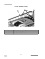
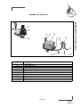
SYSTEM - MAINSAIL (CLASSIC)
2
Reference
1
2
3
Designation
Kicker tackle
Swivel single pulley - 100 mm diameter
Mainsail sheet (D 12mm L 45 m)
58/166
090282
Index G
1
3
6
RIGGING AND SAILS
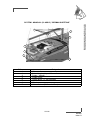
SYSTEM - MAINSAIL (CLASSIC) “GERMAN SHEETING”
2
1
7
5
4
6
3
Reference
1
2
3
4
5
6
7
Designation
Kicker tackle
Swivel single pulley - 100 mm diameter
Pulley - Vertical
Single clutch
Cheek block - 57 mm diameter
Winches
Mainsail sheet (D 12mm L 45 m)
59/166
090282
Index G
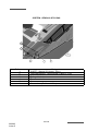
SYSTEM - GENOA & STAYSAIL
2
1
4+5
Reference
1
2
3
4
5
6
6
3
Designation
SHEET - Staysail (D 14mm L 25 m)
Cable adjustment - Genoa sheet (D 8mm L 21 m)
Pulley - Vertical
Traveller - double
Genoa car
Genoa sheet (D 14mm L 35 m)
60/166
090282
Index G
1
6
RIGGING AND SAILS
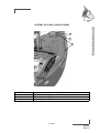
SYSTEM - STAYSAIL TAKE-UP DRUM
1
2
3
Reference
1
2
3
Designation
Staysail take-up drum
Swivel plates - D 10mm
Swivel plates - D 6mm
61/166
090282
Index G
FURLING MAINSAIL
- Remove the hatch giving access to the furling mechanism.
- Spread out the sail on the deck.
- Fasten the head (strap) to the shackle of the upper swivel. Pay attention to the winding
direction.
- Insert the foot adjustment line into the clew block.
- Slowly hoist the sail. Guide the bolt rope (sometimes the groove leading edges may be
insufficiently smoothed off).
- When the sail is up, tack it to the lower shackle.
- Gently sweat up the halyard.
- Refit the hatch.
- Furl the sail facing the wind and keeping a very slight tension on the foot. The mainsail
downhaul and sheet shall be eased off.
ADVICE - RECOMMENDATION
- Carry out the complete maintenance of the winches regularly (before and during the
sailing season).
- Rinse the winches off regularly during the season.
62/166
090282
Index G
6
FURLING GENOA
- Secure the head and halyard to the swivel. Secure the tack to the drum and sheets.
- Have the halyard taut enough but hoist less taut than a sail on a normal stay. Hoist it
until the horizontal creases disappear (Adjust the tension of the luff after a few sea
trips).
- Pull on the line from the cockpit to furl the genoa.
- Before getting under way take advantage of a windless period of time and hoist the
genoa.
- Hand pre-roll the drum to set the furling line on it.
Pay attention to the drum winding direction: The sacrificial strip of the genoa shall be
wrapped outside.
Never force it in case it seizes when you furl or unfurl the head sails. Make sure that no
ropes are caught in the furler.
MAINTENANCE
- Regularly rinse the drum and swivel.
- Lubricate the bearings if recommended by the manufacturer.
- Remove the sails if your boat is not to be used for a long time.
LAZY-BAG: FITTING
- Spread out the lazy-bag on the deck.
- Slide the battens in and close the batten pockets.
- Hank on the lazy-bag until you have the front part about level with the gooseneck.
- Fasten the lazy-bag to the tack with the strap provided.
- Stretch the lazy-bag from the back before you fasten the lazy-jacks.
- Put the mainsail into the lazy-bag.
ADVICE - RECOMMENDATION
-
When you are not sailing, slacken the genoa halyard.
Install the lazy-bag before the mainsail.
When the sail is unfurled, adjust the halyard tightness.
Too much tightness may cause furling problems.
After taking in a reef for the first time mark the halyard position at the clutch (marker
pen or light stitched label)in order to be able to let out the sheet with precision in
subsequent manoeuvres.
63/166
090282
Index G
RIGGING AND SAILS
- Insert the bolt rope into the hole and hoist it and take care that you do not tear it.
AUTOMATIC IN-MAST REEFING BLOCK DIAGRAM
ADVICE - RECOMMENDATION
- At the end of the sailing season, and if possible before winter, leave your sails to a
specialist to have efficient maintenance and repairs.
Reef 1
Reef 2
64/166
090282
Index G
Reef 3
6
RIGGING AND SAILS
SYSTEM - SYMMETRIC SPI
6
2
1
2
2
3
5
2
4
Reference
1
2
3
4
5
6
Designation
Boom
Swivel single pulley - 100 mm diameter
Spinnaker boom downhaul (D 12mm L 30 m)
Spinnaker sheet (D 14mm L 40 m)
Spinnaker guy (D 14mm L 40 m)
Boom lift (D 12mm L 48 m)
65/166
090282
Index G
SYSTEM - ASYMMETRICAL SPINNAKER
1
5
7
6
3
2
1
4
Reference
1
2
3
4
5
6
7
Designation
Swivel single pulley - 100 mm diameter
Spinnaker tack (D 12mm L 18 m)
Tackle block
Spinnaker sheet (D 14mm L 40 m)
Spinnaker halyard (D 12mm L 55 m)
Bobstay
Acorn nut
66/166
090282
Index G
SAILS
6
The working life of a sail mainly depends on its being regularly maintained.
Avoid wear and tear: Use protective items against chafing on the the accessories with
rough surfaces (protective items for spreaders, stanchions etc.).
Have a sail maker's kit and a user's manual so that you may carry out the emergency
repairs waiting for the sailmaker's assistance.
AUTOMATIC REEFING SYSTEM
When you reef down automatically, the mainsail halyard shall not be too loose, otherwise
the reefing blocks take up improper positions.
The diagram shows the path of the automatic reef line and does not indicate the standard
take system.
SHORTENING THE STANDARD MAINSAIL
To shorten sail:
- Head into the wind.
- Slacken off the kick strap.
- Slightly slacken the mainsail sheet.
- Slightly slacken the mainsail halyard.
- Take in the reef line.
- Take up the slack in the mainsail halyard.
- Reset the mainsail sheet.
- Take up the kick strap slack if necessary.
SHORTENING THE FURLING MAINSAIL
To reduce the surface area of the mainsail:
- Gradually take in the mainsail furling line while letting out the foot tack line (keep the
boom perpendicular to the mast).
CLEANING AND MAINTENANCE
Rinse the sails with fresh water from time to time and dry quickly in order to avoid mildew.
Avoid drying the sails to windward when on the mast (when the sails lift, the seams are
worn, the sails may be torn by the rigging).
67/166
090282
Index G
RIGGING AND SAILS
When sailing, trim the sails properly in accordance with the stresses in order to reduce
the harmful strains on the fabric.
HAULING DOWN THE STANDARD MAINSAIL
To haul down the mainsail:
- Haul up.
- Slacken off the kick strap.
- Take up the slack in the Lazy bag ropes.
- Slacken off the mainsail halyard while taking up the reef lines to control the mainsail
descent.
- Fold the mainsail into its lazy-bag.
- Take up the mainsail sheet to immobilise the boom.
- Immobilise the mainsail halyard.
SAIL STORAGE/FOLDING
Avoid storing a wet sail to prevent the appearance of mould and mildew.
Flake the sail parallel to the foot, then roll it up to the bag dimensions.
PROTECTION
UV rays are harmful to polyester and nylon. If the sails remain on the mast, even for 24 h,
protect them with a cover or a protection fabric placed on the leech and foot of the furled
sails.
Our distributor network offers you accessories that have been selected by the yard and are
consistent with your needs.
68/166
090282
Index G
7
INTERIOR
INTRODUCTION
INTERIOR MAINTENANCE
MAINTENANCE OF FABRICS
69/166
090282
Index G
INTRODUCTION
70/166
090282
Index G
INTERIOR MAINTENANCE
7
- Take advantage of the fine weather to take the settee and berth cushions out.
- Put the cushions vertically if you leave the boat for long.
- Use blinds to protect the inside of the boat against UV rays.
- Carefully remove all crumbs.
- Make sure the bilges are clean and dry.
INSIDE VARNISH
- Rinse the inside varnish with fresh water mixed with spot remover and shampoo.
- Polish the interior varnishing with a chamois leather.
MAINTENANCE OF FABRICS
STAIN REMOVAL
- Dab with a clean rag.
- Remove the stain with a solvent poured onto a clean rag. Never pour the solvent
directly over the stain.
- Rub with a clean and dry rag.
- Brush the fabric against the grain.
- Use the vacuum cleaner when the fabric is dry.
PVC OR COATED FABRICS
- Use a sponge and water and soap (household soap type).
ADVICE - RECOMMENDATION
-
Preferably wash your boat on shore.
Use as few cleaning agents as possible.
Don't discharge cleaning agents into the water.
Take the removable upholstery inside when the vessel is not being used.
Place protective covers/awnings.
Mark up each cover and foam when dismantling.
PRECAUTION
- For the PVC fabrics, don't use any solvent or solvent based product (pure alcohol,
acetone, trichloroethylene).
71/166
090282
Index G
INTERIOR
INTERIOR
Armrest - Saloon
Mechanism Opening / Closure - Dining table
Blackout curtain
Companionway
Side portholes
Deck hatch
72/166
090282
Index G
WARNING
Handle the blackout curtains with care.
Do not use the companionway sun visor in strong winds, rain or while
sailing.
100% POLYESTER/DRALON JACQUARD
If you cannot remove the fabric:
- Clean with the vacuum cleaner.
- Clean with a foam for synthetic fabrics (please refer to the product instructions).
If you can remove the fabric:
- Hand wash with an ordinary washing powder at 30° C.
In both cases, dry cleaning is possible. Remove the stains as soon as possible with a damp
rag.
COTTON JACQUARD
- Dry clean.
- Do not iron.
- Do not use hypochlorite.
- Remove the stains with fractionated petrol.
73/166
090282
Index G
INTERIOR
7
Sink + Draining rack - Galley
Vegetable bin
Safe
Location: Port aft cabin
Access - Engine compartment
Danger:
Must be closed while sailing.
Adjustable berth - Port forward cabin
Bench seat
Berth
Fixing
74/166
090282
Index G
INTERIOR
7
Adjustable berth - Starboard forward cabin
Extensions - Bed
Fixing
Cooker
75/166
090282
Index G
8
WATER AND SEWAGE WATER
WATER TANKS
WATER SYSTEM - DISTRIBUTION
WATER SYSTEM - DRAINAGE
SEWAGE
77/166
090282
Index G
WATER TANKS
Location: Saloon
Capacity: 3 x 310l
Gauge
Position / Number of water tanks
WATER TANK
Deck filler
Selection valve - Water tank
Location: Plumbing board
1. Supply - Water tank - Starboard forward
2. Supply - Water tank - Port forward
3. Supply - Water tank - Starboard aft
78/166
090282
Index G
8
OPERATION
In order to prevent any handling mistakes, never fill the water and fuel tanks at the
same time.
Open and close the filler caps with the suitable key.
Check the filler cap seals for condition during filling.
The tanks are fitted with overflow outlets and vents.
Never insert the water filling hose deep down into the system in order to prevent any
over-pressure in the systems.
ADVICE - RECOMMENDATION
- Pay attention to the quality of the water for the filling up. Check if it is drinking water.
- It is possible to sterilize the tanks with a Clonazione tablet (sold at the Chemist's).
- If the boat is not used for long, purify the tanks and pipes with acetic acid (or white
vinegar).
- For winter storage instructions and precautions, refer to Chapter 13.
WARNING
- The tanks' nominal capacity cannot be fully used due to the load and the
need to maintain the correct trim. A 20% reserve should be kept
79/166
090282
Index G
WATER AND SEWAGE WATER
During filling, avoid handling contaminants near the fillers.
220V 60L WATER HEATER
Location: Saloon - Starboard
WATER PUMP 24V
Location: Saloon - Central
SOCKET - SHORE WATER
Location
Operation: The intake functions with a check
valve, no valve.
WARNING
- Turn off shore water before
leaving the vessel.
80/166
090282
Index G
8
WATER AND SEWAGE WATER
PUMP FOR DECK WASHING
Location: Forward cabin
1. Pump for deck washing - 12V
2. Filter
Seawater inlet / Stuffing box
Location: Forward cabin
Connection
Location: Chain locker
81/166
090282
Index G
WATER SYSTEM - DISTRIBUTION
PRECAUTION
- Never operate the water system equipment when the valve is closed or the tank is
empty (the electrical equipment may be damaged).
- Check the water filter for condition (refer to manufacturer's instructions).
- Close the taps of empty tanks.
USE OF THE WASHBASINS AND SHOWERS
- Close the valves and turn off the taps after use.
SEA WATER FOOT PUMP / FRESH WATER
The footpump makes either seawater or freshwater available at the sink. The tap is located
at the corner of the sink cupboard and the aft cabin door.
Operate the 3-way valve (to choose water) and push down on the pump pedal.
The 3-way valve is located under the floor in front of the cupboard.
Valve selection of water board / Sea water
Control - Foot pump
82/166
090282
Index G
Spout
8
WATER AND SEWAGE WATER
DECK SHOWER
WARNING
- Bleed the cockpit shower water system to avoid freezing.
WATER SYSTEM DRAINAGE
OPERATION
Waste water from the sink, washbasins and heads is drained off by thru-hull fittings with
ball valves (the valve is closed when the valve handle is perpendicular to the hose, the
valve is open when the valve handle is in line with the hose).
All the floors have holes (limber holes) for the water flow.
A watertight bilge tray under the engine receives the possible oil leaks.
A main sump located above the ballast receives water from the bilges.
The main sump is partially drained by an electric or a manual pump. Regularly dry the sump
with a sponge.
ADVICE - RECOMMENDATION
- Regularly check the valves and thru-hull seacocks for proper operation and
watertightness.
- Turn off the valves when the water system is not in use.
- Visually check the water pump flow.
- Check the clamps and flexible hose connections for tightness.
- Pay attention to the seals for condition.
- Regularly make sure that the strum box and bilge are perfectly clean.
- Immediately switch off the electric system in case a pump is running while all the water
supplies are turned off.
- In case of a leak check the system.
83/166
090282
Index G
Drainage - Galley sink + Draining rack
Icebox drainage: directly to well.
Drainage - Dishwasher:
Connector to sink drain in kitchen
cabinet.
Drainage - Head
Shower + Washbasin
Port aft head compartment
Shower + Washbasin
Starboard aft head compartment
Shower drainage switch
Drainage - Washer: Starboard saloon
84/166
090282
Index G
SEWAGE
8
USE OF THE MARINE HEADS
To empty the bowl:
- Set the control lever of the pump slantwise (FLUSH).
- Operate the pump.
To dry the bowl:
- Set the lever back vertical (DRY).
- Operate the pump.
To avoid blocking the toilets only use absorbent paper in reasonable quantities.
Schedule a regular rinsing through of the heads with fresh water.
Close the valves after each use (in particular when the boat is unattended).
ELECTRIC TOILET
The electric toilets operate with seawater only. A switch enables the water intake and drain
cycle of the bowl to be activated. A switch enables the bowl to be rinsed.
ADVICE - RECOMMENDATION
- When you are in a marina, use the club-house sanitary facilities (if there are).
- Since it is prohibited to discharge sewage water in certain marinas or countries it may
be necessary to use the foul water holding tank ('WHT').
85/166
090282
Index G
WATER AND SEWAGE WATER
Before you use the heads, check that the water intake valve and draining valve are open.
TOILET OPERATION QUIET FLUSH (OPTIONAL)
1
2
Control WC quiet flush
1. Rinsing out the bowl
2. Water filling to the left and bowl draining to the right
Pump Seawater inlet + Filter
1. Seawater inlet - WC
2. Filter
3. Pump - WC
USE OF MARINE HEADS EQUIPPED WITH A WASTE HOLDING TANK (WHT)
Open the water intake valve (valve handle parallel to the pipe).
In the case of a direct discharge into the sea: Open the draining valve.
In case you store the waste waters in the tank: Make sure the draining valve is closed
(valve handle perpendicular to the pipe).
To drain the bowl, set the control lever of the pump slantwise (FLUSH) then operate the
pump.
To dry the bowl, set the lever vertical (DRY) then operate the pump.
86/166
090282
Index G
In order to avoid clogging the heads:
To empty the tank:
- In an authorized area, open the draining valve.
- In a marina equipped with a system to suck the waste waters, put the sucking hose
into the tank through the deck filler. Start the pump of the sucking system. The filler
caps are opened and closed with an appropriate key. When the tank is empty, check
the cap seal for condition then close the filler.
WARNING
- Ask for information about the laws in force in your country or your marina
about discharging your waste waters into the sea.
PRECAUTION
- Close the valves after each use and above all when the boat is unattended.
PRECAUTION
- Regular check the tank level. High pressure due to too high a level may cause leaks
or more unpleasant troubles.
ADVICE - RECOMMENDATION
- To prevent odors caused by organic waste in pipes one should clarify the circuit after
each use. For this procedure, drive about ten times the manual pump of the toilet or
for a minute if it is an electrical pump
- .When you leave the ship for several days, flush the toilets circuit assembly with fresh
water. Purify with specific products (for example a health additive to clean, disinfect
and neutralize odors).
RESPECT OF THE ENVIRONMENT
- Remain informed of local regulations concerning the environment and follow the codes
of best practice.
- Do not drain the contents of the sewage tank near the coast or in zones where it is
forbidden.
- Make use of the port or marina pump facilities to drain the sewage tank before leaving
port.
- Find out the international regulations against marine pollution (Marpol) and follow them
as far as possible.
ADVICE - RECOMMENDATION
- Completely empty the black water system before leaving the vessel unattended in
temperatures below freezing.
87/166
090282
Index G
WATER AND SEWAGE WATER
8
- Only use absorbent paper inreasonable quantities.
- Schedule a regular rinsing through of the system with fresh water.
- Always retain a little water in the bottom of the bowl to avoid smells
Detail - Tank
Capacity: 80 litre
Location: in each bathroom
Excrement tank gauge +
Control - Drain to sea
Location: Cupboard - Head
Fore washroom
Aft washroom
1. Drain to sea
2. Seawater inlet - WC
88/166
090282
Index G
8
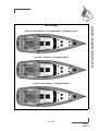
WATER AND SEWAGE WATER
Deck drainage
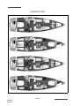
Version 2 aft cabin(s) - 1 Forward cabin - 1 Skipper's cabin
Version 1 aft cabin - 3 Forward cabins
Version 2 aft cabin(s) - 3 Forward cabins
89/166
090282
Index G
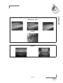
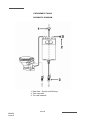
EXECREMENT TANKS
SCHEMATIC DIAGRAM
1. Deck filler - Suction and Rinsing
2. Tank vent hole
3. Thru-hull seacock
90/166
090282
Index G
9
ELECTRICAL EQUIPMENT
GENERAL INFORMATION
12 V DC SYSTEM
24 V DC SYSTEM
110-220 V AC SYSTEM
EQUIPMENT
91/166
090282
Index G
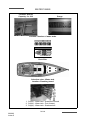
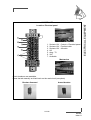
ELECTRICAL EQUIPMENT - 12V
BATTERY SWITCH - 12V
Location: Companionway - Starboard
1. Common negative
2. Service positive
3. Positive engine
BATTERY SET - 12V
Location: Chart table
1. Motor: 60A
2. Service: 50A
BATTERY CHARGERS - 12V 25A
Location: Companionway - Starboard and port
BATTERY CHARGER
Operation
The battery charger operates based on a signal processor that converts alternating current
(220V or 110V) into a direct current (12V). The operation of the charger is fully automatic, after
selecting the type of battery and load type (Refer to the instructions for use).
VOLTMETER - 12V
Location: Electrical panel
GENERAL FUSE 12V SYSTEM
92/166
090282
Index G
12V BREAKER
Location: Electrical panel
1.
2.
3.
4.
5.
6.
7.
Sockets 12V - Cockpit + Electrical panel
Sockets 12V - Forward cabin
Sockets 12V - Aft cabin
Hifi
Amp - TV
VHF
Available
Mechanism
Circuit breakers are resettable.
Press the tab manually on black back on the road circuit (see photo)
Breaker disarmed
Armed breaker
93/166
090282
Index G
ELECTRICAL EQUIPMENT
9
GENERAL INFORMATION
ELECTRICAL PANEL
The electrical switchboard does not require any routine maintenance. In case an electric
appliance is not energized, check:
- The main power supply (batteries, battery switches).
- The switches and circuit breakers on the line.
- the relevant electrical unit.
5
6
7
8
9
10
11
12
13
14
15
16
17
18
19
20
21
22
23
24
25
26
27
4
OFF
3
+
FF
O
V
-
AMP
12V
GAS
24V
AMPS
VOLTS
INT
EXT
2
ON
ON
OFF
1
1
2
1
OFF
1
2
2
AUTO
ON
AUTO
ON
WATER
3
3
1
2
3
4
4
Scheiber
DC - 10A MAX
DC
1. 12V socket
2. "Interior lighting" general circuit-breaker
3. Switch - Backlighting - Panel
4. Control - Forward bilge pump
5. Control - Water unit
6. Control - Fridge - Galley
7. Control - Saloon lighting 1
8. Control - Bilge pump - Saloon - Auxiliary
9. Control - Freezer - Galley
10. Control - Fridge - Chart table
11. Control - Saloon lighting 2
12. Control - Bilge pump - Principal Saloon
13. Control - Pump for deck washing
14. Control - Navigation electronics
15. Control - Solenoid - Gas
16. Control - Navigation lights & Mooring
light
17. Forcing - Steaming light
18. Control - Projector boom bar
19. Control - Deck searchlight
20. Indicator - Voltage
21. Indicator - Water level
22. Master switch - Measurement - Voltage
23. Master switch - Water level measure
24. Master switch - Measurement - Level
Fuel
25. Master switch - Current measurement
26. Display - Current measurement
27. Display - Measurement - Level Fuel
94/166
090282
Index G
ELECTRICAL CIRCUIT, 24 V
- Never work on a live electric fitting.
- The batteries must be strongly fastened.
- Do not block the battery ventilation ducts, some of them may give off hydrogen which
represents a danger of explosion.
- The batteries must be handled with care. In the case of contact with electrolyte
thoroughly rinse off the affected part of the body and consult a doctor.
- To avoid short-circuiting between the battery poles do not store conducting objects near
to the batteries (metal tools, etc...).
- Turn off the electrical circuit with the battery switches when installing batteries or during
their connection/disconnection.
- Never modify the specifications of power overload protection devices.
- Never modify an installation. Use the services of a qualified marine electricity technician.
- Never install or replace the electric appliances (or any electric equipement) by
components exceeding the capacity (amperage) of the circuit.
- Do not leave the vessel unattended when the electrical system is switched on .
- Certain lights represent a significant heat source, be careful of surrounding objects.
Note, the son of the 24 V circuit are white or brown for the blue and more for less.
DANGER
- There may be danger of fire or explosion if direct current systems are
incorrectly used.
WARNING
- Handle the batteries with care (Please refer to the manufacturer's
instructions.
- In case of electrolyte splashing, thoroughly rinse the part of the body that
has been in conctact with it. Obtain medical advice.
ADVICE - RECOMMENDATION
-
Keep the batteries clean and dry in order to avoid premature wear.
Periodically check the electrolyte level. Add distilled water when needed.
Tighten and maintain the terminal connectors by greasing them regularly.
Disconnect the batteries during winter storage or long periods of inactivity.
95/166
090282
Index G
ELECTRICAL EQUIPMENT
9
GENERAL RECOMMENDATIONS
BATTERIES
Battery charging is achieved through the alternator coupled to the engine or through use
of the 220 V shore charger.
Keep the batteries charged enough (essential to ensure them a correct service life).
Make the most of time alongside to use the 220 V shore charger so as to start out sailing
with fully charged batteries.
Always check the condition of the batteries and charge system before putting to sea.
Be sure to always recharge the 24 V battery set after a day's navigation under sail.
Battery set: 24V
Location: Starboard saloon
Service: 4 x 120A
Location: under the kitchen
Spare battery: 4 x 120A
Battery chargers - 2 x 24V 60A
Location: Under map table
Voltmeter - 24V
Location: Electrical panel
General fuse - 24V system
96/166
090282
Index G
9
BATTERY SWITCH
The electricity onboard is 24V DC.
ELECTRICAL EQUIPMENT
The electrical system consists of service batteries.
The batteries supply power to all the functions on board.
Switch on the electricity by turning the positive and negative battery switches.
1. Common negative
2. Positive Service
WARNING
- Never work on a live electric fitting.
- Do not touch battery terminals, risk of electric shock.
PRECAUTION
- Switch off the electrical system with the battery switches when the boat is unattended.
- Never leave the vessel unattended with the mains electricity switched on.
- Turn off the electrical system with the battery switches and circuit breakers before
gaining access to the rear of the electrical panels.
- Check the level of maintainable lead batteries.
ADVICE - RECOMMENDATION
- It is recommended that you switch off all electrical devices before turning off the
battery switches.
97/166
090282
Index G
BOW THRUSTER
LOCATION
FORWARD CABIN
1. Battery set - 4 x 50A
2. Fuse - 250A
3. Electric battery switch - Positive
Bow thruster - 24V
Nozzle
OPERATION
The thruster works with the vessel's engine running.
The bow thruster control is supplied by the 24V service batteries.
Controls in the cockpit
WARNING
Refer to the apparatus instructions for use and maintenance.
98/166
090282
Index G
WINCHES ELECTRIC
9
Spinnaker sheet winches
Access - Relay box: Garage
Circuit breakers
Location: Starboard saloon
Genoa sheet winches - 100A
Spinnaker sheet winches - 60A
Coach roof winches - 60A
Genoa sheet winches
Motor - 24V + Relay box
Access: Deckhead - Cabins
OPERATION
Electrical contactors - in the cockpit
WARNING
Refer to the apparatus instructions for use and maintenance.
Heavy use is made of the batteries when operating the electrical winches.
Be sure to always recharge the 24 V battery set after a day's navigation
under sail.
99/166
090282
Index G
ELECTRICAL EQUIPMENT
LOCATION
FRIDGE
LOCATION
Refrigeration unit - Under the kitchen Exchanger - Under saloon floor Port side
cupboard
Fridge - Cockpit Drainage Fridge - In the sump well
Location: Garage - Starboard
1. Exchanger
2. Refrigeration unit
WARNING
- Refer to the apparatus instructions for use and maintenance.
- Defrost the fridge regularly / Cool boxes.
- During long absence leave the fridge and icebox doors open to avoid
mould developing.
Inverter - 24V / 220V
Location: Starboard saloon
Control box
1. Differential circuit breaker 16A
2. Inverter 1800W
Earthing plate - Galley floor
Fuse - 200A
WARNING
- Defrost the fridge regularly / Cool boxes.
- During long absence leave the fridge and icebox doors open to avoid
mould developing.
100/166
090282
Index G
CIRCUIT BREAKERS 24V
9
LOCATION
"
!
#
!"
1. Saloon lighting
2. Kitchen lighting - Chart table
3. Lighting - Aft locker - Cockpit - Engine
compartment
4. Cabins & Heads version - forward
5. Cabins & Heads version - aft
6. Navigation lights
7. Mooring light
8. Deck searchlight
9. Projector boom bar
ELECTRICAL EQUIPMENT
Back of electrical panel
!
10.
11.
12.
13.
14.
15.
16.
17.
18.
Plus after contact
Windlass
Bow thruster
Navigation instrument
Shower pump - aft
Shower pump - forward
Gangway
Gauge dial - Sewage tank
Available
Mechanism
Circuit breakers are resettable.
Press the tab manually on black back on the road circuit (see photo).
Breaker disarmed
Armed breaker
101/166
090282
Index G
RELAY BOX
Location: Back of electrical panel
24V 10A
24V 25A
1. Lighting - Gangway - Saloon
2. Lighting - Deckhead - Saloon
3. Navigation lights
4. Steaming light
5. Mooring light
6. Deck searchlight
7. Projector boom bar
8. Authorization windlass
9. Authorization Propulsion
10. Electronic
!
"
#
WARNING
Always replace a fuse with one of the same size.
102/166
090282
Index G
9
Electrical cabinet
Motor 24V + Tank
Gangway
Breaker 125A
Location: Port saloon
ELECTRICAL EQUIPMENT
GANGWAY
Location: Garage
Control
Operation
The gateway combines the functions of
gateway and davit.
Maximum load: 150 kg
Open length: 1,875 m
WARNING
- Refer to the manufacturer's instructions for use and maintenance.
103/166
090282
Index G
TELEVISION / HOME CINEMA
Wave inverters 24V / 220V
Location: Electrical panel
TV aerial amplifier
Location: Saloon
Bass speaker
Location: Port saloon
OPERATION
The televisions power, supplied by a transformer which is powered with batteries of service,
operates at 12V.
Starting up: First turn on the circuit breaker, then switch on the TV. The transformer is
switched on and off automatically when you turn on or off the breaker.
ELECTRIC GENOA FURLING SYSTEM
Electronics box
Location: Forward cabin
Breaker 50A
Location: Port saloon
Control
GARAGE
Garage opening - Control
Location: Port cockpit locker
Garage Open
DANGER
It is prohibited to open or leave open the garage while sailing.
Maximum working load: 5 persons or 400 kg.
104/166
090282
Index G
9
Remote control
Relay box
ELECTRICAL EQUIPMENT
WINCH
Location
INFLATOR
Function INFLATOR
Location: Garage
Function DEFLATER
Refer to the apparatus instructions for use and maintenance.
LAUNCHING RAMP
Attachment to open quarterdeck
105/166
090282
Index G
SHORE POWER SOCKET
Socket 220V 50A / 32A
Breaker 220V 63A /32A - Port aft locker
106/166
090282
Index G
ADVICE - RECOMMENDATION
In order to reduce the risks of electic shock and fire:
- Before you plug in or unplug the boat/shore supply cable, switch off the shut off device
connected to the shore supply.
- Plug in the boat/shore supply cable in the boat before you plug it into the shore supply
socket.
- Unplug the boat/shore supply cable on shore first. Close the shore socket cover.
- Do not modify the connections of the boat/shore supply cable.
DANGER
Unplug the dock before leaving the dock.
107/166
090282
Index G
ELECTRICAL EQUIPMENT
9
ELECTRICAL CIRCUIT, 110-220 V
GENERAL RECOMMENDATIONS
Certain vessels are equipped (as either standard or optional features depending on the
model)with a 110 V or 220 V circuit.
The following measures are recommended in order to avoid the danger of electrical shock
and fire:
- Never work on a live electric fitting.
- Plug in the boat/shore supply cable in the boat before you plug it into the shore supply
socket.
- Never let the end of the boat/shore supply cable hang in the water.
- Turn off the shore supply with the onboard cut-off switch before connecting or
disconnecting the vessel/shore supply line.
- Disconnect the ship/shore power cable at the shore socket first.
- Check the polarity indicator for the shore connections.
- If the reverse polarity indicator is activated immediately disconnect the cable. Rectify
the polarity fault before using the vessel's electrical installation.
- Close the shore supply input cover firmly after use (Version/Optional equipment
115V AC).
- Do not modify the vessel/shore supply line connections; only use compatible
connections.
- Do not alter the vessel's electrical system. The installation, modifications and
maintenance must be carried out by a qualified marine electricity technician. Check the
system at least twice a year.
- Disconnect the vessel supply when the system is not being used. This is to prevent the
danger of fire.
- Use double insulated or earthed appliances.
WARNING
- Handle the batteries with care (Please refer to the manufacturer's
instructions).
- In case of electrolyte splashing, thoroughly rinse the part of the body that
has been in conctact with it. Obtain medical advice.
108/166
090282
Index G
9
DANGER
- Never let the end of the boat/shore supply cable hang in the water: The
result may be an electric field liable to hurt or kill the swimmers nearby.
- There may be danger of electrocution if alternating current systems are
incorrectly used.
PRECAUTION
-
Never modify an electric fitting and relevant diagrams yourself.
Call in a technician skilled in marine electricity to carry out any electric modification.
Never change the breaking capacity (amperage) of the overcurrent safety devices.
Never install or replace the electric appliances (or any electric equipement) by
components exceeding the capacity (amperage) of the circuit (Watt for bulbs).
109/166
090282
Index G
ELECTRICAL EQUIPMENT
Note that the live wires are brown, the neutral ones are blue and the earth wires are
green and yellow.
Circuit breakers 220V / Master switch - Shore / Generator
Location: Chart table unit
1
2
3
220V 50Hz
4
15A
15A
15A
15A
15A
15A
5
6
1. Battery charger 24V
2. Battery charger 24V
3. Battery charger 12V
4. Water heater
5. Extractor hood
6. Available
7. Ceramic hob
110/166
090282
Index G
32A
7
9
ELECTRICAL EQUIPMENT
Circuit breakers 220V / Master switch - Shore / Generator
Location: Chart table unit
1
220V 50Hz
2
15A
15A
15A
15A
15A
15A
3
4
15A
5
15A
6
1. Sockets x 3
2. Microwave
3. Dishwasher
4. Washer
5. Ice maker
6. Water maker
111/166
090282
Index G
Circuit breakers 110V
Location: Chart table unit
1
2
110V 60Hz
TEST
TEST
20A
20A
3
15A
15A
20A
4
5
1. Ice maker + Sockets
2. Oven + Dishwasher
3. Socket
4. Washer
5. Water maker
EQUIPMENT
GENERAL INTRODUCTION
(As far as possible) use electric appliances with double insulation or with three conductors
(Neutral-Live wire-Ground).
112/166
090282
Index G
9
ELECTRONIC
Do not install electronic instruments or repeaters less than 1,50 m away from the radio
loudspeakers.
Advice: For further information refer to the appliance instructions.
LEAD LINES
The log and depth sounder sensors are located under the forward cabin floor. Keep the log
sensor cowl close to the instrument so as to be able to intervene in complete safety.
Do not store material on top of the sensors.
AUTO PILOT
The pilot consists of several elements listed as follows:
- Repeater in the cockpit.
- Compass in the aft starboard cabin closet. A pictogram helps to locate it easily.
- Valve, hydraulic pump, rudder blade on either side of the bar sector in the rear locker
(acces via one of the two cockpit lockers aft cabin port).
- To supply power to all elements switch on the "Navigation" circuit breaker on the
electrical panel.
- For use and maintenance of the material consult the manufacturer instructions.
MAINTENANCE
Clean the transducer probe during each dry dock and the log sensor regularly. Read the
instructions for maintenance recommendations.
Refer to chapter 12 "Launching" for the precautions to be taken concerning the sensors
during hoisting.
ADVICE - RECOMMENDATION
- For best results, remove any metal compass..
- Do not store material close to the calculator and electrical connections.
113/166
090282
Index G
ELECTRICAL EQUIPMENT
Wire runs are available to complete the boat equipment.
MAINTENANCE
Clean the repeater dials with freshwater. Refer to the instructions before using any other
produce. The use of alcohol must be avoided.
ADVICE - RECOMMENDATION
-
Place the protective covers on the repeaters when unused for long periods.
When sailing store the protective covers inside the boat to avoid losing them.
The various repeater displays are back-lit.
The onboard radio is fitted with two outside speakers.
When mooring be careful to adjust the sound so as not to disturb your neighbours.
TRANSDUCER LOCATION
114/166
090282
Index G
AUTO PILOT
Layout of components
Auto pilot (Reference 1)
Gyrocompass (Reference 2)
Vessel Management Unit (Reference 3)
115/166
090282
Index G
ELECTRICAL EQUIPMENT
9
GENERATOR
Electrical earthing
Location: Galley floor
Tank - Cooling liquid
+ 220V breaker (Reference 4)
Drainage - Sea water (Reference 1)
WARNING
- Refer to the manufacturer's manual given with your boat.
116/166
090282
Index G
9
ELECTRICAL EQUIPMENT
GENERATOR SYNOPTIC
REF
1
2
3
4
5
6
7
8
9
10
Designation
Fuel filter
Sea water filter
Water trap
Anti-siphon valve
Differential circuit breaker
Generator
Water - Gas separator
Seawater inlet
Drainage - Sea water
Outlet
117/166
090282
Index G
Water - Gas separator (Reference 2)
Quilting on reservoir (Reference 5)
Seawater inlet (Reference 3)
Remote control (Reference 6)
Battery (Reference 7)
Generator + + Diesel filter
Battery switch (Reference 8)
Anti-siphon valve (Reference 9)
118/166
090282
Index G
GENERATOR - SCHEMA
A generator is a device that can produce electricity (220V or 110V) from a mechanical
energy (fuel). The generator will fed the onboard equipment operating at 220V or 110V,
moored or sailing.
OPERATION:
- Open the raw water intake valves and evacuation valves.
- Turn the generator's battery switch to the ON position.
- Switch the generator breaker (referencie 5) ON.
- Turn the generator on by remote control (located on the nautical chart table) or your at
your own generator.
- Check that any device is not running 220V or 110V. Then set the shore power/
generator switch (located on the chart table).
OPERATION:
- Supply - Diesel:
The generator is fed by fuel through the fuel tank port. The fuel filter (reference 1) is located
at the generator circuit.
- Refrigeration:
The generator is cooled:
by seawater (inlet valve reference 8 sea water and sea water filter reference 2) ;
and by air (air exhaust duct, thats runs through a ventilator and through the fresh air inlet).
- Electricity:
The generator includes its own battery to start the engine. The generator is earthed by an
earthing plate which is located under the hull.
- Rejection:
The cooling water and exhaust gases are separated in the separator (reference 7) to avoid
noise pollution.
The seawater is discharged below the waterline (Ref 9). The exhaust- pipe is located
above the waterline (Ref 10).
119/166
090282
Index G
ELECTRICAL EQUIPMENT
9
GENERAL POINTS:
AIR CONDITIONING
GENERAL POINTS:
The air-conditioning cools the air temperature inside the boat (only when the boat is floating
in water).
The cooling circuit consists of one or more compressors that operate independently. A
compressor is called "reversible" because it can heat the boat if the sea water temperature
exceeds 10°C.
In winter, you can programme the dehumidifier function on the airconditioning controls.
The refrigeration compressors are made by one or two seawater pumps. These pumps are
powered by 220V or 110V and are guided by one or two relay boxes.
Sea water is evacuated through a through-hull fitting equipped with a valve, located above
the waterline.
Each compressor has its own through-hull evacuation fitting. It is advisable to check the
flow of water visually once the air conditioning starts running.
OPERATION:
Before starting the engine:
- Open the raw water intake valves and evacuation valves.
- Use the switch on the chart table to select the power source (shore power or
generator).
If using shore power: plug into the shore power socket ;
If using the generator: before turning on the air conditioning, leave the generator running
for about 3 minutes.
The air conditioning is running:
- Switch the circuit breakers 220V ,from the air conditioning,ON.
- Select the temperature of each compressor using the control units.
120/166
090282
Index G
WINTER STORAGE:
9
Protection of sea water system: drain the whole sea water system.
This glycol present in the water protects the pipes against freezing to a temperature of
about -7° C. If the boat is sailed or wintered below the lowest temperatures, it is necessary
to increase this proportion of glycol to a level of 40%. The air conditioning must never be
operated with this mixture containing a greater proportion of glycol.
When wintering, before bringing the air conditioning system back into operation in milder
temperatures, it is essential to bring the proportion of glycol back to a level of 15% to use
the air conditioning.
Note: These two maintenance operations (wintering/unwintering) owing to negative temperatures
must be carried out by a professional.
WARNING
-
Refer to the apparatus instructions for use and maintenance.
Never start the generator when the climate function is already on.
Always turn off the air conditioning before turning off the generator.
Regularly check and clean the sea water filter placed on the sea water
intake through-hull fitting.
- Clean the air filter (located in the compressor) regularly for maximum
performance of the installation.
121/166
090282
Index G
ELECTRICAL EQUIPMENT
Protection of the chilled water system: The chilled water in the air conditioning
piping is made up of a mixture of water and glycol at a level of 15%.
Box - Circuit breakers (Reference 4)
1
2
D1
D2
2A
3
1.
2.
3.
4.
5.
6.
7.
8.
220V 50Hz
2A
D4
D5
D6
D7
D8
D9
10A
10A
10A
10A
10A
10A
4
5
6
Pump - Port saloon
Pump - Starboard saloon
Compressor - Port saloon
Compressor - Starboard saloon
Compressor - Port forward cabin
Compressor - Starboard aft cabin (owner or rear)
Compressor - Port forward cabin
Compressor - Starboard forward cabin (or prior owner)
122/166
090282
Index G
7
8
OPERATION
Electricity: The heater circuit is powered by 12V thanks to the battery backup.
9
Diesel: Quilting on reservoir.
STARTING UP
ELECTRICAL EQUIPMENT
- Verify that the circuit * 1V is turned on.
- Open the heater outlet.
- Turn the control box at ON.
- Adjust the temperature of the heater using the thermostat.
HEATING
Layout of components
Heater
(Reference 1)
Diesel pump + Supply valve (Reference 2)
Control (Reference 3)
123/166
090282
Index G
LOCATION - COMPRESSORS
Pump - Seawater inlet (Reference 1 and 6)
Maintenance of filters (to engage in regular):
- Close valves taken seawater.
- Unscrew the top of the filter.
- Clean the strainer.
- Put everything back in place.
Drainage - Sea water
Forward port cabin and port saloon
compressor (Reference 2)
Drainage - Sea water
Compressor - Aft cabin
(Reference 3)
Pump relays - Sea water
(Reference 5)
Drainage - Sea water
Starboard saloon and forward starboard
cabin compressor (Reference 7)
Control
124/166
090282
Index G
WASHER
Layout of components
Filter
(Reference 1)
220V socket + Supply valve House water (Reference 2)
Washer (Reference 3)
Drainage (Reference 4)
125/166
090282
Index G
ELECTRICAL EQUIPMENT
9
DISHWASHER
Layout of components
Dishwasher (Reference 1)
220V socket (Reference 2)
Supply valve - House water (Reference 3)
Drainage - System - Sink (Reference 4)
126/166
090282
Index G
9
EXTRACTOR HOOD
127/166
090282
Index G
10
ENGINE
GENERAL INFORMATION
ENGINE FITTING
129/166
090282
Index G
*
Diesel tank
Capacity: 420 l
Location: Aft cabin
Diesel tank additional (Replace the water reservoir)
Capacity: 310 l
Location: Port saloon
Supply valve - Detail
1.
2.
3.
4.
5.
Heater - Port side
Heater - Starboard
Generator
Motor
Diesel transfer
Deck filler
Gauge
Location: Electrical panel
Position / Name of fuel tanks
FUEL TANK
130/166
090282
Index G
GENERAL INFORMATION
10
TYPE OF MOTORISATION
The transmission is of a shaftline type.
PRECAUTIONS OF USE, OPERATING ADVICE
General point
- In this vessel, do not install an engine with a greater power and weight than that
recommended, this will create a danger for its stability.
- Fuel which is stored elsewhere than in the fuel-tanks (portable tanks, jerrycans, etc...)
must be kept in a ventilated space.
- Make sure that the engine compartment is clean and dry.
- Avoid contact between inflammable substances and the hot parts of the engine.
- Locate the extinguisher hole which allows access to the engine compartment if a fire
should break out. (Refer to chapter 2).
Filling
Take the general precautions stated in chapter 8 about the water tank filling.
Fill the fuel tank using the filler. In order to protect the deck from possible fuel splash, wet
the area around the filler with sea water before you remove the filler cap. In case of
splashing rinse the deck thoroughly (deck filler closed).
The fuel level is transmitted from the dipstick to the guage located on the house electrical
panel.
DANGER
- Stop the engine and refrain from smoking during fuel tank filling.
- Make sure that the ventilation openings in the engine (and generator, if
installed) compartment are well cleared.
PRECAUTION
- Never run the engine when the boat is hauled out.
ADVICE - RECOMMENDATION
- Carefully read the engine instructions given with your boat.
131/166
090282
Index G
ENGINE
Your vessel is fitted with an in-board diesel engine.
WARNING
- The tanks' nominal capacity cannot be fully used due to the load and the
need to maintain the correct trim. A 20% reserve should be kept.
PRECAUTION
- Stop the engine before you open the companionway hatch and side hatches.
In case of an intervention when the engine is running:
- Stay away from belts and hot or mobile parts.
- Be careful with full clothes, long hair, rings etc. (you may be caught).
- Wear appropriate clothes (gloves, caps etc.).
132/166
090282
Index G
ENGINE FITTING
ENGINE
10
1.
2.
3.
4.
5.
6.
7.
Anti-siphon valve (Cupboard - Starboard aft cabin)
Stern frame join
Propeller shaft
Flange
Sea water filter
Filter - Diesel
Engine compartment ventilator
133/166
090282
Index G
Engine supply valves / Access (Reference 2)
Valve - Sea water inlet valve for engine (Reference 1)
Motor
These instructions give detailed explanations on proper operation of the engine.
- Refill before the fuel tanks have almost run dry (the fuel system may be stopped for
lack of fuel).
- Make sure you have enough fuel before sailing.
134/166
090282
Index G
Access to the engine
10
Access to the engine is via the companionway and the saloon and the aft cabins.
You can check the main parts via side and aft hatches.
The water inlet valve of the engine is essential in the engine operation.
- Keep the strainer under the hull as clean as possible.
- Brush the strainer whenever the boat is lifted out.
- Do not cover the strainer with antifouling paint.
It is essential that this valve is open before the engine is started (danger of rapid wear and
substantial damage to engine installation).
If water does not flow out:
- Stop the engine immediately.
- Check that the valve is open.
Close the water inlet valve if the boat is unattended for long.
Inspect and clean the water filter regularly.
Engine operation
Before starting the engine:
- Turn on the fuel valve.
- Open the valve of the engine cooling system and the valve of the stuffing box (see
stuffing box paragraph).
- Operate the battery switches and energise the electric system.
- Disengage the reverse gear (it will make the acceleration possible when in neutral).
DANGER
- Always start the engine with the control lever in neutral.
ADVICE - RECOMMENDATION
- Get used to checking immediately after starting the engine if water is expelled with the
exhaust gases.
WARNING
- Never switch off or de-energise the electric system when the engine is
running.
- Imperatively operate the stop pull handle (or button) before using the
ignition key to switch off a diesel engine.
135/166
090282
Index G
ENGINE
Engine water intake valve
10
Fuel filter
The water results either from the condensation resulting from an insufficiently filled tank, or
from a filler cap either not closed properly or with a damaged seal.
In order to prevent any water infiltration, the fuel runs through two filters:
- One filter is an integral part of the engine, its role is to filter fuel very finely. To know
when you have to intervene and how frequently you have to change it, please refer to
the engine's manual.
- The second filter is on the pipe that links the tank to the engine, it plays the role of a
water decanter and prefilter.
Drain by undoing the knurled screw at the base of the decantation bowl(but not removing
it).
Allow to flow into a box till the fuel looks clean.
Do this several times a year.
Change the pre-filter at least once a year (access to it when you remove the bowl).
As for the procedures in case of fire, refer to Chapter 2.
Stuffing box
You have access to the stuffing box through the central technical compartment behind the
engine.
Lubricate the seal every 200 running hours (or at least once a year).
Apply the grease the manufacturer recommends in his instructions.
After launching the boat, drive the air out from the sleeve pinching it with your fingers.
DANGER
- Never obstruct access to the fuel valve.
137/166
090282
Index G
ENGINE
Engine running problems may have different origins, including dirty fuel. The
injection pump may wear out if there is water in the system.
Engine panel detail
(Reference 2)
Handle Engine control
(Reference 1)
Engine ignition kill drawing
1. Anode
2. Propeller
3. P bracket
4. Propeller shaft
5. Stuffing box
6. Connecting device
The instrument panel has all the testing functions of the engine and it does not require any
special precaution (refer to engine leaflet).
Check the clutch and accelerator cables (lubricate the end fittings and forks).
138/166
090282
Index G
The international regulations to prevent collision at sea (COLREG) and the course
regulations make mandatory a permanent and proper surveillance and the respect of
priority.
Make sure there is no other boat on your way.
The visibility from the steering station may be obstructed in the following conditions:
- Speed.
- Position of the upper and side awnings.
- Boat heeling over, the sails reduce visibility under wind.
- Load and load distribution.
- Sea conditions, rain, spray, fog or darkness.
- Lights on inside the boat.
- Persons and removable equipment in the helmsman's field of visibility.
ADVICE - RECOMMENDATION
- When the engine is running, avoid making noise and chops near the other users.
- Respect speed limits.
- If this boat is equipped with a fixed blade propeller, when sailing at speeds over 8
knots it is essential to leave the reverse gear control in neutral.
- To start the engine again, reduce the speed of the boat when sailing (in order to be
able to disengage the clutch before starting it again).
PRECAUTION
- Do not change the propeller without specialist's advice.
- Regularly check the anode (at the end of the drive shaft) for corrosion, at least 2 times
a year.
ADVICE - RECOMMENDATION
- Change the anode if necessary (Before it lost 50% of its weight).
- Use anodes corresponding to the zone of navigation of the boat (fresh water / sea
water).
- If bases are raised, anodes are outside the water: respect the recommendations of the
motoriste.
WARNING
- Change systematically anodes at the end of the first 3 or 4 months of
launch of the new boat: their wear is accelerated during this period.
139/166
090282
Index G
ENGINE
10
VISIBILITY FROM THE STEERING STATION
NAVIGATION: REMINDER OF SOME ADVICE
Stability
During sailing keep all the portholes, windows and doors closed.
- The stability is reduced when you add weight in the upper parts.
- Stability may be reduced when towing a boat or when heavy weights are lifted with the
davits.
- Breaking waves represent a serious danger for stability and for taking in water. Close
the companionway doors and hatches in heavy seas.
Prevention of man overboard
Regularly check the guard-rails:
- With metal guard-rails, watch for corrosion particularly at connecting points.
- With synthetic guard-rails, change them as soon as they show signs of wear due to
chafing or UV.
Propeller
The propeller supplied as a standard with you boat is the result of tests carried out jointly
with the engine manufacturer.
ADVICE - RECOMMENDATION
- Check the whole propeller shaft several times a year.
- Check and change the cutlass bearing if necessary.
- Have the whole driving and steering systems checked and maintained by a
professional.
- Refer to the manufacturers' instructions supplied with your boat.
- Regularly check the O ring of the filler for good condition (in order to prevent water
entries).
- Do not turn off the fuel tap after each use (except in case the boat is unattended for
long).
- Keep the fuel tank as full as possible (to avoid condensation).
- Every year check the fuel system for condition (hose, valves, etc.).
- Have a professional to carry out the works on the damaged parts of the fuel system.
- Refer to the manufacturer's manual given with your boat.
- Be careful with any possible risk of oil and fuel spillage.
140/166
090282
Index G
360 DOCKING VERSION
10
General points
- This type of transmission operates without a reverse gear, reversing is achieved by
rotating the POD 180 degrees.
- The "360 Docking" system is supplied by the boat's services circuit: the battery bank
must be sufficiently charged to enable the system to run well. An insufficiently charged
battery bank (at the start of a new season, for example) risks damaging the onboard
electrical system.
- The forward and reverse travel of the boat are controlled by the engine control lever.
In passing from forward into reverse POD rotates 180°.
- The POD's orientation in all directions is carried out by the joystick.
- The joystick controls the propeller and the bow-thruster. By moving the joystick on
the X and Y axes, the boat moves on these axes.
- Rotating the joystick makes the boat rotate around its centre.
ADVICE - RECOMMENDATION
- It is imperative to change the transmission oil after the 25 first hours of use (please
consult your dealer).
141/166
090282
Index G
ENGINE
- The 360 Docking transmission is an electronically controlled mechanical transmission.
Start Quick Guide
Start the engine using the control lever (forward and reverse)
1
Turn on all battery switches.
2
Start the engine.
3
(if necessary) Activate the bow thruster manually: Steady green light on
the control panel.
4
The lever is operational.
Start the engine, using the joystick to move sideways (360 Docking)
1
Turn on all battery switches.
2
Turn on power to the navigation electronics at the electrical panel.
3
If necessary according to auto pilot model, put into STAND-BY mode at
the exterior helm station.
4
Start the engine.
5
Activate the bow thruster manually: Steady green light on the control
panel.
6
Activate the joystick of the 360 Docking by pressing the joystick button
(Hold the button down for a long time and the 2 indicator lights will
changed to steady green).
7
The joystick is operational.
Deactivate the joystick to take control of the engine with the lever
1
Hold the joystick button down for a long time (1 red indicator light).
2
The engine control lever is operational.
142/166
090282
Index G
Diagrammatic view
ENGINE
10
Reference
Designation
1
Heat engine
POD rotary motor: Make the POD under the waterline turn 270 to
starboard
Clutch actuator: enables gear engagement and disengagement
Clutch: Mechanical linkage between the engine and the propeller shaft
TCU: (Transmission and Clutch Management) interface between the
clutch activator and the VMU
VMU (Vessel Management Unit): the brains of the system, it gathers all
the info from the system(joystick, control lever, TCU, POD..) and tells it
what to do
Throttle actuator: electric accelerator interface between the electric
control and the fuel pump
2
3
4
5
6
7
143/166
090282
Index G
LAYOUT OF COMPONENTS
Rotating motor
(Ref 2)
Clutch actuator
(Ref 3)
TCU housing
(Transmission and Clutch Management)
(Ref 5)
VMU housing
(Vessel Management Unit)
(Ref 6)
Throttle actuator
(Ref 7)
144/166
090282
Index G
X3
Bow Thruster (no ZF)
C
X3
X2
X2
X5
RPM sensor
X6
B
X4
Autopilot (no ZF)
Power
X3
RPM sensor adapter
Throttle acuator
Angular steering sensor
Main Harness VMU
A
A
B
Throttle cable
X10 (only ZF)
X9
Joystick
X6 - CAN In
145/166
V.M.U.
CAN
Harness
Termination
resistor
Side Mounting
Control head
Control head harness
LAYOUT
X8
X1
Steering electrical
motor harness
safety connector
X6 normal
Clutch actuator
Throttle cable
or
X8 (K-line only ZF)
Throttle cable
X4
X6 - CAN In
Consolle Mounting Control head
X7 - CAN Out
X3
X5
T.C.U. Harness
Termination
resistor
Power
Filter box
Power
X7 - CAN Out
Power
T.C.U.
Steering motor
10
090282
Index G
ENGINE
Operation
1. General points
- The 360 Docking system is a manoeuvring aid to facilitate coming alongside and
leaving the dock. This system must not in any circumstances be used as a means of
navigation, even during approach manoeuvres in port.
- In some use modes of the system, especially sideways movement, the bow thruster
has to work very hard. This leads to a significant power draw on the bow thruster
battery bank and raises the temperature of the bow thruster motor.
- For its protection, the bow thruster is equipped with a temperature alarm which gives
5 short beeps 10 seconds before cutting off the power to the bow thruster. When the
bow thruster cuts out, keep your hand on the joystick with the bow thruster out of
operation. You need to wait until it has cooled sufficiently before restarting it manually
by pressing both buttons on the bow thruster control simultaneously.
- To avoid this inconvenience and to protect the bow thruster we advise you not to use
the bow thruster for more than 30 seconds at a time and to allow it to cool between
each use.
Note: Once the bow thruster has cut out due to overheating you should allow around
4 hours for it to return to ambient temperature. If it does overheat you can start using
it again without waiting 4 hours but the possible usage time will be reduced.
- After each manoeuvre using the bow thruster, be sure to maintain the charge of the
bow thruster battery bank: either by connecting your boat to the mains socket on the
dock, or by keeping the engine at a cruising speed of at least 1700 rpm (engaged or
disengaged) for at least 30 minutes after the last manoeuvre.
2. Propeller
WARNING
The propeller supplied with the boat is the only propeller validated by the
engine manufacturer that allows optimal operation of the 360 Docking
assembly. No other propeller should be fitted otherwise there will be
serious malfunction of the base or of the engine itself.
146/166
090282
Index G
3. Operation
10
- Turn on all battery switches. The bow thruster battery master switches will turn
on automatically when the bow thruster control is picked up.
- Open the engine water inlet valve.
- Switch on the navigation electronics (Electrical panel).
- According to the auto pilot model and screen model, it may be necessary to touch the
POWER button on the screen at the helm station to activate the auto pilot in
"MOTORISED HELM" mode or POWER
- Check that the engine control lever is in neutral.
- Switch on the engine.
- Start the engine.
- Activate the bow thruster manually using the control push button. A steady light
illuminates on the bow thruster control panel: The system is operating.
- Press the joystick button and hold down for 2 seconds before activating the joystick
(When the button is released, the 2 LEDs on the joystick will change to steady green).
4. Joystick operation
- REMINDER: Before using the system, ensure that the bow thruster light is illuminated
(see above) once the boat's engine is startedCheck that the bow thruster indicator light
is showing steady green when the joystick is in operation.
DANGER
If you activate the joystick while the rudder blade is not in the same position
as the boat's axis, it will automatically move itself to the correct position.
WARNING
The wheel will spin quickly and may catch your arm, clothes, hands as it
does so: keep away from the wheel when the system is running.
147/166
090282
Index G
ENGINE
- Open the fuel supply valve(s) from the fuel tank(s).
The joystick is on STAND-BY: This means that it is ready for use.
The «Ready» LED is a steady red. The engine is controlled by the
engine control lever.
Place a hand on the joystick and press the button for 1 second. The
green LEDs illuminate when the button is released.
The 2 LEDs are illuminated as steady green lights (not flashing).
The joystick is operational, the control lever is out of action.
The wheel turns to lock the helm and rudder along the longitudinal
axis of the boat.
Be careful to keep arms clear of wheel as it turns.
The pilot display shows =
"MOTORISED HELM" version RAYMARINE.
POWER version SIMRAD.
The indicator light on the bow thruster control panel is showing
steady green.
Whenever an instruction is given to the joystick (here in forward) the
LED «control» illuminates red.
ADVICE - RECOMMENDATION
- The joystick button must be released to operate the joystick.
148/166
090282
Index G
10
Push the joystick forwards.
The boat moves forwards. The acceleration is proportional to the
position of the joystick.
Push the joystick back.
The boat moves backwards. The acceleration is proportional to the
position of the joystick.
Push the joystick to port.
The boat moves to port. Acceleration can be altered by turning the
joystick (clockwise: boat accelerates, anti-clockwise: boat
decelerates) and the bow thruster operates.
Push the joystick to starboard.
The boat moves to starboard. Acceleration can be altered by turning
the joystick (clockwise: boat accelerates, anti-clockwise: boat
decelerates) and the bow thruster operates.
149/166
090282
Index G
ENGINE
USING THE JOYSTICK
Several movements can be combined
Push the joystick to starboard + Turn the joystick clockwise.
The boat moves to starboard but the bow swings more quickly than the stern.
Push the joystick to starboard + Turn the joystick anti-clockwise.
The boat moves to starboard but the stern swings more quickly than the bow.
You can do the same to port:
Push the joystick to port + Turn the joystick anti-clockwise.
The boat moves to port but the bow swings more quickly than the stern.
Push the joystick to port + Turn the joystick clockwise.
The boat moves to port but the stern swings more quickly than the bow.
WARNING
The effects of the 360 Docking system's rotation will be noticeable to a
greater or lesser extent depending on the boat's way.
150/166
090282
Index G
Turn the joystick anti-clockwise.
The boat turns to port (virtually pivoting around its keel). Forward or
reverse acceleration is proportional to the position of the joystick.
Turn the joystick clockwise.
The boat turns to starboard (virtually pivoting around its keel).
Forward or reverse acceleration is proportional to the position of the
joystick.
Push the joystick forwards + turn clockwise.
The boat moves forward and turns to starboard.
The acceleration is proportional to the position of the joystick.
Do the same manoeuvre turning anti-clockwise.
The boat moves forwards and turns to port.
.The acceleration is proportional to the position of the joystick.
Push the joystick back + turn clockwise
The boat moves backwards and turns to port.
The acceleration is proportional to the position of the joystick.
Do the same manoeuvre turning anti-clockwise.
The boat moves backwards and turns to starboard.
The acceleration is proportional to the position of the joystick.
151/166
090282
Index G
ENGINE
10
QUIT JOYSTICK MODE
Press the button for 1 second.
RAYMARINE version: The auto pilot comes out of "MOTORISED
HELM" mode and goes into STAND-BY mode.
SIMRAD version: The auto pilot comes out of POWER mode and
goes into STAND-BY mode.
The joystick goes into standby.
The «Ready» LED is a steady red.
The system switches automatically to control lever function.
If the lever is not in the neutral position it must be put into neutral
before using.
Explanatory note regarding the joystick in flashing red «Ready» LED mode:
When the red «Ready» LED is flashing, this indicates that a malfunction has been detected
in the system. This malfunction may occur when the engine is started or the joystick is
used.
In some cases, this fault may be resolved by completely restarting the system
(Recommence starting procedure set out above).
If after restarting the joystick is still not working, use the engine control lever and bow
thruster manually.
If control lever is not working, apply emergency procedure SAFETY set out in owner's
manual ZF.
WARNING
To retake control with the engine control lever, it is essential to disengage the
joystick by pressing the button behind the joystick.
152/166
090282
Index G
5. MODE WARM UP (warming up the engine)
10
WARM UP mode is a mode in which the engine is disengaged and accelerated.
ENGINE
To engage the "WARM UP" position, press the button and keep it pressed whilst
moving the throttle to the first forward notch, then release the button. "WARM UP" is only
possible in forward gear.
To come out of WARM UP mode, return the lever to neutral.
6. Procedure for shutting down the engine:
Put the control lever in neutral AFTER ENGAGING FORWARD GEAR FOR A FEW
SECONDS, so the POD is properly located in the ahead position.
Wait 10 seconds before switching off the engine.
153/166
090282
Index G
7. Maintenance
Check engine oil level.
The level must be between the 2 marks on the gauge (see
engine manual).
Check POD base oil level.
The level must be taken by inserting the dipstick in the hole
(without screwing it down).
The level must be between the 2 marks on the gauge (see ZF
manual).
OK
- After every 250-hours of use, or once a year depending on the level of use, the boat
must be lifted out to change the POD oil.
- During cranage: it is imperative to engage forward gear for several seconds to position
the engine base of the boat correctly under the crane before stopping the boat's engine
(see the chapter Handling).
- Every 7 years, replace the POD's packing.
154/166
090282
Index G
10
8. 360 Docking circuit protection
Reference
1
2
3
4
5
6
7
8
7
8
ENGINE
6
3A
3A
5
3A
4
3A
3
20A
2
3A
3A
1
7.5A
Lighted safety fuses
Designation
Supply VHS 1 after engine contact
Supply VHS 2 after engine contact
VMU power supply VMU
VMU power supply TCU 1
VMU power supply TCU 2
Supply VMU after engine contact
Supply TCU after engine contact
Supply pod after engine contact
Motor supply 40A
NOTE: If a safety fuse illuminates, this
means that it is faulty. In this case the
safety fuse must be replaced with a
safety fuse of the same rating (see colour
codes below).
155/166
090282
Index G
11
LAUNCHING
LAUNCHING RECOMMENDATIONS
STEPPING THE MAST
157/166
090282
Index G
POSITIONING DIAGRAM FOR HOISTING CRADLE AND STRAPS
Note: Measurements are expressed in mm.
158/166
090282
Index G
LAUNCHING RECOMMENDATIONS
11
In order to remain completely under guarantee in the case of any failure of parts or
materials the first launching and the first trials of different equipment must be carried out
by your JEANNEAU dealer.
If later you have to launch your boat yourself, you should take the following precautions:
BEFORE LAUNCHING
- If your boat is to be fitted with sounder and speedometer, allow for the relevant fittings
and their installation.
- Check the water intake strain box for cleanliness.
- Check the engine and reduction gear oil levels (refer to engine manual).
- Turn off the engine cooling water drain valves.
- Retract the speedometer into its housing (it may be damaged by the handling belts).
- For the on-line engines, check the anode at the end of the shaft is in place. Check the
nut tightening (the lock washer shall be turned over onto the nut). The anode shall not
be painted.
- Turn off all the water inlet and drain valves (sink, washbasin, heads, engine).
HANDLING
- Install a fore rope, a rear rope and fenders.
- When craning, check that no device is crushed by the belts (sounder, speedometer,
shaft, etc.).
- Locate the strap positions using the stick-on markers. The belt position will be useful
during the craning for a future launching.
WARNING
- Do not stay on board or under the boat during hoisting.
ADVICE - RECOMMENDATION
- The proper working of all your boat's equipment is the result of the quality of the
commissioning operations.
159/166
090282
Index G
LAUNCHING
A lot of skill and care is required to commission your JEANNEAU boat. The proper
working of all your boat's equipment is the result of the quality of the commissioning
operations.
AFTER LAUNCHING
- Check the sounder and speedometer fittings for tightness if need be.
- Open the valves and make sure that they are tight with the hull and relevant hose.
- Check the stuffing box for watertightness (Refer to chapter 11 "Stuffing box").
Before starting the engine, refer to chapter 11 "Motor".
STEPPING THE MAST
Please contact your dealer.
160/166
090282
Index G
12
WINTER STORAGE
LAYING UP
PROTECTION AND MAINTENANCE
161/166
090282
Index G
LAYING UP
- Take ashore all the ship's log, the ropes that are not used for mooring, the galley
equipment, supplies, clothes, the safety equipment, batteries, the gas cylinder.
- Mark again the safety equipment, check the expiration dates, have the liferaft
overhauled.
- Take advantage of this laying up to draw up a complete inventory of the equipment.
PROTECTION AND MAINTENANCE
INTERIOR
- Drain all the fresh water pipes and rinse them with water and vinegar (do not use a
chlorine based product).
- Lubricate and close all the water inlet valves and thru-hull fittings. Rinse and
completely drain the heads bowls and pumps.
- Remove the depth sounder and log sensors.
- Installed in the square of a dehumidifier air leaving the cabin doors and open storage
(cupboards, coolers).
- Leave the cushions outside for long before putting them back into the boat in the
upright and side position in order to have minimum contact surfaces.
EXTERIOR
- Thoroughly rinse the hull and deck.
- Grease all moving and mechanical parts (latches, hinges, locks, etc).
- Protect all ropes and mooring lines against chafing.
- Protect the boat as well as possible with fenders.
- Make sure the boat is properly moored.
This is not an exhaustive list of recommendations. .
ADVICE - RECOMMENDATION
- You alone know all the particularities of your boat and its equipment:
- To lay up your vessel carefully and methodically is the best guarantee to avoid
problems when re-fitting out.
- This is not an exhaustive list of recommendations. Your dealer will give you the advice
you need and will carry out the technical maintenance of your boat.
- Take advantage of this laying up to draw up a complete inventory of the equipment.
162/166
090282
Index G
12
MOTOR
Here are a few major tasks to carry out:
Afloat
- Drain the cooling system and fill it with antifreeze.
- Shut off the battery switches, grease the terminals and check the battery voltage.
- Fill the fuel tanks to a maximum in order to avoid condensation.
- Please refe to the engine manual for anything relating to the engine.
Ashore
- Take the batteries ashore and keep them on maintenance charge.
- Change the anode.
- Carry out the winterization operations specified by the manufacturer, keeping in mind
that the freeze hazard is more significant when the boat is ashore.
- Slacken the a.c. generator and pump belts.
163/166
090282
Index G
WINTER STORAGE
The engine winterization shall be carried out by a professional. Depending on the boat
location, afloat or ashore, winterization is different.
JEANNEAU (Establishment of the company SPBI)
BP 529 - 85505 LES HERBIERS cedex - FRANCE
Tel. (33) 02 51 64 20 20 - Fax (33) 02 51 67 37 65
Internet : http://www.jeanneau.com(fr).
165/166
The present document is not contractual and since we constantly desire to improve our models, we reserve the right to modify them without notice.
JEANNEAU recommends
.
Personal notes