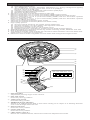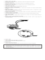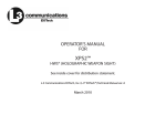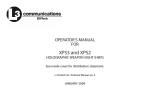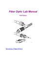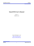
1
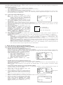
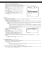
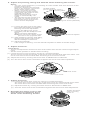
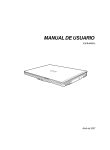
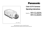
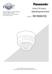
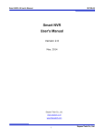
Color CCTV Cameras
Operating Instructions
Model No.
WV-CW474F
WV-CW474S
Before attempting to connect or operate this product,
please read these instructions carefully and save this manual for future use.
N1101-1121
V8QA5931BN
Printed in Japan
N 19
For U.S.A
CAUTION
RISK OF ELECTRIC
SHOCK DO NOT OPEN
CAUTION: TO REDUCE THE RISK OF ELECTRIC SHOCK,
DO NOT REMOVE COVER (OR BACK).
NO USER-SERVICEABLE PARTS INSIDE. REFER SERVICING TO QUALIFIED SERVICE PERSONNEL.
SA 1965
SA 1966
The lightning flash with arrowhead symbol, within an equilateral triangle, is intended to
alert the user to the presence
of uninsulated "dangerous voltage" within the product's enclosure that may be of sufficient
magnitude to constitute a risk
of electric shock to persons.
The exclamation point within
an equilateral triangle is intended to alert the user to the presence of important operating
and maintenance (servicing)
instructions in the literature
accompanying the appliance.
NOTE: This equipment has been tested and
found to comply with the limits for a Class A
digital device, pursuant to Part 15 of the FCC
Rules. These limits are designed to provide
reasonable protection against harmful interference when the equipment is operated in a
commercial environment. This equipment generates, uses, and can radiate radio frequency
energy and, if not installed and used in accordance with the instruction manual, may cause
harmful interference to radio communications.
Operation of this equipment in a residential
area is likely to cause harmful interference in
which case the user will be required to correct
the interference at his own expense.
FCC Caution: To assure continued compliance, (example - use only shielded interface
cables when connecting to computer or
peripheral devices). Any changes or modifications not expressly approved by the party
responsible for compliance could void the
user’s authority to operate this equipment.
The serial number of this product may be found
on the top of the unit.
You should note the serial number of this unit
in the space provided and retain this instruction
as a permanent record of your purchase to aid
identification in the event of theft.
Model No.
Serial No.
WARNING:
To reduce the risk of fire or electric shock, do not expose this appliance to rain or moisture.
PREFACE
Panasonic's WV-CW474F/CW474S series color digital camera introduces a new level of high
picture quality and high resolution through the use of a 1/3-inch interline transfer CCD image
sensor having 768 horizontal pixels (picture elements), and digital signal processing LSIs.
This model offers cutting-edge technology for advanced video surveillance.
PRECAUTIONS
1. Do not attempt to disassemble the camera.
To prevent electric shock, do not remove screws or covers.
There are no user-serviceable parts inside. Ask qualified service personnel for servicing.
2. Handle the camera with care.
Do not abuse the camera. Avoid striking, shaking, etc. The camera could be damaged
by improper handling or storage.
3. Do not expose the camera to rain or moisture, not try to operate it in wet areas.
If the camera becomes wet, turn the power off immediately and ask qualified service
personnel for servicing. Moisture may damage the camera and also cause electric
shock.
4. Do not use strong or abrasive detergents when cleaning the camera body.
Use a dry cloth to clean the camera when dirty. When the dirt is hard to remove, use a
mild detergent and wipe gently. Then wipe off the remaining detergent with a dry cloth.
5. Clean the CCD faceplate with care.
Do not clean the CCD with strong or abrasive detergents. Use lens tissue or a cotton
tipped applicator and ethanol.
6. Never face the camera towards the sun.
Do not aim the camera at bright objects. Whether the camera is in use or not, never
aim it at the sun or other extremely bright objects. Otherwise, blooming or smear may
be caused.
7. Do not operate the camera beyond the specified temperature, humidity or power
source ratings.
Use the camera at temperatures within –10 °C to +50 °C (14 °F - 122 °F), and humidity
below 90 %. The input power source is 24 V AC.
8. Turn the circuit breaker off which supplies the camera with the power when
abnormal conditions are encountered.
Caution:
To prevent fire or electric shock hazard, use a UL listed cable (VW-1, style 1007) for
the 24 V AC Input Cable.
FEATURES
1. The following functions are built in.
(1) Auto Light Control (ALC)
(2) The SUPER-D2 function eliminates interference by strong background lighting
which makes the camera picture dark, such as a spotlight.
Dynamic range of 46 dB (Typ)
(3) Internal, Line-Locked, Multiplexed Vertical Drive (VD2) Sync
(4) Auto/Manual White Balance Function
(5) Electronic Shutter Function
2. Signal-to-noise ratio of 50 dB (Equivalent to AGC Off)
3. Minimum illumination of 2.4 lx (0.24 footcandle) (WIDE) (Color mode)
Minimum illumination of 0.3 lx (0.03 footcandle) (WIDE) (Black-and-white mode)
Minimum illumination of 0.8 lx (0.08 footcandle) (WIDE) with the WV-CW1C optional
dome cover (Color mode)
Minimum illumination of 0.1 lx (0.01 footcandle) (WIDE) with the WV-CW1C optional
dome cover (Black-and-white )
4. 480 lines of horizontal resolution (Color mode)
570 lines of horizontal resolution (Black-and-white mode)
5. High quality picture:
(a) 2H type vertical enhancer for greater picture sharpness
(b) Chroma averaging circuit for better color signal-to-noise ratio
(c) Minimum of aliasing on fine objects
(d) Expanded dynamic range by use of knee circuit
(e) Highlight aperture correction for greater picture detail of bright objects
6. Selectable electronic sensitivity enhancing modes including AUTO, MANUAL and OFF
7. Built-in Digital Motion Detector
8. Auto black-and-white mode enables the camera to switch between color and black-andwhite picture in response to Light input.
9. Electronic zoom function magnifies a scene 2-fold and changes the angle of view.
MAJOR OPERATING CONTROLS AND THEIR FUNCTIONS
q
w
e
r
y
t
LEFT
RIGHT
u
i
o
UP
!0
DOWN
LOW OFF SHARP OFF INT
!1
HIGH AUTO1 SOFT ON
SET
!4
!3
!2
LL
!5
!6
!7
q Panning table
Adjusts the panning angle of the camera.
w Pan lock screw
Fixes the panning position.
e Tilting lock screw
Fixes the tilting position.
r AZIMUTH (Angle adjuster)
Shoots in a straight-angle field of view when aiming at an object in a slanting direction
even if the tilt angle has been set.
t Zoom lock lever
Fixes the zoom position.
y Focus lock lever
Fixes the focus position.
u LEFT button (I) (L)
Moves the cursor to the left, selects the mode and adjusts some levels.
i RIGHT button (I) (R)
Moves the cursor to the right, selects the mode and adjusts some levels.
o UP button (I) (U)
Moves the cursor upward and selects items in the CAM SET UP menu.
!0 DOWN button (I) (D)
Moves the cursor downward and selects items in the CAM SET UP menu.
!1 SET button (I) (S)
Activates an item selected in the CAM SET UP menu.
!2 BW AUTO1 LEVEL switch (SW5)
Selects the illuminance level in LOW or HIGH mode for B/W. The factory default setting
is HIGH.
!3 BW switch (SW4)
Switches to AUTO1 between color and black-and-white picture in response to light
input. The factory default setting is OFF.
!4 AP gain switch (SW3)
Selects the aperture gain level to SHARP or SOFT. The factory default setting is SHARP.
!5 UPSIDE DOWN switch (SW2)
Turns the picture upside down by selecting ON. The factory default setting is OFF.
!6 Sync switch (SW1)
Switches internal sync (INT) mode or line-lock (LL) mode. The factory default setting is
INT.
!7 Monitor output Jack (3.5 Diam. mini jack)
Connects the LCD monitor and such devices with 3.5 diam. 2-pole L-type plug for
checking images.
!8
!9
@0
@1
!8 Power cable
!9 Video output cable with BNC connector
Connects with the video connector of the monitor.
@0 Dome cover
@1 Camera mounting bracket
The WV-CW474S is supplied with a mounting bracket for ceiling installation.
Cautions:
1. Connect to 24 V AC (19.5 V-28 V) class 2 power supply only. Make sure to connect
the grounding lead to the GND terminal when the power is supplied from a 24 V AC
power source.
2. To prevent fire or electric shock hazard, use a UL listed cable (VW-1, style 1007) for
the Input Terminal.
SETUP
1. CAMERA SETUP MENU
This camera utilizes an on-screen user setup menu.
• Opening the Setup Menu
** CAM SET UP **
CAMERA ID
OFF
ALC
ALC
SHUTTER
--AGC
ON(DNR-H)
SENS UP
OFF
SYNC
INT
WHITE BAL
ATW1
MOTION DET
OFF
↵↵
Press and hold down I(S) for 2 seconds
or more.
↵
The CAM SET UP menu appears on the
monitor as shown at right.
Check the current settings on the menu.
DIP SW
END
SET UP DISABLE
Refer to the following sections for a detailed description of menu items. If you decide not to
make any changes after checking the current settings, move the cursor to END in the bottom line, and press I(S) to close the setup menu.
Note: If no button is pressed for 6 minutes while a setup menu is being displayed on the
monitor screen, it is automatically closed and the mode returns to the normal camera
picture.
2. SETUP OPERATION
This camera utilizes an on-screen user setup menu (CAM SET UP). To set items on the CAM
SET UP menu, use the following buttons on the side panel.
Moves the cursor to the left. Use this button to select or adjust the
parameters of the selected item. The parameter changes each
time this button is pressed.
Right Button (I) (R): Moves the cursor to the right. Use this button to select or adjust the
parameters of the selected item. The parameter changes each
time this button is pressed.
Up Button (I) (U):
Moves the cursor upwards. Use this button to select an item or
adjust the parameters.
Down Button (I) (D): Moves the cursor downwards. Use this button to select an item or
adjust the parameters.
Set Button (I) (S):
Executes selections and displays a submenu for an item with the
mark.
↵
Left Button (I) (L):
• To reset the parameter to the factory default setting, move the cursor to the parameter
to be reset and press I(L) and I(R) simultaneously.
• To return to the previous menu or page, move the cursor to RET and press I(S).
• To close the setup menu, move the cursor to END and press I(S).
• All Reset Operation
All Reset allows you to reset all setup menu items to the factory default settings if you are
unsure about the correct settings. Proceed as follows:
(1) Make sure that the CAM SET UP menu is not displayed (a camera picture is displayed).
(2) While pressing both I(L) and I(R), press I(S) for a few seconds. The message
ALL RESET momentarily appears on the monitor screen.
This resets all adjustments and parameters to the factory default settings.
• Editing the CAM SET UP Menu
Important Notice:
When SET UP DISABLE appears in the bottom line of the CAM SET UP menu, you cannot change the currently active settings. This is to prevent accidental changing of the
settings.
DIP SW
END
MENU
END
SET UP DISABLE
↵
↵↵
** CAM SET UP **
CAMERA ID
OFF
ALC
ALC
SHUTTER
--AGC
ON(DNR-H)
SENS UP
OFF
SYNC
INT
WHITE BAL
ATW1
MOTION DET
OFF
↵↵
** CAM SET UP **
CAMERA ID
OFF
ALC
ALC
SHUTTER
--AGC
ON(DNR-H)
SENS UP
OFF
SYNC
INT
WHITE BAL
ATW1
MOTION DET
OFF
↵
To edit the CAM SET UP menu (change
settings), press I(U) and I(D) or
I(L) and I(R) to move the cursor to
SET UP DISABLE in the bottom line.
Press I(S). SETUP DISABLE changes
to SETUP ENABLE. Move the cursor to
DIP SW. Press I(S). DIP SW changes
to MENU. Then move the cursor to the
item(s) you want to change.
SET UP ENABLE
Notes:
• When DIP SW is selected for CAM SET UP menu, five modes can be set with the DIP
switches.
• To operate the camera functions with the system controller, select MENU in the CAM
SET UP menu.
Important Notice:
When the setup menu is closed after changing the parameters in the menu, the new
values are stored in the EEPROM (Electrically Erasable and Programmable Read-Only
Memory). These values remain valid until new values are stored, even if the power of
the camera is off.
SETTING PROCEDURES
1. Camera Identification (CAMERA ID) Setting
You can use the camera identification (CAMERA ID) to assign a name to the camera. The
camera ID consists of up to 16 alphanumeric characters. The camera ID display can be
switched on or off on the monitor screen.
To edit the CAMERA ID
1. Move the cursor to CAMERA ID.
The factory default setting is OFF.
2. Press I(S). The CAMERA ID menu
appears. The cursor on the letter “0” is
highlighted.
Character Cursor
0123456789
ABCDEFGHIJKLM
NOPQRSTUVWXYZ
().,'":;&#!?=
+-*/%$
3. Move the cursor to the character you want
to edit by pressing I(L) / I(R) /
I(U) / I(D).
4. After selecting the character, press
I(S). The selected character appears
in the editing area. (The pointer in the
editing area moves to the right automatically at this moment.)
SPACE
POSI RET END RESET
................
Pointer
Character
Area
Command
Editing
Area
CAMERA ID menu
5. Repeat the steps above until all characters are edited.
To enter a blank space in the CAMERA ID
Move the cursor to SPACE and press I(S).
To replace a specific character in the CAMERA ID
1. Move the cursor to the editing area by pressing I(D).
2. Move the pointer to the character to be replaced by pressing I(L) or I(R). Then
move the cursor to the character area and select a new character.
3. Press I(S) to determine the CAMERA ID.
To erase all characters in the editing area
Move the cursor to RESET and press I(S). All characters in the editing area disappear.
To determine the display position of the CAMERA ID
1. Move the cursor to POSI, and press
I(S). The display at right appears and
the CAMERA ID is highlighted.
2. Move the CAMERA ID to the desired position by pressing I(L) / I(R) / I(U) /
I(D).
Highlighted
WV-CW474
3. Press I(S) to fix the position of the
CAMERA ID. The mode returns to the previous CAMERA ID menu.
Notes:
• The CAMERA ID stops at the edges of the monitor screen.
• The CAMERA ID moves faster if any of I(L) / I(R) / I(U) / I(D) is kept
pressed for a second or more.
2. Light Control Setting (ALC)
2-1. ALC Mode with SUPER-D2 ON
Super Dynamic2 Function (SUPER-D2)
The important object in a scene is usually placed in the center of the monitor screen. In the
SUPER-D2 mode, more photometric weight is given to the center of the screen (where the
important object is located) than to the edge of the screen (where a bright backlight would
most likely be located). The SUPER-D2 function eliminates interference by strong background lighting which makes the camera picture dark, such as a spotlight.
1. Move the cursor to ALC and press I(S).
The ALC CONT menu appears.
2. Move the cursor to SUPER-D2 and select
ON.
** ALC CONT **
BACK LIGHT COMP
SUPER-D2
ON
LEVEL
3. If you want to adjust the video output
level, move the "I" cursor for LEVEL. Adjust
to the desired level by pressing I(L) or
I(R).
RET
...I.....
+
END
(To be continued reverse page)
SETTING PROCEDURES
2-2. ALC Mode with SUPER-D2 OFF
1. Move the cursor to SUPER-D2 and
select OFF. The MASK SET appears on
the menu.
** ALC CONT **
BACK LIGHT COMP
MASK SET
LEVEL
2. Move the cursor to MASK SET and
press I(S). The 48 mask areas
appear on the monitor screen. The cursor is blinking in the upper left corner
of the screen.
RET
...I.....
+
END
Blinking
3. Move the cursor to the area where
backlight is bright and press I(S) to
mask that area. The mask turns to
white. (When the cursor is moved on
an area that has already been masked,
the mask and cursor start blinking.)
4. Repeat step 3 to mask the desired
area. To cancel masking, move the
cursor to that area and press I(S).
5. After masking is completed, press
I(S) for 2 seconds or more. The ALC
CONT menu appears.
6. If you want to change the video output
level (picture contrast), move the “I”
cursor for LEVEL and adjust the level.
OFF
↵
SUPER-D2
Blinking
Turns to white
Blinking
Note: If ON is selected for SUPER-D2, a shadow (black line) may appear at the boundary
between the bright and the dim scene. This is a natural phenomenon and does not indicate trouble.
3. Shutter Speed Setting (SHUTTER)
Note: To select electronic shutter speed, select OFF for SUPER-D2 in the ALC CONT menu.
Move the cursor to SHUTTER and select the electronic shutter speed.
The preset values for SHUTTER (electronic shutter speed) change by pressing I(L) or
I(R) as follows:
The factory default setting is ---.
OFF
1/10000
1/100
1/4000
1/250
1/500
1/2000
1/1000
4. Gain Control Setting (AGC ON (DNR-L, DNR-H)/OFF)
You can set the gain (brightness level portion of an image) to automatic level adjustment.
Move the cursor to AGC and select automatic level adjustment ON (DNR-H), ON (DNR-L) or
fixed level (OFF).
ON (DNR-L): Selects lower noise reduction level.
ON (DNR-H): Selects higher noise reduction level.
OFF (Fixed Level): Disables the gain control function.
The factory default setting is ON (DNR-H).
Notes:
• If ON (DNR-H) is selected for the AGC, the noise reduction function is automatically
activated under low light conditions to reduce noise. In pictures containing a moving
object, this may result in an afterimage.
• DNR-L is recommended for pictures containing a moving object that results in an afterimage. However, the noise slightly increases.
• DNR-H and DNR-L do not appear for AGC on the system controller setup menu.
5. Electronic Sensitivity Enhancement (SENS UP)
There are two modes for SENS UP.
AUTO: If you select X10 AUTO, for example, the sensitivity is automatically raised to
X10 max. When AUTO is selected, AGC is automatically set to ON.
FIX: If you select X32 FIX, for example, the sensitivity is raised to just X32.
The factory default setting is OFF.
Move the cursor to SENS UP and select the parameter for electronic sensitivity enhancement.
The preset values for SENS UP (electronic sensitivity enhancement) change by pressing
I(L) or I(R) as shown right:
OFF
X32 FIX
X2 AUTO
X16 FIX
X4 AUTO
X10 FIX
X6 AUTO
X6 FIX
X10 AUTO
X4 FIX
OFF
X2 FIX
Notes:
• When ON is selected for SUPER-D2 in the ALC CONT menu, FIX is not available for this
item.
• When you select AUTO for SENS UP and ON for SUPER-D2, the SENS UP function has
priority so that the SUPER-D2 function is not activated automatically.
• While the SENS UP function is selected, noise, spots or a whitish phenomenon may
appear in the picture when the sensitivity of the camera is increased. This is a normal
phenomenon.
6. Synchronization Setting (SYNC)
You can select internal sync (INT) mode, line-lock (LL) mode or the VD2 signal (multiplexed
vertical drive signal) mode.
Important Notices:
1. The priority for the sync modes is as follows:
(1) Multiplexed Vertical Drive (VD2) (Highest priority)
(2) Line-lock (LL)
(3) Internal Sync (INT) (Lowest priority)
2. The line-lock mode has a submenu for line-lock vertical phase adjustment. If the camera installation is relocated, check the vertical phase adjustment again since the AC
line phase may be different.
6-1. Line-lock Sync Mode (LL)
1. Move the cursor to SYNC and select
** SYNC **
LL.
V
PHASE
Note: The settings in this menu can be
COARSE
1(1--16)
made only when the multiplexed
vertical drive signal (VD2) is not
FINE
I........
+
supplied to the camera.
2. After confirming that the cursor is on
RET END
LL, press I(S). The vertical phase
adjustment menu appears on the monitor screen.
3. Supply the video output signal of the camera to be adjusted and the reference camera
video output signal to a dual-trace oscilloscope.
4. Set the oscilloscope to the vertical rate and expand the vertical sync portion on the
oscilloscope.
5. Move the cursor to COARSE. The cursor is highlighted.
6. Press I(L) or I(R) to match the
1 (1 - - 16): 0 degrees
vertical phase for both video output
2 (1 - - 16): 22.5 degrees
signals as closely as possible.
(COARSE adjustment can be incremented in 16 steps by 22.5 degrees by
16 (1 - - 16): 337.5 degrees
pressing I(L) or I(R).)
Note: After the sixteenth step, the
adjustment returns to the first step.
7. Move the cursor to FINE.
8. Press I(L) or I(R) to match the vertical phase for both video output signals as
closely as possible.
(FINE adjustment can be made by up to 22.5 degrees by pressing I(L) or I(R).)
Notes:
• When the “I” cursor reaches the “+” end, it jumps back to “–”. At the same time,
COARSE is incremented by one step to enable a continuous adjustment. The
reverse takes place when the “I” cursor reaches the “–” end.
• When I(L) or I(R) is kept pressed for a second or more, the “I” cursor moves
faster.
• To reset COARSE and FINE to the values preset at the factory, press I(L) and
I(R) simultaneously. COARSE and FINE adjustments are preset at the factory to
zero-crossing of the AC line phase.
• If the AC line contains noise (spike noise, etc.), the stability of the vertical phase of
the camera video output signal may be disturbed.
7. White Balance Setting (WHITE BAL)
7-1. Auto-Tracing White Balance Mode (ATW)
↵
↵↵
You can select one of three modes for white balance adjustment as follows:
The factory default setting is ATW1.
• ATW1 (Auto-Tracing White Balance 1)
Move the cursor to WHITE BAL and select ATW1.
In this mode, the color temperature is monitored continuously and thereby white balance is automatically set. The color temperature range for the proper white balance is
approximately 2 600 - 6 000K. Proper
white balance may not be obtained
under the following conditions:
** CAM SET UP **
CAMERA ID
OFF
1. The color temperature is out of
ALC
ALC
the 2 600 - 6 000K range.
SHUTTER
--AGC
ON(DNR-H)
2. When the scene contains mostly
SENS UP
OFF
high color temperature objects,
SYNC
INT
WHITE
BAL
ATW1
such as a blue sky or sunset.
MOTION DET
OFF
3. When the scene is dim.
MENU
In these cases, select the AWC
END
SET UP ENABLE
mode.
• ATW2 (Auto-Tracing White Balance 2)
Auto-tracing white balance in sodium light mode (ATW2)
When that you select ATW2 for sodium light, white balance is set automatically (no
operation needed).
Note: ATW1 and ATW2 do not appear for WHITE BAL on the system controller setup
menu.
• Automatic White Balance Control Mode (AWC)
In this mode, accurate white balance is obtained within a color temperature range of
approximately 2 300-10 000K.
2. Press I(S) to start the white balance
setup. The PUSH SW is highlighted to
indicate that the white balance is being
set.
** CAM SET UP **
CAMERA ID
OFF
ALC
ALC
SHUTTER
--AGC
ON(DNR-H)
SENS UP
OFF
Highlighted
SYNC
INT
WHITE BAL
AWC→PUSH SW
MOTION DET
OFF
↵↵
1. Move the cursor to WHITE BAL and
select AWC → PUSH SW.
MENU
END
SET UP ENABLE
3. When the white balance setting is completed, the PUSH SW returns to normal display.
Note: If white balance is not set, the PUSH SW is being highlighted.
**
AWC
R
B
MASK SET
RET
**
....I....
+
....I....
+
END
↵
4. When you want to adjust the white balance manually, press I(R) to select
AWC and press I(S). The AWC
menu appears on the monitor screen.
(When ATW is selected, pressing
I(S) displays the ATW menu.)
Manual Fine Adjustment for AWC (ATW)
You can set the white balance items manually.
1. To set MASK SET, proceed as described in steps 2 to 4 of “ALC mode with SUPER-D2
OFF.
2. Move the cursor to R.
3. Press I(L) or I(R) to obtain the optimum amount of red gain.
4. Move the cursor to B.
5. Press I(L) or I(R) to obtain the optimum amount of blue gain.
Note: When you need to set MASK SET, re-adjust to obtain the optimum amount of red and
blue gain.
8. Motion Detector Setting (MOTION DET)
The motion detector detects the moving objects in the scene by monitoring changes in
brightness level. You can select the level of sensitivity for motion detection.
When this camera is connected to a compatible intelligent CCTV system, the camera transmits an alarm signal by multiplexing it with the video signal.
1. Move the cursor to MOTION DET and
select ON.
The factory default setting is OFF.
2. Press I(S). The MOTION DETECT
menu appears on the monitor screen.
** MOTION DETECT **
........I
+
DISPLAY MODE
↵
LEVEL
RET
OFF
↵
ALARM
MASK SET
END
3. Move the cursor to MASK SET and press I(S). MASK SET lets you set 48 mask
areas. To set MASK SET, proceed as described in steps 2 to 4 of “ALC mode with
SUPER-D2 OFF”.
4. Move the cursor to ALARM and select ON or OFF to set the alarm for DISPLAY MODE.
Note: When using the WV-RM70, WV-CU550 series, WV-CU161 or WV-CU360 controller
with this model, select OFF for ALARM.
5. Move the cursor to DISPLAY MODE and press I(S) to see the current setting. The
masks that detect the brightness changes start blinking.
6. To raise detection sensitivity, press I(S) to return to the MOTION DETECT menu.
7. To obtain the optimum detection level, move the “I” cursor to adjust the level.
8. Repeat the procedures above to obtain a satisfactory setting.
Notes:
• Masking or adjusting the detection level is needed to prevent malfunction under the following conditions:
• When shooting an object under flickering fluorescent light.
• When leaves or curtains etc. are swayed by the wind.
• When the object is lighted by lighting equipment that constantly turns on and off.
• It takes about 0.2 seconds for the alarm signal to reach the alarm terminal of the VCR
after the camera detects the object.
Because the alarm signal is multiplexed on the video signal, it may be mistakenly interpreted by other video equipment as a time code signal.
Therefore, when the camera is not used in a Panasonic Intelligent CCTV System, select
OFF to prevent the above from occurring.
• The camera will deactivate the detector for a few minutes after the power of the camera
is turned on or the BW setting in the Special Menu is set to something other than OFF.
• The motion detection function is not designed specifically for prevention of theft, fire,
etc.
9. Special Menu
↵↵
** CAM SET UP **
CAMERA ID
OFF
ALC
ALC
SHUTTER
--AGC
ON(DNR-H)
SENS UP
OFF
SYNC
INT
WHITE BAL
ATW1
MOTION DET
OFF
↵
This menu lets you adjust and set up
the video signal of the camera to meet
your requirements.
Move the cursor to END in the bottom
line of the CAM SET UP menu and
press I(L) and I(R) simultaneously (holding down I(L) and press
I(R)) for 2 seconds or more. The
SPECIAL menu appears on the monitor
screen.
MENU
END
SET UP ENABLE
** SPECIAL **
UP SIDE DOWN OFF
CHROMA GAIN ....I....
AP SHARP
...I.....
PEDESTAL
......I..
HUE
....I....
+
EL-ZOOM
OFF
BW
OFF
BURST(BW)
ON
CAMERA RESET PUSH SW
RET END
9-1. Camera Picture Upside Down Positioning (UP SIDE DOWN)
1. Move the cursor to UP SIDE DOWN.
2. Select ON when you want to turn the picture upside down.
9-2. Chroma Level Setting (CHROMA GAIN)
1. Move the cursor to CHROMA GAIN.
2. While observing the vectorscope or color video monitor, move the “I” cursor to adjust
the chroma level.
9-3. Aperture Gain Setting (AP SHARP/AP SOFT)
1. Move the cursor to AP SHARP.
2. To select AP SOFT, press I(S).
3. While observing the waveform monitor or color video monitor, move the “I” cursor to
adjust the aperture gain level.
9-4. Pedestal Level Setting (PEDESTAL)
1. Move the cursor to PEDESTAL.
2. While observing the waveform monitor or color video monitor, move the “I” cursor to
adjust the pedestal level (black level).
9-5. Chroma Phase (Hue) Setting (HUE)
1. Move the cursor to HUE.
2. While observing the vectorscope or color video monitor, move the “I” cursor to adjust
the hue (chroma phase) level.
9-6 Electronic Zoom (EL-ZOOM)
1. Move the cursor to EL-ZOOM.
2. Select ON or OFF using I(L) or I(R).
The factory default setting is OFF.
ON: x2 electronic zoom is available with the ZOOM switch on the controller.
OFF: The electronic zoom function is disabled.
3. While the cursor is on EL-ZOOM, press
I(S). The EL-ZOOM setting menu
** EL-ZOOM **
appears.
PAN/TILT
→PUSH SET
ZOOM
→PUSH SET
4. Move the cursor to PUSH SET for ZOOM
and press I(S) to display the ZOOM setU TILT D/L PAN R
ting menu.
5. Press I(U) or I(D) to zoom in or out
the image.
RET END
6. Move the cursor to PUSH SET for PAN/TILT
and press I(S). The PAN/TILT setting
menu appears.
** EL-ZOOM **
7. Press I(U) or I(D) I(L) or I(R) to
change the angular field of view.
PAN/TILT
→PUSH SET
ZOOM
→PUSH SET
8. To return to the EL-ZOOM setting menu,
U ZOOM D
press I(S).
RET END
9-7 BW
This function lets you switch from color to black-and-white picture automatically in low light
conditions such as at night.
1. Move the cursor to BW.
2. Select AUTO1, AUTO2, ON or OFF using I(L) or I(R).
The factory default setting is OFF.
AUTO1: The camera selects black and white mode if the picture is dark, or color mode
if the picture is bright enough.
AUTO2: Applying AUTO1 may cause malfunction when using a source of near-infrared
light at night because the illuminance changes significantly when switching
between the color picture and a black-and-white picture. This can be prevented by
using the AUTO2 setting to detect the type of light source.
Notes:
• Because the type of light source is detected based on information received
from the CCD image pickup element, an object that is constantly moving or
has the same color as its background may not always be properly recognized.
When choosing the AUTO2 mode, make sure to use a light source having a
wavelength of 800 nm or more.
• The object may be out of focus when using a source of near-infrared light than
using the visible light.
ON: Black-and-white mode enabled.
** BW AUTO1 **
OFF: Color mode enabled.
3. Select AUTO1 or AUTO2 using I(L) or
LEVEL
HIGH
DURATION TIME .I..
I(R).
S L
4. Press I(S).
The AUTO1 or AUTO2 menu appears on
the monitor screen.
5. Move the “I” cursor to LEVEL to select the
RET END
illuminance level using I(L) or I(R).
The factory default setting is HIGH.
LOW: Color picture switches to black-andwhite picture at approx.2 lx.
HIGH: Color picture switches to black-and-white picture at approx.5 lx.
6. Move the “I” cursor for DURATION TIME to set the switching time using I(L) or
I(R).
The following switching times are available:
10s--30s--60s--300s
(S)
(L)
9-8 BURST (BW)
1. Move the cursor to BURST (BW).
2. Select ON or OFF using I(L) or I(R).
ON: The burst signal is supplied along with the black-and-white composite video signal.
OFF: The burst signal is not output.
The factory default setting is ON.
Notes:
• We recommend that you usually select ON.
• When the camera is used to synchronize the system for external sync, select
ON to prevent a malfunction.
To reset to the factory settings (CAMERA RESET)
1. Move the cursor to CAMERA RESET. The PUSH SW is highlighted.
2. While holding down I(L) and I(R), press I(S) for 2 seconds or more. The camera is reset to the factory settings.
SPECIFICATIONS
Pick-up Device:
Scanning Area:
Scanning:
Horizontal:
Vertical:
Synchronization:
Video Output:
Horizontal Resolution:
Signal-to-Noise Ratio:
Dynamic Range:
Minimum Illumination:
Gain Control:
White Balance:
Aperture:
Super Dynamic2:
Electronic Shutter Speed:
Lens
Focal length:
Maximum aperture ratio:
Angular field of view:
Focusing range:
Ambient Operating Temperature:
Ambient Operating Humidity:
Power Source and
Power Consumption:
Dimensions (without lens):
Weights:
768 (H) x 494 (V) pixels, Interline Transfer CCD
4.8 (H) x 3.6 (V) mm (Equivalent to scanning area of
1/3” pick-up tube)
525 lines/60 fields/30 frames
15.734 kHz
59.94 Hz
Internal, Line-locked or Multiplexed vertical drive (VD2)
Sync selectable
1.0 V[p-p] NTSC composite 75 Ω/BNC connector
480 lines (C/L), 570 lines (B/W)
50 dB (Equivalent to AGC Off, weight On, AP On)
46 dB (Typ)
2.4 lx (0.24 footcandle) (WIDE) (C/L),
0.3 lx (0.03 footcandle) (WIDE) (B/W)
When the optional WV-CW1C dome cover is installed.
0.8 lx (0.08 footcandle) (WIDE) (C/L),
0.1 lx (0.01 footcandle) (WIDE) (B/W)
ON (DNR-H), ON (DNR-L) or OFF (SET UP MENU)
selectable
ATW1, ATW2 or AWC (SET UP MENU) selectable
Set Variable (SET UP MENU)
ON or OFF (SET UP MENU) selectable
OFF, 1/100, 1/250, 1/500, 1/1 000,1/2 000,
1/4 000, 1/10 000 s selectable
3.8 mm - 8 mm
1:1.4 (Wide), 1:1.8 (Tele)
Horizontal: 35.6 ˚ - 73.6 ˚
Vertical:
26.6 ˚ - 53.4 ˚
1.2 m - ∞ (3.9 ft - ∞)
–10 °C - +50 °C (14 °F - 122 °F)
Less than 90 %
24 V AC 60 Hz, 4.6 W
WV-CW474F: 133 mm (H) x 152.5 mm (D)
5-1/4” (H) x 6” (D)
WV-CW474S: 136.5 mm (H) x 160 mm (D)
5-3/8” (H) x 6-5/16” (D)
WV-CW474F: 1.0 kg (2.2 lbs.)
WV-CW474S: 1.4 kg (3.1 lbs.)
Weights and dimensions indicated are approximate.
Specifications are subject to change without notice.
STANDARD ACCESSORIES
Tamperproof screw bit ...................................................................... 1 pc.
Camera mounting bracket (supplied with only WV-CW474S)............ 1 pc.
Camera mounting screw (with a plastic washer) .............................. 4 pcs.
(supplied with only WV-CW474S)
OPTIONAL ACCESSORIES
WV-CW1C Dome Cover
WV-Q112 Camera mounting bracket (for WV-CW474F)
Panasonic Security and Digital Imaging Company
A Division of Matsushita Electric Corporation of America
Executive Office: One Panasonic Way 3E-7, Secaucus, New Jersey 07094
Regional Offices:
Northeast: One Panasonic Way, Secaucus, NJ 07094 (201) 348-7303
Southern: 1225 Northbrook Parkway, Suite 1-160, Suwanee, GA 30024 (770) 338-6838
Midwest: 1707 North Randall Road, Elgin, IL 60123 (847) 468-5211
Western: 6550 Katella Ave., Cypress, CA 90630 (714) 373-7840
Panasonic Canada Inc.
5770 Ambler Drive, Mississauga,
Ontario, L4W 2T3 Canada (905)624-5010
Panasonic Sales Company
Division of Matsushita Electric of Puerto Rico Inc.
Ave. 65 de Infanteria. Km. 9.5
San Gabriel Industrial Park, Carolina,
Puerto Rico 00985 (809)750-4300
2001
© Matsushita Communication Industrial Co., Ltd.
Color CCTV Cameras
Instructions
WV-CW474F
WV-CW474S
Model No.
Before attempting to connect or operate this product,
please read these instructions carefully and save this manual for future use.
N1101-1121
V8QA5952BN
Printed in Japan
N 19
For U.S.A
CAUTION
RISK OF ELECTRIC
SHOCK DO NOT OPEN
CAUTION: TO REDUCE THE RISK OF ELECTRIC SHOCK,
DO NOT REMOVE COVER (OR BACK).
NO USER-SERVICEABLE PARTS INSIDE. REFER SERVICING TO QUALIFIED SERVICE PERSONNEL.
SA 1965
SA 1966
The lightning flash with arrowhead symbol, within an equilateral triangle, is intended to
alert the user to the presence
of uninsulated "dangerous voltage" within the product's enclosure that may be of sufficient
magnitude to constitute a risk
of electric shock to persons.
The exclamation point within
an equilateral triangle is intended to alert the user to the presence of important operating
and maintenance (servicing)
instructions in the literature
accompanying the appliance.
NOTE: This equipment has been tested and
found to comply with the limits for a Class A
digital device, pursuant to Part 15 of the FCC
Rules. These limits are designed to provide
reasonable protection against harmful interference when the equipment is operated in a
commercial environment. This equipment generates, uses, and can radiate radio frequency
energy and, if not installed and used in accordance with the instruction manual, may cause
harmful interference to radio communications.
Operation of this equipment in a residential
area is likely to cause harmful interference in
which case the user will be required to correct
the interference at his own expense.
FCC Caution: To assure continued compliance, (example - use only shielded interface
cables when connecting to computer or
peripheral devices). Any changes or modifications not expressly approved by the party
responsible for compliance could void the
user’s authority to operate this equipment.
The serial number of this product may be found
on the top of the unit.
You should note the serial number of this unit
in the space provided and retain this instruction
as a permanent record of your purchase to aid
identification in the event of theft.
Model No.
Serial No.
WARNING:
To reduce the risk of fire or electric shock, do not expose this appliance to rain or moisture.
■ Preface
Panasonic's WV-CW474F/CW474S series color digital camera is designed for installing a
wall or ceiling board.
■ Installation
The following installation should be made by qualified service personnel or system installers.
Important notice: Be sure to use a ceiling board having enough strength to support this
camera.
■ Camera Mounting Position
WV-CW474F should be mounted into the two gang junction box (4 in. x 4 in.) built in a
wall or ceiling.
WV-CW474S should be mounted by use of the supplied camera mounting bracket. The
camera mounting bracket can be mounted on a flat surface such as a wall and ceiling.
Secure the camera mounting bracket to the position where the camera should be mounted
with the supplied four screws. Verify the camera mounting bracket is mounted firmly after
screwing it.
<Mounting hole pattern>
85 mm
(3-3/8")
Cable access hole for
3/4" pipe
51 mm
(2")
85 mm
(3-3/8")
Bracket center
Camera mounting bracket
screw x 4 (procured locally)
■ How to mount the camera
Loosen the dome
cover
mounting
Loosen
three
screw
x3
screws.
1. Remove the dome cover from the
main body by loosening the three
dome cover mounting screws.
The dome cover is fixed with tamperproof
screws.
Loosen the three dome cover mounting
screws by using the supplied bit for tamperproof screw.
2. Unscrew the red screw for
transport protection with a
Phillips screw driver.
3. Connect the power cable and the
BNC plug of the video output
cable as described in the section
"CONNECTIONS".
4. Secure the camera with four camera mounting screws.
• For WV-CW474F
Secure the camera on the junction box with four camera mounting screws.
The four camera mounting screws are not supplied. Please take note that you should
purchase the screws in accordance with the tapped holes of the junction box.
The mounting holes of this unit accept M4 or less screws.
Shown figure is an example for junction box.
46 mm
(1-13/16")
83.5 mm
(3-5/16")
Camera mounting screw x 4 (supplied)
Seal the screws and screw holes with such a material as silicone
clay (rubber) to prevent water immersion if the camera is installed
in the outdoor.
Insulate the three connecting leads of the power cords from one another, and cover the
connecting portions with insulating tape as well as the portions between the video output cable and the BNC connector and between the BNC connectors to prevent the portions from water immersion.
Power cord
Video output cable
• For WV-CW474S
Secure the camera on the camera mounting bracket mounted on a wall or ceiling.
Camera mounting screw x 4
(procured locally)
• The camera mounting bracket is not designed for waterproof.
Insulate the three connecting leads of the power cords from one another, and cover the
connecting portions with insulating tape as well as the portions between the video output cable and the BNC connector and between the BNC connectors to prevent the portions from water immersion.
Power cord
Video output cable
5. Adjust the panning, tilting and azimuth while watching the monitor.
Notes:
• You can check images by connecting an LCD monitor and such devices to the
monitor output jack.
However, images are not availVariable angles
able on the monitor connected
plus or minus 75 ° (max.)
to the video output cable.
Panning table
• When connecting the LCD
monitor's plug to the monitor
output jack, the mode is automatically set to ELC.
When disconnecting it, ELC
mode is automatically canceled.
Pan lock screw
• The signal from the monitor out(stainless)
put jack can cause smear on
the monitor when a high-lumiTilting lock screw (stainless)
nance area is displayed.
(1) Loosen the pan lock screw (stainless) with the Phillips screwdriver.
Panning becomes adjustable.
(2) Loosen the tilting lock screw
(stainless) with the Phillips screwdriver.
Tilting becomes adjustable.
Note: Do not touch a black screw
placed on the opposite side.
Azimuth adjuster
(3) After adjusting panning and tilting,
tighten both of the lock screws
with the Phillips screwdriver.
(4) Adjust the azimuth.
If the image is slanting, turn the azimuth adjuster to obtain a leveled image.
6. Adjust the focus.
Precautions:
• The focus adjustment should be done at the same time as the camera angle adjustment.
• Set the zoom position to TELE before focusing.
(1) Loosen the focus lock screw by turning it counterclockwise.
The focus lock screw and the tip of the focus lever are identical with each other. The
focus lever becomes movable after loosening the focus lock screw.
(2) Adjust the focus by moving the focus lever to NEAR side or FAR side.
(3) Turn the focus lock screw clockwise to tighten the focus lever after adjustment.
FAR
TELE
NEAR
WIDE
Focus lock screw
Zoom lock screw
7. Adjust the zoom.
(1) Loosen the zoom lock screw by turning it counterclockwise.
The zoom lock screw and the tip of the zoom lever are identical with each other.
The zoom lever becomes movable after loosening the zoom lock screw.
(2) Adjust the zoom by moving the zoom lever to TELE side or WIDE side.
(3) Turn the zoom lock screw clockwise to tighten the zoom lever after adjustment.
8. Reinstall the dome cover to the
main body by tightening three
dome cover mounting screws.
Tighten the dome
cover mounting
screw x3
■ Connections
Precaution:
The following connections should be made by qualified service personnel or system
installers in accordance with NEC 725-51.
Note: For the WV-CW474F/CW474S Color CCTV Cameras, do not use a transformer larger
than 10 VA.
Black (Live)
White (Neutral)
Green (Ground)
24 V AC
BNC Plug
BNC Plug
Video Output Cable
To Video IN
(CAMERA IN)
BNC Plug
• Power supply connection
Recommended wire gauge sizes for 24 V AC line.
#24
(0.22mm2)
Copper wire size
(AWG)
Length of cable
(Approx.)
#22
(0.33mm2)
#20
(0.52mm2)
#18
(0.83mm2)
(m)
20
30
45
75
(ft)
65
100
160
260
CAUTIONS
1. Shrinking the cable-entry seal is a one-time procedure. Do not shrink the cable-entry
seal until it has been ascertained that the unit is functioning.
CONNECT THIS TO 24V AC CLASS 2 POWER SUPPLY ONLY.
2. To prevent fire or electric shock hazard, the UL listed wire VW-1 style 1007 should
be used for the cable for 24V AC Input Terminals.
■ Specifications
Dimensions:
WV-CW474F:
WV-CW474S:
Weights:
WV-CW474F:
WV-CW474S:
133 mm (H) x 152.5 mm (D)
5-1/4” (H) x 6” (D)
136.5 mm (H) x 160 mm (D)
5-3/8” (H) x 6-5/16” (D)
1.0 kg (2.2 lbs.)
1.4 kg (3.1 lbs.)
Weights and dimensions indicated are approximate.
Specifications are subject to change without notice.
■ Standard Accessories
Tamperproof screw bit ...................................................................... 1 pc.
Camera mounting bracket (supplied with only WV-CW474S)............ 1 pc.
Camera mounting screw (with a plastic washer) .............................. 4 pcs.
(supplied with only WV-CW474S)
Panasonic Security and Digital Imaging Company
A Division of Matsushita Electric Corporation of America
Executive Office: One Panasonic Way 3E-7, Secaucus, New Jersey 07094
Regional Offices:
Northeast: One Panasonic Way, Secaucus, NJ 07094 (201) 348-7303
Southern: 1225 Northbrook Parkway, Suite 1-160, Suwanee, GA 30024 (770) 338-6838
Midwest: 1707 North Randall Road, Elgin, IL 60123 (847) 468-5211
Western: 6550 Katella Ave., Cypress, CA 90630 (714) 373-7840
Panasonic Canada Inc.
5770 Ambler Drive, Mississauga,
Ontario, L4W 2T3 Canada (905)624-5010
Panasonic Sales Company
Division of Matsushita Electric of Puerto Rico Inc.
Ave. 65 de Infanteria. Km. 9.5
San Gabriel Industrial Park, Carolina,
Puerto Rico 00985 (809)750-4300
2001
© Matsushita Communication Industrial Co., Ltd.