1
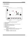
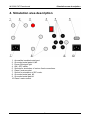
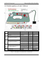
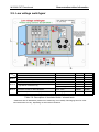
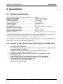
PAT Demoboard
MI 3300
Instruction manual
Version 1.0, Code No. 20 751 070
Distributor:
Manufacturer:
METREL d.d.
Ljubljanska cesta 77
1354 Horjul
Slovenia
web site: http://www.metrel.si
e-mail: [email protected]
Mark on your equipment certifies that this equipment meets the requirements of the EU
(European Union) concerning safety and interference causing equipment regulations
© 2007 METREL
No part of this publication may be reproduced or utilized in any form or by any means
without permission in writing from METREL.
2
MI 3300 PAT Demoboard
Table of contents
1. Introduction ----------------------------------------------------------------------------------------------4
2. Safety warnings ----------------------------------------------------------------------------------------5
3. Description -----------------------------------------------------------------------------------------------6
3.1. Front panel --------------------------------------------------------------------------------------------6
4. Simulation area description ------------------------------------------------------------------------7
5. Demonstration tables information----------------------------------------------------------------8
5.1. General notes: ---------------------------------------------------------------------------------------8
5.2. Portable appliance of class 1 (flatiron) ---------------------------------------------------------9
5.3. Portable appliance of class II – receiver ----------------------------------------------------- 10
5.4. IEC cord --------------------------------------------------------------------------------------------- 11
5.5. Portable appliance of class 1 (extension drum)-------------------------------------------- 12
5.6. Portable appliance of class 1 (coffee machine) -------------------------------------------- 13
5.7. Portable appliance of class 1 (washing machine) ----------------------------------------- 14
5.8. Electrical machine --------------------------------------------------------------------------------- 15
5.9. Low voltage switchgear -------------------------------------------------------------------------- 16
6. Specification------------------------------------------------------------------------------------------- 17
6.1. Technical specification --------------------------------------------------------------------------- 17
6.2. Content of PAT Demoboard set (Ordering code MI 3300) ------------------------------ 17
3
MI 3300 PAT Demoboard
Introduction
1. Introduction
PAT Demoboard is intended for demonstration of electrical equipment safety
management. Typical applications are:
• Presentation of safety management of electrical equipment on seminars,
courses.
• Presentation of typical safety problems on electrical equipment.
• Practical demonstration of measuring instruments (performing tests, making right
connections, analysis of measured results).
Different values of electrical parameters that are usually checked during an electrical
equipment safety test can be simulated. Error states can be switched On or Off.
Electrical parameters that can be simulated are:
• Continuity of equipotential bonding
• Insulation resistance
• Leakage current
• Touch leakage current
• Polarity of cables
• Functional operation
A practically unlimited number of different equipment (portable and handheld
appliances, machines, switchgears) can be simulated by using different demonstration
tables. Eight tables are included in the standard set.
On demand the PAT Demoboard can be simple upgraded with new demonstration
tables (special applications, country design etc) For eventual upgrades contact
METREL or your local distributor.
4
MI 3300 PAT Demoboard
Safety warnings
2. Safety warnings
•
•
•
•
•
•
•
•
•
•
Only qualified personnel who are familiar with the demoboard and measuring
instruments may use PAT Demoboard!
Use only original demonstration tables provided by the manufacturer!
The PAT Demoboard must be considered as a real piece of electrical
equipment. The simulated faults are real ones. Despite of the fact that the
simulated leakage currents are kept at relatively low levels it is strictly
forbidden to touch any of the accessible metal parts inside the simulation area
during the demonstration!
The PAT Demoboard will work only if connected to a properly earthed TN or
TT outlet. The Ready lamp must lit green for normal operation of the
Demoboard.
If red light is blinking and buzzer sounds immediately disconnect the
demoboard from the mains and check the supply connections !
Special care must be taken if performing HV (withstanding) tests. All safety
measures must be considered as if testing real electrical equipment.
Always check that the current of HV test equipment is limited to a low level
(<3.5mA) when performing withstanding tests on PAT Demoboard.
If the equipment is not used in a manner specified by manufacturer, the
protection provided by equipment may be impaired.
Use of Demonstration board in a way not specified in this User Manual could
damage the board.
Do not use Demonstration board in case of any damage noticed!
Only an authorised person may carry out servicing of Demonstration board!
5
MI 3300 PAT Demoboard
Description
3. Description
3.1. Front panel
1.
2.
3.
4.
5.
6.
7.
8.
9.
Mains supply socket for powering the demoboard.
Demoboard data.
Cover holder.
RS232 socket (not used for PAT Demoboard normal operation).
Electrical equipment simulation area.
Groove for placing demonstration tables.
Front plate.
Manufacturer label.
Ready indicator:
Red light – demoboard is not ready.
Blinking red light, buzzer sounds – improper mains connection.
Green light – demoboard is ready for demonstration .
10. Error switches:
Red light on – simulation of error is On.
Red light off – simulation of error is Off.
6
MI 3300 PAT Demoboard
Simulation area description
4. Simulation area description
1. Accessible insulated metal part.
2. Grounded metal parts #1,#2.
3. Power ON signal light.
4. ON / OFF switch.
5. Sockets for simulation of various fixed connections.
6. Class II mains socket.
7. Socket for simulation of IEC cords.
8. Grounded metal part #3.
9. Grounded metal part #4.
10. Class I mains socket.
7
MI 3300 PAT Demoboard
Demonstration tables information
5. Demonstration tables information
5.1. General notes:
• The description tables contain following information:
- Simulated values for normal and error conditions (“Error values”).
- Indicative test results for typical measurements.
- Position where simulated are applied in brackets under “Simulation between
contacts”
• The “Error values” (simulated values, shown in error fields of the tables) in the
description tables are valid only for one fault switched ON at the same time.
If more than one fault is simultaneously the “Error values” are summarized.
•
Individual demonstration tables are recognized on basis of the information stored
in the RFID TAG (legend of errors, simulation values). The TAGs are placed in
the lower left corner of each table. The TAG information is read by the PAT
Demoboard if it is put correctly on the instrument.
•
The values of errors (resistances and capacitances) in description tables are
informative only. The actual inaccuracy is up to ±10%.
•
If the outputs of measuring instruments are not galvanically isolated an additional
error of up to 10% can occur on instrument’s reading.
8
MI 3300 PAT Demoboard
Demonstration tables information
5.2. Portable appliance of class 1 (flatiron)
Simulates
Simulation between contacts
Loose contact of PE conductor
Error 1 Earthed metal part (2) and PE pin on
socket (3)
Insulation fault
Error 2
Error value
Measurement taken
Error value
Error off
Error off
0,02 Ω
Error on
Error on
0,84 Ω
Earth Bond
0,02 Ω
0,84 Ω
Error value
Insulation 500 V DC
Leakage 230 V, 50 Hz
Subleakage
Error value
Insulation 500 V DC
>20 MΩ
>20 MΩ
0,00 mA
0,00 mA
/
>20 MΩ
106 kΩ
0,106 MΩ
2,17 mA
2,17 mA
33 nF
>20 MΩ
L and PE pins on socket (3)
Leakage 230V 50 Hz
0,00 mA
2,12 mA
Subleakage
0,00 mA
2,12 mA
Insulation fault
Error value
>20 MΩ
238 kΩ
Insulation 500 V DC
>20 MΩ
0,238 MΩ
Touch Leakage 230 V
0,00 mA
0,97 mA
Subleakage
0,00 mA
0,97mA
Functional
Functional
/
/
interruptions
interruptions
L and PE pins on socket (3)
Excessive capacitive current
Error 3
Error 4 Accessible isolated metal part (1)
and L pin on socket (3)
Error 5
Functional fault
Functional
Table 5.1: Description of simulated faults / relevant tests
9
MI 3300 PAT Demoboard
Demonstration tables information
5.3. Portable appliance of class II – receiver
Simulates
Simulation between contacts
Insulation fault
Error 1 L pin on socket (2) and accessible
isolated metal part (1)
Error 2
Functional fault
Functional
Error value
Measurement taken
Error value
Insulation 500V DC (probe)
Touch Leakage 230 V AC
Subleakage (probe)
Functional
Functional
Error off
Error off
>20 MΩ
>20 MΩ
0,00 mA
0,00 mA
/
/
Table 5.2: Description of simulated faults / relevant tests
10
Error on
Error on
238 kΩ
0,238 MΩ
0,97 mA
0,97 mA
interruptions
interruptions
MI 3300 PAT Demoboard
Demonstration tables information
5.4. IEC cord
Simulates
Simulation between contacts
Loose contact of PE conductor
Error 1 PE pin on socket (1) and PE pin on
socket (2)
Insulation fault
Error 2
L and PE pins on socket (2)
Crossed L and N wire
Error 3
Polarity
Error value
Measurement taken
Error value
Error off
Error off
0,02 Ω
Error on
Error on
0,84 Ω
Earth Bond
0,02 Ω
0,84 Ω
Error value
Insulation 500 V DC
Polarity
Polarity
>20 MΩ
>20 MΩ
/
/
106 kΩ
0,106 MΩ
L, N crossed
“L, N crossed”
Table 5.3: Description of simulated faults / relevant tests
Note:
For safety reasons there is a serial resistance between L/N pins of socket 1 and socket
2. Some test instruments can therefore return a fail on the Polarity test !
11
MI 3300 PAT Demoboard
Demonstration tables information
5.5. Portable appliance of class 1 (extension drum)
Simulates
Simulation between contacts
Loose contact of PE conductor
Error 1 PE connection on output socket (1) and
PE connection on mains socket (2)
Insulation fault
Error value
Measurement taken
Error value
Error off
Error off
0,02 Ω
Error on
Error on
0,84 Ω
Earth Bond
0,02 Ω
0,84 Ω
Error value
>20 MΩ
106 kΩ
Error 2
Insulation 500 V DC
Leakage 230 V, 50 Hz
Subleakage
Error value
Insulation 500V DC
(probe)
Touch Leakage 230 V AC
Subleakage (probe)
>20 MΩ
0,00 mA
0,00 mA
30 MΩ
0,106 MΩ
2,17 mA
2,17 mA
238 kΩ
13 MΩ
0,237 MΩ
0,00 mA
0,00 mA
0,97 mA
0,97 mA
L and PE pins on socket (1)
Insulation fault
Error 3 Isolated accessible metal part (3) and L,
pin on socket (2)
Table 5.4: Description of simulated faults / relevant tests
12
MI 3300 PAT Demoboard
Demonstration tables information
5.6. Portable appliance of class 1 (coffee machine)
Simulates
Simulation between contacts
Loose contact of PE conductor
Error 1 Earthed metal part (1) and PE pin on socket
(2)
Insulation fault
Error 2
L and PE pins on socket (2)
Excessive capacitive current
Error 3
L and PE pins on socket (2)
Functional fault
Error 4
Functional
Error value
Measurement taken
Error value
Error off
Error off
0,02 Ω
Error on
Error on
0,43 Ω
Earth Bond
0,02 Ω
0,43 Ω
Error value
Insulation 500 V DC
Leakage 230 V, 50 Hz
Subleakage
Error value
Insulation 500 V DC
>20 MΩ
>20 MΩ
0,00 mA
0,00 mA
/
>100 MΩ
106 kΩ
0,106 MΩ
2,17 mA
2,17 mA
33 nF
>100 MΩ
Leakage 230V 50 Hz
0,00 mA
2,12 mA
Subleakage
Functional
Functional
0’00 mA
/
/
2,12 mA
interruptions
interruptions
Table 5.5: Description of simulated faults / relevant tests
13
MI 3300 PAT Demoboard
Demonstration tables information
5.7. Portable appliance of class 1 (washing machine)
Simulates
Simulation between contacts
Loose contact of PE conductor
Error 1 Earthed metal part (1) and PE pin on socket
(2)
Insulation fault
Error 2
L and PE pins on socket (2)
Excessive capacitive current
Error 3
L and PE pins on socket (2)
Functional fault
Error 4
Functional
Error value
Measurement taken
Error value
Error off
Error off
0,02 Ω
Error on
Error on
0,84 Ω
Earth Bond
0,02 Ω
0,84 Ω
Error value
Insulation 500 V DC
Leakage 230 V, 50 Hz
Subleakage
Error value
Insulation 500 V DC
>20 MΩ
>20 MΩ
0,00 mA
0,00 mA
/
>100 MΩ
106 kΩ
0,106 MΩ
2,17 mA
2,17 mA
33 nF
>100 MΩ
Leakage 230V 50 Hz
0,00 mA
2,12 mA
Subleakage
Functional
Functional
0’00 mA
/
/
2,12 mA
interruptions
interruptions
Table 5.6: Description of simulated faults / relevant tests
14
MI 3300 PAT Demoboard
Demonstration tables information
5.8. Electrical machine
Simulates
Simulation between contacts
Loose contact of PE conductor
PE input connection (4) and earthed metal
Error 1 part (2)
PE input connection (4) and earthed metal
part (1)
Insulation fault
Error 2
L (3) and PE (4) input connections
Error 3
Excessive charge on filter capacitors
Error value
Measurement taken
Error value
Error off
Error off
0,02 Ω
Error on
Error on
0,43 Ω
Earth Bond
0,02 Ω
0,43 Ω
Earth Bond
0,02 Ω
0,02 Ω
Error value
Insulation 1000 V DC
Withstanding 1000 V AC
>20 MΩ
>20 MΩ
0,1 mA
4.7nF
100MΩ
cca 0,4 s
/
/
1.88 MΩ
1.880 MΩ
0,6mA
100nF
100MΩ
cca 9 s
interruptions
interruptions
Error value
L and N on input connection (3)
Functional fault
Error 4
Functional
Discharging time*
Functional
Functional
Table 5.7: Description of simulated faults / relevant tests
* Measured with CE Multitester (resistance of measuring circuit 40MΩ). Discharging times for other test
instruments can vary, depending on their internal resistance.
15
MI 3300 PAT Demoboard
Demonstration tables information
5.9. Low voltage switchgear
Simulates
Simulation between contacts
Loose contact of PE conductor
Error 1
PE input connection (1) and earthed metal part (2)
Insulation fault
Error 2
L, (2) and PE connection (3)
Error 3
Error value
Measurement taken
Error value
Earth Bond
Error value
Insulation 1000 V DC
Withstanding 2500 V AC
Excessive charge on filter capacitors
Error value
L and N on input connections (2)
Discharging time*
Error off
Error off
0,02 Ω
0,02 Ω
>20 MΩ
>20 MΩ
0,1 mA
4.7nF
100MΩ
cca 0,4 s
Error on
Error on
0,41 Ω
0,41 Ω
1.88 MΩ
1.880 M Ω
1,4 mA
100nF
100MΩ
cca 9 s
Table 5.8: Description of simulated faults / relevant tests
* Measured with CE Multitester (resistance of measuring circuit 40MΩ). Discharging times for other
test instruments can vary, depending on their internal resistance.
16
MI 3300 PAT Demoboard
Specification
6. Specification
6.1. Technical specification
Protection classification (except simulation area)…Class I
Nominal input voltage: ............................................230 V (+6 %, -10 %)
Optional on request: ...............................................115 V (+6 %, -10 %)
Power consumption: ...............................................15 VA max.
Over-voltage category: ..........................................CAT II 300 V
Frequency range:....................................................45 Hz to 66 Hz
Pollution degree......................................................2
Dimensions (w × h × d)...........................................350 mm x 335 mm x 160 mm
Mass (without accessories) ....................................7 kg
Working temperature range ....................................10 °C ÷ 36 °C
Storage temperature range.....................................-20 °C ÷ +50 °C
Maximum humidity .................................................95 % RH (10 °C ÷ 36 °C) non-condensing
Given simulation resistance and capacitance values (description tables 5.1 to 5.8) are
informative only. Actual inaccuracy is < ±10% of given “Error values”.
If the outputs of measuring instruments are not galvanically isolated an additional error
of up to 10% can occur on instrument’s reading.
6.2. Content of PAT Demoboard set (Ordering code MI 3300)
-
Instrument PAT Demoboard.
8 demonstration tables (iron, receiver, IEC cord, extension drum, coffee machine,
washing machine, switchgear).
CD with User Manual and Electrical equipment testing handbook.
Jumper for shorting L and N connections.
Prolongation cord for demonstration of testing IEC prolongation cords.
Mains supply cable.
Class I mains cable for connecting PAT testers to PAT Demoboard.
Class II mains cable for connecting PAT testers to PAT Demoboard.
Measuring cable for testing discharging time.
Carrying bag for demonstration tables.
Production Verification Data.
17
MI 3300 PAT Demoboard
Specification
18
MI 3300 PAT Demoboard
Specification
19
MI 3300 PAT Demoboard
Specification
20