1
TEMP880S
INSTRUCTION MANUAL
THERMAL SHOCK TEST CONTROLLER
SAMWONTECH
TABLE
1 Installation Instruction
1.1
1.2
1.3
1.4
Instructions(Cautions) for Safety …………………………………………………………………………
The exterior inspection and accessories identification …………………………………………………
Installation ………………………………………………………………………………………………………
Wiring ……………………………………………………………………………………………………………
1
3
5
9
2 Instruction Manual
2.1
2.2
2.3
2.4
2.5
2.6
Setting Button ………………………………………………………………………………………………… 18
How to Enter Setting Value ……………………………………………………………………………… 20
General Operation Setting Flow Chart ………………………………………………………………… 21
Initial Screen ………………………………………………………………………………………………… 22
Main Screen ………………………………………………………………………………………………… 23
Operation Screen …………………………………………………………………………………………… 24
2.6.1 Program stop screen …………………………………………………………………………………… 24
2.6.2 Program preparation screen …………………………………………………………………………… 28
2.6.3 Program operation screen …………………………………………………………………………… 30
2.7 Motion Setting Screen ……………………………………………………………………………………… 33
2.8 Reserve Set Screen………………………………………………………………………………………… 36
2.9 Graph and Graph Record Set Screen …………………………………………………………………… 37
2.10 Pattern Set Screen ………………………………………………………………………………………… 39
2.10.1 File edit screen ………………………………………………………………………………… 42
2.10.2 Time signal setting screen ……………………………………………………………………… 43
2.10.3 Pattern name set …………………………………………………………………………………… 45
2.11 Display Set ……………………………………………………………………………………………… 46
2.12 System Setting Screen …………………………………………………………………………………… 47
2.12.1 Input and input revision for sections………………………………………………………… 48
2.12.2 Control output and transmission setting screen ……………………………………………… 53
2.12.3 Inner signal setting screen ………………………………………………………………………… 57
2.12.4 PID set screen ………………………………………………………………………………………… 59
2.12.5 DO CONFIG setting screen ……………………………………………………………………… 63
2.12.6 Alarm and DI error name setting screen ……………………………………………………… 66
2.12.7 Communication set screen ………………………………………………………………………… 69
2.12.8 Initial display and status display lamp set ………………………………………………………… 70
2.13 Password Input Screen ……………………………………………………………………………………… 72
3 Parameter Setting Table ……………………………………………………………………………………… 73
4 Communication Manual
4.1
4.2
4.3
4.4
Communication Specification ………………………………………………………………………………
Communication Wiring ………………………………………………………………………………………
Communication COMMAND…………………………………………………………………………………
D-REGISTER Explanation …………………………………………………………………………………
79
80
81
89
▪ D-REGISTER TABLE…………………………………………………………………………………………… 96
1st Edition of TEMP880S IM : Sep. 21. 2005
Page 1 / 1
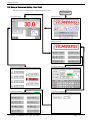
SAMWONTECH
※This is a manual for a Thermal Shock Test Controller(TEMP880S).
1. Installation Instruction
1.1 Instructions(Cautions) for Safety
Thank you for purchasing our Thermal Shock Test Controller(TEMP880S).
This instruction manual explains how to install and use the product.
음Safety Symbol Mark
(A) Represents “Handle with care” or “Caution.” It may cause death, serious injuries, or
damages on the machine if it is violated.
(1) Product : It represents the matters for the protection of the user and product.
(2) User’s manual: In order to prevent the user from receiving electric shocks, it
describes the matters that demand special attention.
(B) Represents a “Grounding Terminal”.
Please make sure the product is earthed when installing and using.
(C) Represents “Additional explanation”
Describes supplementary explanation.
(D) Represents “Reference”.
☞
Describes referential explanation and reference page.
음Cautions for the manual음
(A) Make sure the final users keep this manual, and place it at which it can be easily found.
(B) Use the product after having through full knowledge of the manual.
(C) This manual describes function of the product specifically, and does not warrant matters that
(C) are not included in the manual.
(D) The user should not edit or photo copy any part of the manual without notice.
(E) Some matters on the manual may be changed without notice.
(F) If any errors suchb as poor parts, misexplanation, or omission are found on the manual, please
(C) contact where it was purchased or the business department.
1st Edition of TEMP880S IM : Sep. 21. 2005
Page 1 / 101
SAMWONTECH
음 Caution for the product safety and remodeling음
(A) For the protection and safety of the product and system connected to it, use the product after
(A) having through full knowledge of the manual.
(B) The company is not liable for any damages caused by actions that are inconsistent with the (A)
(A) manual’s instruction or carelessness.
(C) For the protection and safety of the product and system connected to it, install additional (A)
(A) protection or safety circuit on the outside of the product. Interior remodeling or any changes are
(A) forbidden.
(가)
(D) Do not disassemble or remodel. It causes electric shocks, fire, or malfunctioning.
(E) When changing the product parts or supplies, contact our company’s business department.
(F) Inflow of moisture may cause malfunctioning.
(G) A deep impact on the product may cause damages and malfunctioning of the product.
음Exemption from Responsibility음
(A) The company is not liable for any warranty or obligations that are not specified in quality (A) (A)
(A) guarantee qualification of the company.
(B) The company is not liable for any direct or indirect harm of the user or third person, which are
(A) caused by unexpected defect or natural disaster.
음Quality guarantee qualification음
(A) The product is under warranty for one year from purchase. For damages occurred under normal
(A) circumstances as stated in the manual, the product will be repaired without cost.
(B) For damages occurred when the warranty is invalid, it will be repaired under the company (A)
(A) standard at cost.
(C) For the following circumstances, repair is offered at cost even if damages occurred during (A)
(A) warrant period.
(1) Breakdown from user’s mistake or fault (Ex: Initialization due to loss of password)
(2) Breakdown from a natural disaster (Ex: fire, flood, and etc.)
(3) Breakdown from moving after install
(4) Breakdown from disassembling, remodeling or damaging
(5) Breakdown from power supply such as unstable electricity
(6) And others.
(F) Contact the company’s business department if any repair is needed.
1st Edition of TEMP880S IM : Sep. 21. 2005
Page 2 / 101
SAMWONTECH
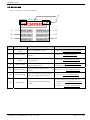
1.2 The exterior inspection and accessories identification
▶ Check the exterior of the product to make sure the product is not damaged when it is first purchased. ▶
▶ Also, check the following matters.
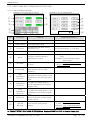
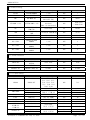
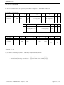
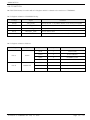
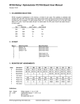
1.2.1 Features of ordered product confirmation
▶ Confirm the obtained product is identical with what you order.
▶ How to confirm: Confirm feature code of label on the right side of the box or left side of the product ▶
▶ case.
Model
TEMP880S
Feature
Code
Appendix
Code
UDC
Contents
-
1
I/O1 BOARD (10 POINT : basis)
→ 24V SMPS internally equipped
-
2
I/O2 BOARD (10 POINT : addition)
0
RS232C (basis)
1
RS485 (option)
/UDC
UDC100 (option)
☞ In the case of generic model, the code is TEMP880S-10 (I/O 10POINT + RS232C).
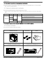
1.2.2 Contents confirmation
▶ Confirm the following contents are included.
TEMP880S mainframe
I/O1 BOARD + 30 Pin Cable
→ 24V SMPS included(RELAY driving)
1st Edition of TEMP880S IM : Sep. 21. 2005
Fixed mount
Manual
I/O2 BOARD + 14 Pin Cable
→ Included only for TEMP880S-20 or -21
Page 3 / 101
SAMWONTECH
1.2.3 Processing of damaged product
▶ Contact where the products are purchased or the company’s business department if you find any
▶ missing or damaged parts.
Lifetime of the parts in the controller
▶ Check replacement period for the following non-durable parts and replace them before the
▶ period exceeds.
■
■
■
■
FUSE
BACKLIGHT
RELAY
BATTERY
SR-5:630mA/250VAC equivalent product
JQ1P-DC24V equivalent product
ER3VT(3.6V) 1/2AA equivalent product
: semi-permanent
: 10,000 ~ 15,000 HOUR
: less than ON/OFF 300,000 times
: less than 200,000 HOUR
☞ For batteries, use the identical product or the ones with same capacity to prevent explosion.
☞ Also, separate used batteries from other garbage when you dispose them.
1st Edition of TEMP880S IM : Sep. 21. 2005
Page 4 / 101
SAMWONTECH
1.3 INSTALLATION
1.3.1 INSTALLATION PLACE AND ENVIRONMENT
음Cautions for installment place and environment
(A) To prevent from getting electric shocks, turn on the product after it is installed on the panel.
(B) Do not install the product under the following environment.
■ Place where people can touch the ground connection without noticing.
■ Place exposed directly to machinery vibration or shock.
■ Place exposed to corrosion or combustion gas.
■ Place where temperature fluctuates intensely.
■ Place where temperature is extremely high(over 50℃) or low (below 10℃)
■ Place exposed to the direct sun ray.
■ Place affected a lot by a electric wave.
■ Humid place (humidity is over 85%)
■ Place where keeps inflammable things.
■ Place where contains a lot of dust or salt.
■ Place affected a lot by an ultraviolet ray.
☞ Even though the product case is SPCC-SD and BEZEL is made of ABS/PC noninflammable material, do ☞
☞ not install the product around inflammable things. Especially, do not place the product on a inflammable
☞ material.
1.3.2 CAUTION FOR INSTALLATION
음Caution for installation
(A) Do not place machines or wires that cause noise.
(B) Keep the product within 10∼50℃, 20∼90%RH(dew free. Especially, keep it away from things
(B) that generate heat extremely.
(C) Do not install the product on a slant..
(D) Keep the product within-25∼70℃, 5∼95%RH(dew free). When operating it below 10℃, warm it
(B) up enough before use it.
(가)
(E) When wiring, turn off all power source.
(F) This product operates at 100∼240VAC, 50/60Hz 15VAmax. Using power out of this range may
(B) cause fire or electric shocks.
(G) Do not operate with wet hands. There is danger of an electric shock.
(H) Follow instructions to prevent fire, electric shocks, and damage.
(I) Install and use the product as the manual instructs.
(J) For ground connection, follow the manual. However, never earth on water pipe, gas pipe, phone
(J) cable, or lightening rod. There is danger of explosion and fire..
(K) Do not turn on the product before the parts are connected to each other. It causes damage and
(K) breakdown.
(L) Do not block the radiator of the product. Blocking the radiator causes breakdown.
(M) Do not install I/O Relay Board on a slant. Install it inside of a thermo humidistat. Use it by fixing
(M) after tightly cramping it with a bolt and nut on a hole for fixation that is open on the board.
(N) Overvoltage protection is Category II, and environment for usage is Degree Ⅱ.
1st Edition of TEMP880S IM : Sep. 21. 2005
Page 5 / 101
SAMWONTECH
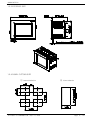
1.3.3 EXTERIOR SIZE
1.3.4 PANEL CUTTING SIZE
1
○
General Adhesion
1st Edition of TEMP880S IM : Sep. 21. 2005
2
○
Close Adhesion
Page 6 / 101
SAMWONTECH
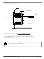
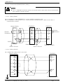
1.3.5 HOW TO ADHERE MOUNT
PANEL
FIXED MOUNT
DRIVER
INSERT DIRECTION
( ) : inch
Panel Thickness: 1 (0.04) ~ 10 (0.39) mm
1
○
2
○
3
○
3
○
Cut panel that you wish to set up. (1.3.4. Refer to PANEL CUTTING SIZE)
Insert the product from the back side into the installing hole as figure above.
Fix the mainframe using fixed mount located on left and right side of the mainframe
(by the use of a driver).
Cautions on the fixation of a fixed mount
▶ When you fix the fixed mount, do not tighten it intensely.
1st Edition of TEMP880S IM : Sep. 21. 2005
Page 7 / 101
SAMWONTECH
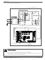
1.3.6 CUTOFF CIRCUIT INSTALLATION
Chamber Case
Circuit Breaker
(Circuit Breaker)
~
○
● N1
N2 ●
● L1
L2 ●
● G1
G2 ●
Relay Contact Output
(Relay Contact Output)
24V
(Use for IO2 option)
Power
SSR/SCR, Recorder
(Control, Transmission Output)
Contact Input
(접점입력:DI)
Ground Connection
▶ You must earth on the electric wiring of the power source part.
▶ Power source should be supplied to the inner part of TEMP 880S through the power cutoff.
▶ Use the power cutoff after it is earthed evenly.
1st Edition of TEMP880S IM : Sep. 21. 2005
Page 8 / 101
SAMWONTECH
1.4 Wiring
Caution
▶ Using a tester, make sure all power sources are turned off and wiring cable is not active.
▶ Do not touch the terminal when the wire is active due to potential electric shocks.
▶ Wire after the main power source is turned off.
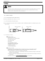
1.4.1 HOW TO WIRE
1.4.1.1 Recommended Power Cable Feature
▶ Vinyl Insulated Wire KSC 3304 0.9~2.0 ㎟
1.4.1.2 Recommended Terminal Feature
Above Φ3.0mm
Less than 5.8mm
Less than Φ5.8mm
▶ Use compression terminal, which is suitable for M3.5 SCREW and adhered to insulated sleeve as the
▶ figure below.
Above 3.0mm
1.4.1.3 Solution for Noise
■ Cause of noise
(A) Relay and contact
(B) Solenoid Coil, Solenoid Valve
(C) Power source line
(D) Induced load
(E) Inverter
(F) Commutator of motor
(G) Phase angle control SCR
(H) Wireless communicator
(I) Welding machine
(J) High voltage lighter
■ Solution for noise
■ Pay attention to the following matters to avoid the source of noise when you wire.
(A) Wire input circuit with space from the power and ground connection circuit.
(B) Use shield wire for noise from power cut induction.
(B) Please connect shield wire to a grounding connection terminal according to needs while
(B) avoiding 2 type grounding.
(C) Please lay wires after twisting the input wire with a narrow interval according to electronic
(C) inducement.
(D) Refer to the use of 1.4.2.9 supplementary RELAY as you need.
1st Edition of TEMP880S IM : Sep. 21. 2005
Page 9 / 101
SAMWONTECH
1.4.2 TERMINAL WIRING DIAGRAM
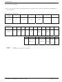
1.4.2.1 TEMP880S Mainframe Terminal
STANDARD : TEMP880S-10(RS232C + I/O1)
OPTION1 : TEMP880S-11(RS485 + I/O1)
RS232C
RS485
RS485
RTX+
RTXSG
Add UDC option : TEMP880S-10/UDC
Add UDC Option : TEMP880S-11/UDC
OPTION2 : TEMP880S-20(RS232C + I/O1 + I/O2)
OPTION3 : TEMP880S-21(RS485 + I/O1 + 1/O2)
RS232C
I/O2 LINK
RS485
RS485
I/O2 LINK
RTX+
RTXSG
Add UDC Option : TEMP880S-20/UDC
1st Edition of TEMP880S IM : Sep. 21. 2005
Add UDC Option : TEMP880S-21/UDC
Page 10 / 101
SAMWONTECH
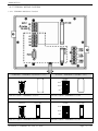
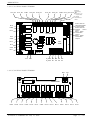
1.4.2.2 I/O1 RELAY BOARD TERMINAL
RLY7_NC
RLY7_NO
COM4
RLY8_NC
RLY8_NO
RLY9_NC
RLY9_NO
RLY6
COM5
External
connecting
RLY10_NC RLY10_NO
switch RLY 10
→ It operates
by being
connected to
“AND”
AOUT1- AOUT1+
Temperature(heatin
g) control output
AOUT2- AOUT2+
Freezing
control
output
RET1- RET1+
Transmission
output 1
RET2- RET2+
Transmission
output 2
P10
COM3
RLY5
I/O1 BOARD
RLY4
COM2
I/O1
LINK
RLY3
RLY2
COM1
RLY1
L N FG
220V AC
+24V
GND
DI_COM
DI_COM
DI8
DI7
DI6
DI5
DI4
DI3
DI2
DI1
1.4.2.3 I/O2 RELAY BOARD TERMINAL
GND
I/O2
LINK
COM4
RLY20
RLY19
+24V
I/O2 BOARD
COM3
RLY18
RLY17
1st Edition of TEMP880S IM : Sep. 21. 2005
COM2
RLY16
RLY15
RLY14
COM1
RLY13
RLY12
RLY11
Page 11 / 101
SAMWONTECH
1.4.2.4 Wiring Ground Connection and Power Source
▶
▶
▶
▶
Wire ground connection with cable thicker than 2 ㎟ and ground connection resistance below 100Ω
(over 3-type ground connection). Also, ground connection cable should be wired within 20m.
Earth 1 point from ground connection terminal, and do not wire passing ground connection terminal.
Use vinyl insulation wire(KSC 3304) or cable that has similar capacity for the power source wiring.
L
100~240V AC
50/60Hz
N
FG
Class 3 Ground
You must earth FRAME GROUND(FG).
1.4.2.5 WIRING ANALOG INPUT
Caution
▶
▶
▶
▶
▶
▶
▶
▶
Turn off the mainframe of Temp880S and external power source due to potential electric
shocks.
Use input wire that is adhere to shield. Also, shield should be done as 1point ground
connection.
Wire measuring input signal line leaving a space from the power circuit or ground
connection circuit..
Use wire that has little conduct resistance and doesn’t have resistance difference among
three wires.
DC VOLTAGE INPUT
+
TC
INPUT
-
TEMP880S
Class 3 Ground
1st Edition of TEMP880S IM : Sep. 21. 2005
Page 12 / 101
SAMWONTECH
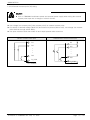
1.4.2.6 Control Output (Voltage pulse Output, Electric Present Output) and Wiring Transmission Output
Caution
▶ Turn off TEMP880S mainframe power and external power supply when wiring the control
output (SSR, SCR) and transmission output due to danger of electric shocks.
▶ Be careful with output polarity. Incorrect connection causes damage to the mainframe.
▶ Use output wire that has shield attached. Shield should be done as 1point ground
▶connection.
Temperature(heating) Control Output Wire
(SSR/4~20mA)
Cooling Control Output Wire (SSR/4~20mA)
CONTROL
VALVE
CONTROL
VALVE
SHIELD
ACTUATOR
SHIELD
+
AOUT1+
-
AOUT1-
ACTUATOR
+
AOUT2+
-
AOUT2I/O1 BOARD
I/O1 BOARD
Class 3 Ground
Class 3 Ground
SSR : 12VDC min, 600Ω min
SCR : 4~20mADC min, 600Ω max
SSR : 12VDC min, 600Ω min
SCR : 4~20mADC min, 600Ω max
Transmission Output 1 Wire (4~20mA)
Transmission Output 2 Wire (4~20mA)
4~20 mADC
600Ω max
4~20 mADC
600Ω max
SHIELD
RECEIVER
(RECORDER)
SHIELD
+
RET1+
-
RET1-
RECEIVER
(RECORDER)
+
RET2+
-
RET2I/O1 BOARD
I/O1 BOARD
Class 3 Ground
1st Edition of TEMP880S IM : Sep. 21. 2005
Class 3 Ground
Page 13 / 101
SAMWONTECH
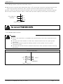
1.4.2.7 External Contact Point Output (RELAY) Wire
Caution
▶ Turn off TEMP880S mainframe power and external power supply when wiring the external
▶ contact point output due to danger of electric shocks.
Below 30VDC 5A, Below 250VAC 5A
Below 30VDC 5A, Below 250VAC 5A
Below 30VDC 5A, Below 250VAC 5A
RLY1
RLY3
RLY5
RLY2
RLY4
RLY6
COM1
COM2
COM3
I/O1 BOARD
I/O1 BOARD
I/O1 BOARD
NO(Normal Open):Below 30VDC 5A,Below 250VAC 5A
NC(Normal Close):Below 30VDC 1A, Below 250VAC 2A
NO(Normal Open):Below 30VDC 5A, Below 250VAC 5A
NC(Normal Close):Below 30VDC 1A, Below 250VAC 2A
RLY7_NC
RLY9_NC
RLY7_NO
RLY9_NO
COM4
COM5
RLY8_NC
RLY10_NC
RLY8_NO
RLY10_NO
P10
I/O1 BOARD
Below 30VDC 5A, Below 250VAC 5A
I/O1 BOARD
Below 30VDC 5A, Below 250VAC 5A
RLY11
RLY14
RLY12
RLY15
RLY13
RLY16
COM1
COM2
I/O2 BOARD
Below 30VDC 5A, Below 250VAC 5A
I/O2 BOARD
Below 30VDC 5A, Below 250VAC 5A
RLY17
RLY19
RLY18
RLY20
COM3
COM4
I/O2 BOARD
I/O2 BOARD
1st Edition of TEMP880S IM : Sep. 21. 2005
Page 14 / 101
SAMWONTECH
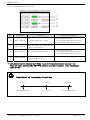
1.4.2.8 External contract point (DI) wiring
Caution
▶ Turn off TEMP880S mainframe power and external power supply when wiring the external
▶ contact point input due to danger of electric shocks.
▶ Use voltage free contact point (relay contact point) for external contact point.
▶ For turned of terminal voltage (about 5V) and turned on present (about 1mA), use voltage free contact
▶ point that has enough switch ability.
▶ Use open collector which has under 2V and 100μA present when turned on
RELAY Contact Point Input
DI1
DI2
•
•
•
TRANSISTOR Contact Point Input
DI1
DI2
•
•
•
DI8
DI8
DI_COM
I/O1 BOARD
1st Edition of TEMP880S IM : Sep. 21. 2005
DI_COM
I/O1 BOARD
Page 15 / 101
SAMWONTECH
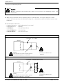
1.4.2.9 Use of Supporting RELAY
Caution
▶ When resistance load exceeds relay feature of the product, use supporting relay to turn
on/off load.
▶ When using inductance load as supporting relay or solenoide valve, use surge suppressor, sparks
▶ removal as circuit and insert CR filter (when using AC) or diode(when using DC) parallel to prevent relay
▶ breakdown.
▶ Recommended CR FILTER
→ Sungho Electronics
: BSE104R120 25V (0.1μ+120Ω)
→ HANA PARTS CO. : : HN2EAC
→ 松尾電機(株)
:: CR UNIT 953, 955 etc
→ (株)指月電機製作所 :: SKV, SKVB etc
→ 信英通信工業(株)
:: CR-CFS, CR-U etc
DC RELAY
EXTERNAL DC POWER
METER
R
RELAY
(Use RELAY COIL that is below ground
connection capacity of controller)
DIODE
(Connect to RELAY COIL
directly.)
AC RELAY
EXTERNAL ALTERNATING POWER
METER
R
RELAY
(Use RELAY COIL that is below ground
connection capacity of controller)
1st Edition of TEMP880S IM : Sep. 21. 2005
CR FILTER
(Connect to RELAY COIL
directly.)
Page 16 / 101
SAMWONTECH
1.4.2.10 Communication(RS485/RS232C) Wiring
Caution
▶ Turn off TEMP880S mainframe power and external power supply when wiring communication
▶ due to danger of electric shocks.
1.4.2.10.1 Wiring RS485
▶ It is possible for slave (TEMP880S) to connect multidrop maximum of 99.
▶ For TEMP880S or MASTER (PC, PLC), connect division resistance(200Ω 1/4W) on both sides of
▶ communication channel.
Master Station
Division
Resistance
TEMP880S
TEMP880S
RTX+
RTX+
RTX+
RTX-
RTX-
RTX-
SG
SG
SG
Division
Resistance
SHIELD
TERMINAL BOARD
Class 3 Ground
TERMINAL BOARD
Class 3 Ground
1.4.2.10.2 Wiring RS232C
▶ CONNECTOR : Wiring with D-Sub 9 PIN
Master Station
TEMP880S
RD
2
2 RxD
TD
3
3 TxD
RTS
7
CTS 8
SG
5
5 SG
SHIELD
D-Sub 9Pin Female
1st Edition of TEMP880S IM : Sep. 21. 2005
Page 17 / 101
SAMWONTECH
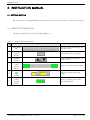
2. INSTRUCTION MANUAL
2.1 SETTING BUTTON
▶ This product is a programmable controller that is set up as touch screen for a user to use easily.
2.1.1 BASIC SETTING BUTTON
▶ Basic control button is as the following table(1-1).
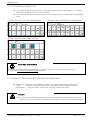
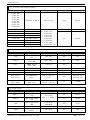
Table 1-1. BASIC SETTING BUTTON
Button Type
1
2
3
4
5
6
Upper Main
Bar
General
Active
Button
Page
Up/Down
Button
Setting
Value
Choice
Button
Setting
Value
Input
Button
Setting
Value
Change
Button
1st Edition of TEMP880S IM : Sep. 21. 2005
Button Explanation
Change screen according to left
and right touch.
For general action or choice.
Used for switching pages in the
same screen.
Used for choosing setting value.
Switch to setting value input
screen.
Used for changing more than
two setting values.
Page 18 / 101
SAMWONTECH
2.1.2 SETTING VALUE INPUT KEY
▶
▶
▶
▶
If you press setting value input button on general setting button as above(table 1-1), setting
value input key appears and you can enter data.
If you enter data that exceeds input range, error message appears(“-LIMIT ERR”) with beeping
sound.
1
○
INPUT KEY ONLY FOR SETTING NUMBERS
3
○
INPUT KEY FOR TIME SIGNAL SETTING
2
○
INPUT KEY FOR SETTING DI ERROR NAMES
Touch Key Lock Removal
▶ Setting value does not get entered when key lock is turned on, enter after turn off key lock.
☞ Refer to 2.7 ACTION SETTING SCREEN for detail.
2.1.3 VALIDITY FOR SETTING BUTTON AND SETTONG VALUE
▶ The product is made to check validity of entered setting value by making beeping noise.
☞ "beep"
: when press general setting button and setting value is entered correctly.
☞ "beep-bleep" : Data entered by setting value input key exceeds the range.
Caution
▶ Do not press general setting button and setting value input key with sharp thing(such as
▶ pencil) or nail. Or, the product may show bad operation or touch swich may be damaged.
1st Edition of TEMP880S IM : Sep. 21. 2005
Page 19 / 101
SAMWONTECH
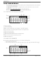
2.2 HOW TO ENTER SETTING VALUE
▶
▶
▶
▶
▶
▶
All input data for the product is set by input key such as setting value input key, test name input
key, and time signal input key.
Setting value input key(Table 1-1) appears when you press input button, and you can enter
input value.
Refer to 2.10.2 TIME SIGNAL SETTING for time signal input key.
Refer to 2.10.3 TEST NAME SETTING for test name setting input key.
2.2.1 FUNCTION OF SETTING VALUE INPUT KEY
9
○
1
○
8
○
3
○
2
○
4
○
7
○
6
○
5
○
1 Shows parameter
○
2 Shows setting range
○
3 When exceeds setting range, error message (“-LIMIT ERR”) appears.
○
4 Use this button to stop entering data and return to the original screen
○
5 When erase all input data.
○
6 When enter decimal points..
○
7 When save entered data and restore the original screen.
○
8 When edit entered data, erase data one by one.
○
9 When enter signs(+/-).
○
2.2.2 HOW TO SET PARAMETER
▶ If you wish to setting value from-50.00 to -12.57, take the following steps.
→ Press setting value input button.
1 →○
2 →○
3 →○
4 →○
5 →○
6 ), and finally "ENT" key(○
7 )
→ Press following numbers with such order (○
3
○
1
○
2
○
7
○
5
○
6
○
1st Edition of TEMP880S IM : Sep. 21. 2005
4
○
Page 20 / 101
SAMWONTECH
2.3 General Operation Setting Flow Chart
▶ The picture below roughly diagrammatize the flow.
Input Power
[Program Stop]
[Initial Screen]
[Main Screen]
[DI Error Occurred]
[Program Setting]
[System Setting]
[Password Setting]
1st Edition of TEMP880S IM : Sep. 21. 2005
Page 21 / 101
SAMWONTECH
2.4 Initial Screen
▶ Screen that displays when initially input power.
▶ It moves to 2.6 OPERATION SCREEN after three seconds automatically.
Diagram 2-1. Initial Screen
1
○
2
○
3
○
4
○
No.
Instruction
Contents
1
○
Version
Indicates version info of the product.
2
○
Co.Name
Indicates name of the company.
3
○
Phone
Indicates contact phone number.
4
○
Webpage
Additional Explanation
▶ V1R0 → VERSION 1, REVISION 0
▶ It may be edited at 2.12.8 INITIAL
▶ DISPLAY SETTING.
Indicates webpage address.
1st Edition of TEMP880S IM : Sep. 21. 2005
Page 22 / 101
SAMWONTECH
2.5 Main Screen
▶ It is a center of screen movement.
7
○
Diagram 2-2. Main Screen
A
○
B
○
1
○
4
○
2
○
5
○
3
○
6
○
No.
Instruction
1
○
Operation
Screen
2
○
Contents
Additional Explanation
Shifts to operation screen.
▶ Refer to 2.6 OPERATION SCREEN
Motion Setting
Shifts to function and fixed setting
screen.
▶ Refer to 2.7 Motion SETTING
3
○
Reserved
Setting
Shifts to present time and reserved
setting screen.
▶ Refer to 2.8 RESERVED SETTING
4
○
Graph Display
Shifts to graph display and graph
record setting screen.
▶ Refer to 2.9 GRAPH AND GRAPH
▶ RECORD SETTING
5
○
Pattern Setting
Shifts to pattern setting menu
screen.
▶ Refer to 2.10 PATTERN SETTING
6
○
Screen Setting
Shifts to tuning key display setting
and screen light control screen.
▶ Refer to 2.11 SCREEN CHOICE
▶ After pressing ○
A , press ○
B to
7
○
Hidden Key
Shifts to system internal setting
screen.
1st Edition of TEMP880S IM : Sep. 21. 2005
▶ display for 2.13 PASSWORD INPUT
▶ screen
▶ Refer to 2.12 SYSTEM SETTING
Page 23 / 101
SAMWONTECH
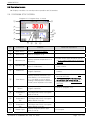
2.6 Operation Screen
▶ Displays condition for actual product operation and information.
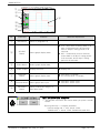
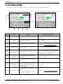
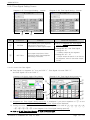
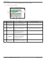
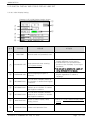
2.6.1 PROGRAM STOP SCREEN
Diagram 2-3. Program Stop -1screen
2
○
1
○
3
○
4
○
5
○
12
○
13
○
14
○
7
○
6
○
8
10
9
11
○
○
○
○
No.
Instruction
1
○
Main Button
Shifts to 2.5 MAIN SCREEN.
2
○
Next Button
Shifts to (Diagram 2-4).
3
○
Laboratory PV
Displays present temperature of a
laboratory.
▶ Proper sensor type should be set up
▶ in 2.12.1 INPUT AND INPUT REVISION
▶ SETTING.
4
○
Laboratory MV
Displays present control output
value of a laboratory.
▶ P.OUT output occurs when it is not
▶ under control.
5
○
Pattern No.
Displays pattern number to start
program operation.
▶ Press button to set operation pattern
▶ number.
6
○
Time Button
Displays present time and if you
press button, LCD screen turns
off. If you wish to turn on when
nothing is displayed but operated
normal, press anywhere on screen.
▶
▶
☞
☞
▶
▶
7
○
Operation
Button
Displays a confirm box to start
program operation.
▶ Refer to (Diagram 2-5).
8
○
9
○
10
○
11
○
Contents
High
Temperature
TSP
Normal
Temperature
TSP
Low
Temperature
TSP
Displays high temperature
TSP(Target Set Point) of program
which is set up.
Displays normal temperature
TSP(Target Set Point) of program
pattern which is set up.
Displays low temperature
TSP(Target Set Point) of program
pattern which is set up.
Pattern Type
Displays program pattern type
which is set up.
1st Edition of TEMP880S IM : Sep. 21. 2005
Additional Explanation
Set automatic turn off time in 2.7
MOTON SETTING.
For long durability of the back light,
ten munutes are initially set up.
Set present time in 2.8 RESERVED
SETTING.
▶ Four types
Page 24 / 101
SAMWONTECH
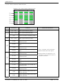
12
○
13
○
14
○
High
Temperature
Room Operation
Lamp
Normal
Temperature
Room Operation
Lamp
Low
Temperature
Room Operation
Lamp
Displays red lamp when a heat
shock tester is operating high
temperature part.
▶ Turns off when preheating.
Displays yellow lamp when a heat
shock tester is operating normal
temperature part.
Displays blue lamp when a heat
shock tester is operating low
temperature part.
▶ Turns off when preheating.
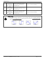
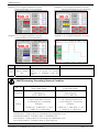
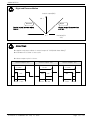
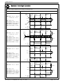
Pattern Type
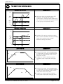
☞ There are two pattern types(Type-1,2) as for Elevator Type, and four pattern types(Type☞ 1,2,3,4) as for Damper Type. The pattern type can be set up in 2.10 PATTERN SETTING.
☞ Refer to 2.10 PATTERN SETTING.
Type-1
1st Edition of TEMP880S IM : Sep. 21. 2005
Type-2
Type-3
Type-4
Page 25 / 101
SAMWONTECH
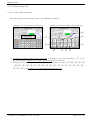
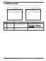
Diagram 2-4. Program Stop-2 screen
1
○
2
○
3
○
4
○
5
○
6
○
7
○
No.
Instruction
1
○
Next Button
Contents
Additional Explanation
Shifts to (Diagram2-3)
▶
▶
▶
▶
▶
▶
▶
▶
STP : Stops after recording data for 8
days if saving period is 60 seconds,
and for 4days if saving period is 40
seconds.
RPT : Continuously record. Records
recent data for 8 days if saving period
is 60 seconds, and 4 days if saving
period is 30 seconds.
2
○
STP/RPT
Button
Select graph display state.
3
○
Delete Button
Delete graph display data.
4
○
Graph Display
Display Room PV
▶ Display red
5
○
RON/ROF
Button
Select graph display save.
▶ Save RON : PV Graph
▶ Do not save ROF : PV Graph
6
○
30S/60S Button
Select graph save cycle.
▶ Save 30S : 30sec cycle
▶ Save 60S : 60sec cycle
7
○
Back/Next
Button
Shifts to back/next stage of X
axis (time scale)
MOTION CONFIRM WINDOW
☞ This window reconfirms the motion when you press a certain
☞ button.
EX) Program stop ↔ Program operation,
EX) Defrost setting ON ↔ OFF, HOLD, STEP,
EX) TUNING OFF ↔ HOLD, STEP, TUNING ON, AND ETC.
1st Edition of TEMP880S IM : Sep. 21. 2005
Page 26 / 101
SAMWONTECH
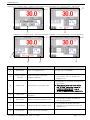
Diagram 2-5. Program Stop – Operation performing confirm Diagram 2-6. Program Stop – Pattern end
1
○
1
○
2
○
3
○
Diagram 2-7. Program Stop – Reserved operation Diagram 2-8. Program Stop – Defrost Operation
1
○
1
○
4
○
5
○
No.
Instruction
1
○
Next Button
2
○
Action Confirm
Window
7
○
6
○
Contents
Additional Explanation
Shifts to (Diagram2-4).
▶ Used only forTEMP880
Asks if you wish to perform
program operation.
▶ Operation starts if you press “YES”.
▶ If you press “NO”, it restores as
▶ diagram 2-3.
▶
▶
☞
☞
☞
☞
Disappears if you press anywhere on
the screen.
Even though relay and time, which
are “PTEND” parameter are set in
2.12.5 DO CONFIG SET, relay is
turned off when message disappears.
3
○
Pattern End
Blinks when set program ends.
4
○
Start Time
Displays start time for reserved
operation.
5
○
Reservation
Blinks if reserved operation is set.
▶ Set operation pattern numbers by
▶ pressing the button.
6
○
Cancel Button
Cancels reserved operation state.
▶ If you press the button reserved
▶ operation is canceled and return as
▶ diagram 2-3.
7
○
Close Button
Closes the defrost condition
1st Edition of TEMP880S IM : Sep. 21. 2005
Page 27 / 101
SAMWONTECH
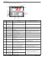
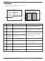
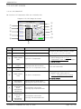
2.6.2 PROGRAM PREPARATION SCREEN
2
○
Diagram 2-9. Program Preparation – 1screen
1
○
3
○
4
○
6
○
7
○
5
○
15
○
12
○
8
○
9
○
10
○
11
○
No.
Instruction
1
○
Program Name
2
○
State
Information
Display
Displays present state information.
3
○
Next Button
Shifts to diagram 2-10.
4
○
Laboratory SP
Displays present SET POINT of
laboratory.
5
○
Laboratory MV
Displays present control output
value of laboratory.
6
○
Cycle
7
○
SEG Operation
8
○
SEC Time
9
○
Operation Time
Displays the whole operation time
up to the present.
10
○
Hold Button
Hold on to the set point of the
present temperature or hold it off.
11
○
Step Button
End the present segment and
shifts to the next segment.
12
○
End Button
Displays a confirming box to to
end the program operation.
13
○
14
○
High
Temperature
Part LAMP
Normal
Temperature
Part LAMP
13
○
14
○
Contents
Additional Explanation
Displays program name which is
set up.
▶ P.OUT output occurs when it is not
▶ under control.
Displays the number of repetition
of pattern concerned.
Displays operation time of zone
concerned.
Displays time set up of zone
concerned.
Displays operation state of high
temperature part.
Displays operation state of normal
temperature part.
1st Edition of TEMP880S IM : Sep. 21. 2005
▶ Whole operation time > Start
▶ accumulation again from 0000H00M
▶ when 9999H59M.
▶ Starts operation ignoring WAIT when it
▶ is “STEP” under WAIT.
▶
▶
▶
▶
▶
Lamp in zone concerned blinks when in
preheating and precooling, and zone
completed of preheating and
precooling stops blinking and maintain
lamp “off”.
Page 28 / 101
SAMWONTECH
15
○
Low
Temperature
Part LAMP
Displays operate
temperature part.
state
of
Diagram 2-10. Program Preperation – 2screen
1
○
2
○
3
○
4
○
5
○
6
○
7
○
8
○
low
Diagram 2-11. Program Preparation – 3screen
9
○
10
○
11
○
No.
Instruction
1
○
Laboratory PV
Displays pesent temperature of
laboratory.
2
○
Laboratory MV
Displays present control output
value of laboratory.
3
○
4
○
5
○
High
Temperature
Room TSP
Normal
Temperature
Room TSP
Low
Temperature
Room TSP
Contents
Additional Explanation
▶ P.OUT output occurs when it is not
under control.
Displays high temperature room
TSP value.
Displays normal temperature room
TSP value.
▶
▶
▶
▶
Turn on a lamp in zone concerned
when preheating and precooling, and
turn off a lamp in zone completed of
preheating and precooling.
Displays low temperature room
TSP value.
Displays the number of repetition
of pattern concerned.
6
○
Cycle
7
○
Remaining Time
Displays remaining time of the
total operation time.
8
○
Operation Time
Displays the entire process time
operated up to the present.
9
○
High
Temperature
Room
PV, SP, MV
10
○
Low
Temperature
Room
PV, SP, MV
11
○
Condition
Signlay Lamp
Displays PV(temperature measure
value), SP(preheating setting
temperature), MV(control output
value) of the present high
temperature room.
Displays PV(temperature measure
value), SP(precooling setting
temperature), MV(control output
value) of the present high
temperature room.
ON : Showing red light
OFF: Showing dark grey light
1st Edition of TEMP880S IM : Sep. 21. 2005
▶ Refer to 2.12.8 INITIAL SIGN AND
▶ CONDITION SIGH LAMP SETTING
☞ Able to display total 16 lamps.
Page 29 / 101
SAMWONTECH
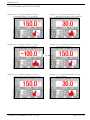
2.6.3 PROGRAM OPERATION SCREEN
Diagram 2-12. Program Operation–1screen
(High temperature room operation)
Diagram 2-13. Program Operation–1screen
(Normal temperature room operation)
Diagram 2-14. Program Operation-1screen
(Low temperature room operation)
Diagram 2-15. Program Operation-1screen
(Turning key display)
1
○
Diagram 2-16. Program Operation-1screen
(when turning high temperature room)
1st Edition of TEMP880S IM : Sep. 21. 2005
Diagram 2-17. Program Operation-1screen
(when holding)
Page 30 / 101
SAMWONTECH
Diagram 2-18. Program Operation–2screen
(High temperature room operation)
Diagram 2-19. Program Operation-2screen
(Normal temperature room operation)
Diagram 2-20. Program Operation-2screen
(Low temperature room operation)
Diagram 2-21. Program Operation-3screen
No.
Instruction
Contents
Additional Explanation
1
○
AUTO TUNING
KEY
Displayed when setting a tuning
button of a screen for screen
selection of (Diagram 2-40) as
DISP.
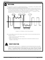
WAIT(Preheating, Precooling) Removal Condition
WAIT SP
No Setting
Setting
Preheating
Preheating
Precooling
Precooling
High Temperature Room
(HIGH TEMP ZONE)
Low Temperature Room
(LOW TEMP ZONE)
High Temperature Room PV =
Preheating SP
(H.PV = WAIT SP)
Preheating SP – Preheating Deviation
≤ High Temperature Room PV
≤ Preheating SP + Preheating
Deviation
Low Temperature Room PV =
Precooling SP
(L.PV = WAIT SP)
Precooling SP – Precooling Deviation
≤ Low Temperature Room PV
≤ Precooling SP + Precooling
Deviation
(H.WAIT SP – H.WSP.DEV ≤ H.PV
≤ H.WAIT SP + H.WSP.DEV)
(L.WAIT SP – L.WSP.DEV ≤ L.PV
≤ L.WAIT SP + L.WSP.DEV)
SP : Setting value for preheating high temperature room
Deviation : Deviation value for preheating SP
SP : Setting value for precooling low temperature room
Deviation : Deviation value for precooling SP
1st Edition of TEMP880S IM : Sep. 21. 2005
Page 31 / 101
SAMWONTECH
AUTO TUNING
▶
▶
▶
▶
▶
▶
▶
Auto tuning is a function for automatically adjusting P, I, D parameter to the optimal condition
suitable for a system for controlling a heat shock tester.
Auto tuning can be performed only when thermal shock tester is running, and be done for a
aboratory currently operated. For example, when auto tuning is operated during the operation
of the present high temperature room. When auto tuning is completed, P, I, D values
automatically calculated by auto tuning are automatically set in P, I, D parameter of high
temperature part of laboratory and of high temperature room.
AT start
AT end
AT in high
AT start
AT end
AT in low
Diagram 2-22. Example of Auto Tuning Operation
▶ It is impossible to perform auto tuning or auto tuning is forced to be terminated under the
▶ following conditions.
→
→
→
→
When a thermal shock tester stops running
When a sensor burns out
When a user manually stops auto tuning before the automatic termination after the
operation of auto tuning
Caution for Auto Tuning
▶
▶
▶
▶
▶
A manufacturing company sets P, I, D parameters so that a thermal shock tester can make
optimal control through experiment during the production of the tester. When performing auto
tuning, P, I, D parameters related to control initially set up are changed. Therefore, controlling
features of a thermal shock tester can be changed. Accordingly, when you intend to operate
auto tuning, please discuss it with a heat shock tetster manufacturing company without fail.
1st Edition of TEMP880S IM : Sep. 21. 2005
Page 32 / 101
SAMWONTECH
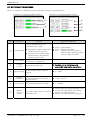
2.7 MOTION SETTING SCREEN
▶ This is a screen for additional function and defrost setting of general devices.
Diagram 2-23. Function Setting Screen
Diagram 2-24. Defrost Setting Screen
1
○
4
○
5
○
6
○
7
○
2
○
3
○
No.
Instruction
Contents
Selects operation mode for
recovering from outage.
1
○
Outage Mode
2
○
Fuzzy Setting
3
○
Locking
Setting
4
○
▶
▶
▶
▶
▶
Recognizes outage, which lasts
longer than three seconds.
If recovers from outage within
three seconds, automatically
restored as HOT state.
Additional Explanation
▶ STOP : Stop operation.
▶ COLD : Operate from WAIT.
▶ HOT : Operate from the position of
▶
SEG that was operating shortly
▶
before outage after WAIT
Settles control during the
occurrence of disturbance
Setting/cancel key lock.
☞ Possible only to shift screen and
☞ execute key input lockup cancellation
Defrost Cycle
It fixes motion cycle of defrost
control.
▶ 0 ~ 9999
5
○
Defrost
Temperature
Input defrost temperature set value
of low temperature room under
defrost control.
▶ -10.0 ~ 100.0℃
6
○
Defrost Time
Fix time starting defrost control.
▶ 1 ~ 99 MIN
7
○
Manual
Defrost
Switch
It is used when defrost control is
manually done.
1st Edition of TEMP880S IM : Sep. 21. 2005
▶
▶
▶
▶
Can be used only during operation stop.
Control low temperature room during
defrost time with defrost SP.
RELAY is on during defrost operation.
Page 33 / 101
SAMWONTECH
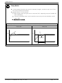
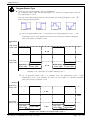
Fuzzy Motion
▶ If load changes intensely and set point frequently changes, overshoot may occur. Fuzzy
▶ can control overshoot effectively.
▶ Internal motion of fuzzy function
1
○
When pointer value (PV) gets close to set point (SP), supporting set point (SUPER SP)
▶
starts calculating.
2
○
Treat this calculated value from the previous step as set point and calculate control
▶ output (MV).
☞ Overshoot is repressed.
▶ Changes of pointer value (PV) according to the function of fuzzy.
Fuzzy OFF
Fuzzy ON
PV
SP
PV
SP
SUPER SP
Fuzzy ON
1st Edition of TEMP880S IM : Sep. 21. 2005
Page 34 / 101
SAMWONTECH
Defrost Control Motion
▶
▶
▶
▶
▶
Defrost control operates when it enters ‘defrost cycle’ which is set up by confirming the
number of repetition of program pattern under operation when a thermal shock tester is
running. If it enters ‘defrost cycle’ segment currently running starts Defrost control in the
initial sector instead of low temperature room. Once Defrost control begins, low
temperature room executes Defrost control with ‘Defrost SP’ already set up.
▶
▶
▶
▶
When Defrost control starts and ‘Defrost time’ goes by, set value of low temperature room
is changed to precooling set value which is set up in the present program pattern, and a
thermal shock tester is converted to ‘under operation preparation(Wait)’ until low
temperature room completes precooling.
▶ Examples
■ Defrost CYCLE = 3 intervals
■ Defrost SP = 20 ℃
■ Defrost Time = 10 min
CYCLE-1 CYCLE-2 CYCLE-3 CYCLE-4 CYCLE-5CYCLE-6 CYCLE-7 CYCLE-8 CYCLE-9
DEFROST CYCLE
DEFROST CYCLE
Diagram-25. Defrost Control Cycle Example
Preheating SP
H.TSP
DEFROST SP
(20℃)
L.TSP
Precooling SP
DEFROST Time
(10 min)
CYCLE-4 Operation
CYCLE-5
CYCLE-6
Under operation
preparation
DEFROST Control
CYCLE-3(DEFROST CYCLE)
Diagram-26. Defrost Control Motion Example
1st Edition of TEMP880S IM : Sep. 21. 2005
Page 35 / 101
SAMWONTECH
2.8 RESERVE SET SCREEN
▶ This is a screen which sets present time and reserve time and operation.
Diagram 2-27. Reserve Set Screen
1
○
2
○
3
○
No.
Instruction
1
○
Present Time
2
○
Reserve Time
3
○
Reserve Set
Contents
Additional Explanation
Sets and displays the present
time(Year, month, day, hour,
minute)
Sets
and
displays
reserve
operation time (Year, month, day,
hour, minute).
Turns on/off reservation.
1st Edition of TEMP880S IM : Sep. 21. 2005
▶ Refer to diagram 2-7
Page 36 / 101
SAMWONTECH
2.9 GRAPPH AND GRAPH RECORD SET SCREEN
▶ This is a screen which displays graphs for the entered pattern at 2.10 PATTERN EDIT
▶ This screen sets graph record (UDC100 : USB saving device)
☞ Graph record function works after UDC100(USB saving device) is purchased.
Diagram 2-28. Graph Indicator Screen
1
○
2
○
3
○
4
○
5
○
6
○
No.
Instruction
Contents
1
○
UDC Button
2
○
Pattern Number
Sets pattern number to graph.
3
○
Graph Indicator
Indicates SP value of laboratory.
Shifts to UDC set screen.
Additional Explanation
▶ UDC Option use
▶ Indicated in blue.
▶ Time scale changes as you
▶ press the button.
4
○
Time Button
5
○
Back/Next
Button
6
○
Time Graph
Changes X axis (time scale) of
graph.
0H
1H
0H
3H
0H
6H
0H
12H
0H
24H
2H
↓
6H
↓
12H
↓
24H
↓
48H
3H
4H
9H
12H
18H
24H
48H
72H
72H
96H
Shifts to back/next stage of X axis
(time scale).
Displays the time progress of the
program operation.
1st Edition of TEMP880S IM : Sep. 21. 2005
▶ Displays red as time progresses.
Page 37 / 101
SAMWONTECH
Diagram 2-29. Graph Record Set Screen
1
○
2
○
3
○
4
○
6
○
5
○
7
○
No.
Instruction
1
○
Motion Mode
2
○
Time Unit
3
○
Record Cycle
4
○
Transmission
Object
Contents
Additional Explanation
▶
▶
▶
▶
“RUN” only during program operation
and fix operation.
Switched to “STOP” when program
operation and fix operation stops.
Selects transmission object.
▶
▶
▶
▶
▶
▶
▶
▶
▶
PTN : Selects parameter for pattern
PTN : set, repetition set, test name
PTN : input.
PARA : Selects all parameters except
PARA : the ones selected at PTN and
PARA : communication related
PARA : parameters.
ALL : Selects all parameters except
ALL : communication related ones.
Upload : Transmits selected object
Upload : from UDC100 to TEMP880S.
Download : Transmits selected object
Download : from TEMP880S to
Download : UDC100.
Activate or stop the graph record
Selects time saving unit.
Sets recording cycle.
5
○
Transmission
Direction
Selects upload/download.
▶
▶
▶
▶
▶
6
○
Transmission
Transmits data
▶ It is impossible to switch screen
▶ during transmission.
7
○
Memory Use
Displays currently using memory.
☞ To use UDC100, format the memory stick to FAT16.
1st Edition of TEMP880S IM : Sep. 21. 2005
Page 38 / 101
SAMWONTECH
2.10 PATTERN SET SCREEN
▶ This is a center of the screen which sets parameter related to program operation.
Diagram 2-30. Pattern Set Screen(Elevator Type)
Diagram 2-31. Pattern Set Screen(Damper Type)
4
○
1
○
2
○
3
○
5
○
10
○
6
○
7
○
8
○
9
○
No.
Instruction
1
○
Pattern Number
Sets pattern number to program.
▶ 120 pattern
2
○
Cycle
Displays the number of repetition
of pattern concerned.
▶ 1 ~ 9999
3
○
Test Name
This button sets up test name.
▶ Can input up to 10 letters.
▶ Refer to 2.10.3 Pattern Name Set.
4
○
Pattern End
Decide operation mode when
pattern ends.
▶ RESET : PT ENDs.
▶ HOLD : Hold at the last SEG.
5
○
Pattern Type
Indication
Indicates program pattern type.
The pattern type is displayed in
▶ As for ELEVATOR TYPE, indicated as
▶ two types, as for DAMPER TYPE,
▶ indicated as four types.
6
○
TSP Set
Sets program pattern target set
point(TSP).
7
○
TIME Set
Sets program pattern operation
time.
8
○
Preheating/Prec
ooling Set
9
○
Time Signal Set
Contents
5 is touched.
order when ○
Sets set point(SP) for preheating
and precooling high, low, and
normal temperature rooms(as for
damper type).
Sets time signal of segment to
operate.
Moves to time signal set screen
Additional Explanation
▶ TSP : RL~RH
▶ RL~RH
▶ Refer to 2.10.2 Time Signal Setting.
10 is touched.
when ○
1st Edition of TEMP880S IM : Sep. 21. 2005
Page 39 / 101
SAMWONTECH
Program Pattern Type
▶ There are four program pattern types in TEMP880S.
▶ As for Elevator Type, there are two types(Type-1,2), and as for Damper Type, there are
▶ four types(Type-1,2,3,4).
5 )’
▶ You can set program pattern type by using ‘Pattern Set Screen((Diagram 2-29)- ○
▶ when setting program pattern.
Type-1
1
○
Type-2
Type-3
Type-4
As for program pattern type-1, it operates from ‘high temperature room → low
▶ temperature room’, and operates as much as the number of inputted repetition
▶ set(Cycle).(Refer to Diagram 2-32)
Temperature
(℃)
High Temp.
Room TSP
Time
Low Temp.
Room TSP
Low Temp.
High Temp.
Room TIME
Room TIME
CYCLE - 1
High Temp.
Room TIME
Low Temp.
Room TIME
CYCLE - n
Diagram 2-32. Operation of Program Pattern Type-1
2
○
As for program pattern type-1, it operates from ‘low temperature room → high
temperature room’, and operates as much as the number of inputted repetition
set(Cycle).(Refer to Diagram 2-33)
Tempera
High Temp.
Room TSP
Time
Low Temp.
Room TSP
Low Temp.
High Temp.
Room TIME
Room TIME
CYCLE - 1
Low Temp.
High Temp.
Room TIME
Room TIME
CYCLE - n
Diagram 2-33. Operation of Program Pattern Type-2
1st Edition of TEMP880S IM : Sep. 21. 2005
Page 40 / 101
SAMWONTECH
3
○
As for program pattern type-1, it operates from ‘normal temperature room → high
temperature room → low temperature room’, and operates as much as the number of
inputted repetition set(Cycle).(refer to Diagram 2-34)
Temperature
(℃)
High Temp.
RoomTSP
Normal Temp.
Room TSP
Time
Low Temp.
Room TSP
Normal
Temp.
Room
TIME
Normal
High
Temp. Temp.
Room Room
TIME
TIME
CYCLE - 1
Low
Temp.
Room
TIME
Normal
Temp.
Room
TIME
Normal
High
Temp. Temp.
Room Room
TIME
TIME
CYCLE - n
Low
Temp.
Room
TIME
Diagram 2-34. Operation of Program Pattern Type-3
4
○
As for program pattern type-1, it operates from ‘normal temperature room → low
temperature room → normal temperature room → high temperature room’ and
operates as much as the number of inputted repetition set(Cycle).(refer to Diagram
2-35)
Temperature
(℃)
High Temp.
Room TSP
Normal Temp.
Room TSP
Time
Low Temp.
Room TSP
Normal
Temp.
Room
TIME
Normal
Low
Temp. Temp.
Room Room
TIME
TIME
CYCLE - 1
High
Temp.
Room
TIME
Normal
Temp.
Room
TIME
Normal
Low
Temp. Temp.
Room Room
TIME
TIME
CYCLE - n
High
Temp.
Room
TIME
Diagram 2-35. Operation of Program Pattern Type-4
1st Edition of TEMP880S IM : Sep. 21. 2005
Page 41 / 101
SAMWONTECH
2.10.1 FILE EDIT SCREEN
Diagram 2-36. File Edit Screen
8
○
1
○
2
○
4
○
5
○
6
○
3
○
7
○
No.
Instruction
1
○
Original Pattern
Sets original pattern number that
you wish to copy.
2
○
Target Pattern
Sets original pattern number that
you target to copy.
3
○
Pattern Delete
Sets original pattern number that
you wish to delete.
4
○
Pattern Copy
Button
5
○
Pattern Delete
Button
6
○
Total Delete
Button
7
○
8
○
Results
Pattern Button
Contents
1 to pattern
Copy pattern set on ○
set ○
2 .
Additional Explanation
▶ Cannot copy without setting point of
▶ the original pattern.
Initialize setting point of pattern
3
which is set in ○
☞ Cannot restore deleted pattern.
Initialize setting point of
all patterns.
Displays copy and delete info.
▶ Message Type
Display
Message
Action
Complete
Explanation
Copy and Delete
Complete
Shifts to diagram 2-30.
※ It is impossible to enter file edit screen under operation.
1st Edition of TEMP880S IM : Sep. 21. 2005
Page 42 / 101
SAMWONTECH
2.10.2 Time Signal Setting Screen
Diagram 2-37. Time Signal Setting – 1screen
1
○
No.
Instruction
1
○
ON Time
2
○
OFF Time
Diagram 2-38. Time Signal Setting – 2screen
2
○
Contents
Additional Explanation
Sets standby time from segment
start point to the point of
occurrence of time signal output.
Sets output stop time of time
signal after time signal appears
according to ON time.
▶ Refer to Diagram2-40. Time Signal
▶ Setting Input Key
▶ Setting NO: 00 → No Time Signal
▶ Setting NO: 01
→ Always output at set segment
▶ Setting NO: 02 ~ 07
▶ → Stops output as much of on time at
▶ set segment, and off time after output
▶ occurs
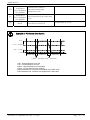
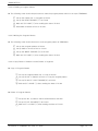
2.10.2.1 How to Set Time Signal
▶ Time Signal 2 of Segment “01” is to set TYPE “1”, Time Signal 3 is toset TYPE “2”,
▶ and Time Signal 4 is to set TYPE “7”.
Diagram 2-39. Befor Setting Time Signal
Diagram 2-40. Time Signal Setting Input Key
7
○
8
○
2
○
9
○
1
○
3
○
4
○
5
○
6
○
1) Diagram2-40. Time Signal Setting Input Key is displayed if you press anywhere of
1
○
on the
previous screen of Diagram2-39. Before Setting Time Signal will be displayed.
2 →○
3 →○
4 →○
7 →○
5
2) Setting the name of pattern which is wanted by pressing Button in order as ○
→○
4 →○
8 →○
6 →○
4 →○
9 of the Diagram 2-40. Time Signal Setting Input Key.
☞ Refer to 2.10.2 Time Signal Setting for input time signal type.
1st Edition of TEMP880S IM : Sep. 21. 2005
Page 43 / 101
SAMWONTECH
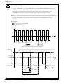
EXAMPLE OF TIME SIGNAL INPUT USE
▶ Program Pattern Setting Point
▶ Time Signal Setting Point
▶ Time Signal Motion in Segment Concerned
Setting
Time Signal Use
OFF TIME
1 ON TIME
○
=00.00
(Time signal
NO :04 Setting
point)
Established ZONE
time
≥ ON TIME
+OFF TIME
☞It does not affect
☞the next SEG.
ON
Time
Signal 1
OFF
ZONE
Normal Temp. Low Temp.
High Temp.
Room(8HOUR) Room(8HOUR) Room(8HOUR)
OFF TIME
2 ON TIME
○
≠00.00
(Time signal
NO :05 Settting
point)
ON TIME
ON
Time
Signal 1
OFF
ZONE
Normal Temp. Low Temp.
High Temp.
Room(8HOUR) Room(8HOUR) Room(8HOUR)
OFF TIME
3 ON TIME
○
=00.00
(Time signal
NO :06 Setting
point)
ON
Time
Signal 2
OFF
ZONE
Established ZONE
TIME
< ON TIME
+OFF TIME
Normal Temp. Low Temp.
High Temp.
Room(8HOUR) Room(8HOUR) Room(8HOUR)
OFF TIME
4 ON TIME
○
≠00.00
(Time signal
NO :07 Setting
point)
ON
Time
Signal 3
OFF
ZONE
1st Edition of TEMP880S IM : Sep. 21. 2005
ON TIME
Normal Temp. Low Temp.
High Temp.
Room(8HOUR) Room(8HOUR) Room(8HOUR)
Page 44 / 101
SAMWONTECH
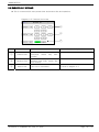
2.10.3 Pattern Name Set
2.10.3.1 Pattern Name Set Method
▶ Setting method to enter pattern name, “TEST 8593W, in Pattern 3.
Diagram 2-41. Before Setting Test Name
Diagram 2-42. Pattern Name Setting Input Key
8
○
3
○
1
○
9
○
4
○
5
○
2 ○
7 ○
6
○
1 on the
3) Diagram2-42. Pattern Name Setting Input Key is displayed if you press anywhere of ○
previous screen of Diagram2-41. Pattern Name Setting will be displayed.
2 →○
8 →○
3 →○
5 →○
3
4) Setting the name of pattern which is wanted by pressing Button in order as ○
→○
3 →○
2 →○
6 →○
2 →○
3 →○
3 →○
3 →○
9 →○
3 →○
3 →○
3 →○
7 →○
3 →○
3 →○
3 →○
8 →○
3 →○
3 →
3 →○
7 →○
4
○
of the Diagram 2-42. Pattern Name Setting Input Key.
1st Edition of TEMP880S IM : Sep. 21. 2005
Page 45 / 101
SAMWONTECH
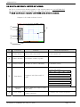
2.11 DISPLAY SET
▶ Screen that adjusts light and activation of auto tuning.
▶ Screen that shows error history.
Diagram 2-43. Display Set
Diagram 2-44. Error Histroy
5
○
1
○
2
○
4
○
3
○
8
○
6
○
9
○
7
○
No.
Instruction
1
○
Tuning
Button
2
○
Power Saving
Time
Contents
Additional Explanation
Activate program preparation
screen, AT button of program
operation screen or hide them.
▶ Displays or hides tuning button in
▶ Diagram2-15, Diagram2-16.
Sets time for back light automatic
turn off.
▶ Initially set 10 minutes for longing the
▶ back light life.
3
○
Light
Increasing
Button
Lightens screen.
4
○
Light
Decreasing
Button
Darkens screen.
▶
▶
▶
▶
5
○
Error History
Button
Shifts to error history screen.
6
○
Error
Occurrence
Order
Displays error occurrence order.
7
○
8
○
9
○
Error
Occurrence
Name
Error
Occurrence
Time
Error History
Delete
Screen light may change as a trait of
STN LCD. For example, it looks darker in
winter and lighter in summer. Adjust
light using this button.
▶ It can display up to five. Error after the
▶ fifth one is stored at the end, and the
▶ first one is deleted.
Displays error occurrence name.
Displays error occurrence time.
Delete all error history.
1st Edition of TEMP880S IM : Sep. 21. 2005
Page 46 / 101
SAMWONTECH
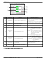
2.12 SYSTEM SETUP SCREEN
▶
▶
▶
▶
☞
☞
Screen for initial setting for operation
As it’s possible to approach without a password in case of forwarding from factory, make sure of
setting a password at 2.12.8 initialization mark and condition mark lamp Setting when it’s not
necessary to block the general user.
When it’s changed in a wrong way, the Setting Points within the System Setting Screen can cause a
problem in operating an equipment.
Diagram 2-45. System Setup Screen
9
○
1
○
5
○
2
○
6
○
3
○
7
○
4
○
8
○
No.
Instruction
1
○
INPUT SET
2
○
Contents
Additional Explanation
Shifts to input and input
compensation setting screen.
▶ Refer to 2.12.1 INPUT AND INPUT
▶ COMPENSATION SETTING
OUTPUT SET
Shifts to control output and
transmission setting screen.
▶ Refer to 2.12.2 Control Output AND
▶ TRANSMISSION SETTING
3
○
INNER SIGNAL
Shifts to inner signal setting
screen.
▶ Refer to 2.12.3 INNER SIGNAL
▶ SETTING
4
○
PID GROUP
Shifts to PID related setting
screen.
▶ Refer to 2.12.4 PID SETTING
5
○
DO CONFIG
Shifts to additional output setting
screen.
▶ Refer to 2.12.5 DO CONFIG
▶ SETTING
6
○
ALARM & DI
Shifts to alarm DI setting screen.
▶ Refer to 2.12.6 ALARM AND DI
▶ ERROR NAME SETTING
7
○
COMM. SET
Shifts to communication related
setting screen.
▶ Refer to 2.12.7 COMMUNICATION
▶ SETTING
8
○
INIT DISPLAY
Shifts to initial screen related and
condition display lamp setting
screen.
▶ Refer to 2.12.8 INITIAL DISPLAY AND
▶ CONDITION DISPLAY LAMP SETTING
Sets whether a thermal shock
tester is DAMPER TYPE or
ELEVATOR TYPE.
▶
▶
▶
▶
☞
▶
9
○
CHAMBER TYPE
1st Edition of TEMP880S IM : Sep. 21. 2005
Control zone in the first SEG during
program operation when it is set to
be ELEVATOR TYPE with TSP
concerned.
Preheating SP and precooling SP
will proceed in other zone.
Page 47 / 101
SAMWONTECH
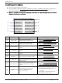
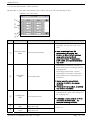
2.12.1 INPUT AND INPUT REVISION FOR SECTIONS
2.12.1.1 INPUT SENSOR SETTING
Diagram 2-46. Input Sensor Setting
Diagram 2-47. SP LIMIT Setting
4
○
1
○
2
○
3
○
8
○
9
○
10
○
11
○
5
○
6
○
7
○
12
○
No.
Instruction
Contents
1
○
SENSOR SET
Choose input sensor.
2
○
TEMP RANGE
Sets temperature range.
3
○
TC SELECT
4
○
SENSOR UNIT
Additional Explanation
Chooses RJC use when sensor
input kind is TC.
▶ You can choose T C, T+R, RJC.
Choose display unit.
▶ ℃,℉
Choose PV motion direction
whenasensor is open.
▶
▶
▶
▶
▶ Refer to 2.12.1.2 SECTION INPUT
▶ REVISION SETTING
5
○
BOUT
6
○
ALL BIAS
Sets revision value for all ranges
on input.
7
○
FILTER TIME
Removes noise when measuring
input includes noise of high
frequency.
8
○
High
Temperature
Room SP
9
○
Normal
Temperature
Room SP
10
○
Low
Temperature
Room SP
11
○
Defrost SP
12
○
HIDDEN
BUTTON
UP : PV moves up toward sensor
UP : input.
DOWN : PV moves down toward
DOWN : sensor input.
Sets upper and lower limits of
TSP,WAIT SP setting range of high
temperature room during program
input.
Sets upper and lower limits of
TSP,WAIT SP setting range of
normal temperature room during
program input.
Sets upper and lower limits of
TSP,WAIT SP setting range of low
temperature room during program
input.
Sets upper and lower limits of
defrost temperature range during
defrost control.
Shifts section input revision
setting.
▶
▶
▶
▶
Displays 2.13 PASSWORD INPUT
screen.
Refer to 2.12.1.2 SECTION INPUT
REVISION SETTING
☞ cannot change sensor kind during operation.
☞ Displays “S.OPN“ when sensor is disconnected. Displays PRESET OUTPUT for Control Output (MV).
1st Edition of TEMP880S IM : Sep. 21. 2005
Page 48 / 101
SAMWONTECH
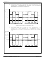
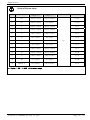
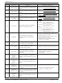
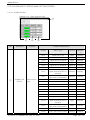
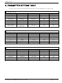
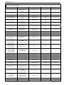
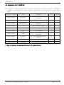
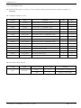
Kinds of Sensor Input
No
SENSOR SET
Temperature
Range (℃)
Temperature
Range (℉)
1
K1
-200.0~1370.0
-300.0~2500.0
TC-K1
2
K2
-200.0~1000.0
0.0~2300.0
TC-K2
3
J
-200.0~1200.0
-300.0~2300.0
TC-J
4
E
-200.0~1000.0
-300.0~1800.0
TC-E
5
T
-200.0~400.0
-300.0~750.0
TC-T
6
R
0.0~1700.0
32~3100
TC-R
7
B
0.0~1800.0
32~3300
8
S
0.0~1700.0
32~3100
TC-S
9
L
-200.0~900.0
-300.0~1600.0
TC-L
10
N
-200.0~1300.0
-300.0~2400.0
TC-N
11
U
-200.0~400.0
-300.0~750.0
TC-U
12
W
0.0~2300.0
32~4200.0
TC-W
13
Platinel Ⅱ
0.0~1390.0
-32.0~2500.0
TC-P
SENSOR GROUP
T/C
DISP
TC-B
☞ Display : -5% ~ +105% of the above range
1st Edition of TEMP880S IM : Sep. 21. 2005
Page 49 / 101
SAMWONTECH
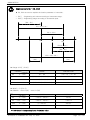
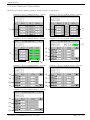
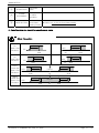
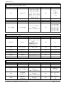
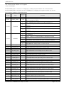
Engineering Units – EU, EUS
▶ EU, EUS are used to explain the interior parameter of controller.
☞ EU( ) : Engineering unit value according to instrument range.
☞ EUS( ) : Engineering range according to instrument span.
| RH - RL |
EU -100~100%
EU 0~100%
RL
0
RH
EUS 0~100%
| RH - RL |
EUS -100~100%
| RL |
| RH |
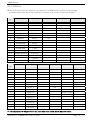
▶ Range of EU( ), EUS( )
RANGE
CENTER POINT
EUS
-100 ~ 100%
RL ~ RH
| RH – RL | / 2 + RL
EUS
-100 ~ 100%
- ( | RH – RL | + | RL | ) ~ RH
RL
EUS
-100 ~ 100%
0 ~ | RH – RL |
| RH – RL | / 2
EUS
-100 ~ 100%
- | RH – RL | ~ | RH – RL |
0
▶ INPUT = T C(TC-T)
▶ RANGE = -200.0℃(RL) ~ 400.0℃(RH)
RANGE
CENTER POINT
EUS
-100 ~ 100%
- 200.0 ~ 400.0℃
100.0℃
EUS
-100 ~ 100%
- 800.0 ~ 400.0℃
- 200.0℃
EUS
-100 ~ 100%
0 ~ 600.0℃
300.0℃
EUS
-100 ~ 100%
- 600.0 ~ 600.0℃
0.0℃
☞ ABS doesn’t change along input of absolute value.
1st Edition of TEMP880S IM : Sep. 21. 2005
Page 50 / 101
SAMWONTECH
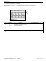
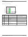
2.12.1.2 SECTION INPUT REVISION SETTING
▶ Section revision is applied as a form of linear equation between each revision points.
Diagram 2-48. Section Input Revision Setting
1
○
2
○
3
○
No.
Instruction
Contents
1
○
DRY TEMP
DIFFERENCE
VALUE
Sets revision temperature at each
standard temperature..
2
○
DRY TEMP
REFERENCE
POINT
Sets each standard temperature.
3
○
BIASED DRY
TEMP PV
Display temperature input revision
is applied.
1st Edition of TEMP880S IM : Sep. 21. 2005
Additional Explanation
Page 51 / 101
SAMWONTECH
Sensor Input Revision Setting
▶
▶
▶
▶
Indicates section input revision at the temperature
S.PV = Actual SensorTemperature, B.PV = Temperature after the revision,
input, RH = Above input
Pn(P) = Standard Temperature, Pn(D) = Revision Temperature
(POINT n.DPV= Pn(P), POINT n.DDV= Pn(D))
(n = 1, 2, 3, 4, 5, 6, 7, 8 )
RL = Below
P8(D)
P6(D)
P7(D)
P5(D)
P4(D)
P3(D)
P2(D)
P1(D)
B.PV
S.PV
RL
P1(P)
P2(P)
P3(P)
P4(P)
P5(P)
P6(P)
P7(P)
P8(P)
RH
▶ B.PV at RL ~ POINT1
= S.PV + P1(D)
▶ B.PV at POINT1 ~ POINT2
( P2(D) – P1(D) )
= S.PV + ( S.PV – P1(P) )
X
+ P1(D)
( P2(P) – P1(P) )
▪
▪
▪
▪
▶ B.PV at POINT7 ~ POINT8
= S.PV + ( S.PV – P7(P) )
X
( P8(D) – P7(D) )
( P8(P) – P7(P) )
+ P7(D)
▶ B.PV at POINT8 ~ RH
= S.PV + P8(D)
1st Edition of TEMP880S IM : Sep. 21. 2005
Page 52 / 101
SAMWONTECH
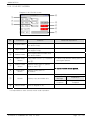
2.12.2 CONTROL OUTPUT AND TRANSMISSION SETTING SCREEN
2.12.2.1 CONTROL OUTPUT SETTING
Diagram 2-49. Control Output Set
1
○
3
○
2
○
4
○
5
○
6
○
No.
Instruction
1
○
OUTPUT TYPE
2
○
DIRECTION
Sets right and reverse motion of
PID control.
CYCLE
Sets output cycle when Control
Output is “ SSR (Solid State
Relay) ”
3
○
Contents
Sets a kind of control output.
PRESET OUT
Cuts PID output from STOP,
S.OPN, ERROR occurring and
displays PRESET OUT
5
○
ANTI RESET
WIND-UP
When control output exceeds
setting point, it prevents WIND-UP
by stopping reset wind-up
operation, and sets point of
resuming PID operation as
deviation range.
6
○
WAIT SP
DEVIATION
Sets deviation value for WAIT SP.
4
○
Additional Explanation
1st Edition of TEMP880S IM : Sep. 21. 2005
▶ Controls senstively if output cycle is
▶ short.
Page 53 / 101
SAMWONTECH
Right and Reverse Motion
Control output(MV)
100 %
Right
Reverse
Control output increase when
PV< SP
Control output increase when
PV> SP.
-
+
0%
Deviation(PV
-SP)
CYCLE TIME
▶ Applies only when a kind of control output is “SSR(Solid State Relay)”
▶ Indicates on/off time of one cycle.
▶ where output cycle is 10 sec.
Control Output: 30%
Control Output: 50%
10 sec
10 sec
Control Output: 70%
10 sec
ON
OFF
ON
OFF
ON
OFF
3 sec
7 sec
5 sec
5 sec
7 sec
3 sec
1st Edition of TEMP880S IM : Sep. 21. 2005
Page 54 / 101
SAMWONTECH
ANTI RESET WIND-UP
▶
▶
▶
▶
One of methods to control during disturbance.
Doesn’t operate when PID Setting Point is I=0.
Control Output(MV) at PID control
MV = P(Proportional value) + I(Integral value) + D(Differential value)
When there is no possibility of ANTI RESET
WIND-UP
PV
SP
MV
DisturbanceOccu
Disturbance Cancellation
When disturbance occurs, Control Output(MV) rises to fit with setting point(SP) and pointing
value(PV) drops.
If such disturbance sustains for a long time, it takes long time for disturbance to be cancelled
due to accumulation of intgral value. Overshoot is large as diagram above and it takes time for
pointing value (PV) to be stablized.
P BAND
PV
SP
MV
DisturbanceOccu
Disturbance Cancellation
From the point where pointing value (PV) enters into P BAND, overshoot is small and PV is
stablized fast because accumulation of the integral value is solved.
▶ Example of how to set P BAND
→ Sensor Input:0.0~100.0℃ , Current Operation PID No. : 1 , P of PID1 group:10.0% ,
→ ARW : 200%
→ P BAND = 200% of P
→ ARW계산 = 20.0%(P*2)
→ ARW계값 = 20.0℃(total input*0.2)
☞ MV starts changing from|PV-SP|= P BAND point
Ex) Setting Point(SP): Control Output(MV) starts changing from PV:50.0℃ if PV is 70.0℃.
→ Since |PV-SP|= P BAND, |50.0 -70.0|=20.0
P
U
D
N
I
W
T
E
S
E
R
I
T
N
A
f
o
y
t
i
l
i
b
i
s
s
o
p
a
s
i
e
r
e
h
t
n
e
h
W
1st Edition of TEMP880S IM : Sep. 21. 2005
Page 55 / 101
SAMWONTECH
2.12.2.2 TRANSMISSION OUPUT SET
Diagram 2-50. Transmission Output Setting
1
○
2
○
1
○
2
○
No.
Instruction
Contents
Additional Explanation
1
○
RET1. SLELCT
Chooses transmission 1 kind.
2
○
RET1. RANGE
Sets the upper and lower limit of
output of transmission 1.
3
○
RET2. SLELCT
Chooses transmission 1 kind.
4
○
RET2. RANGE
Sets the upper and lower limit of
output of transmission 1.
▶ RTP.PV(laboratory PV)
▶ HTP.PV(high temperature room PV)
▶ LTP.PV(low temperature room PV)
▶ RTP.PV(laboratory PV)
▶ HTP.PV(high temperature room PV)
▶ LTP.PV(low temperature room PV)
☞ Transmission output is displayed as 4~20mA. If you want to use transmission output as 1~5V,
☞ Please use it after attaching 250Ω RN-TYPE resistance (precision resistance) at the Transmission
☞ output terminal.
Output Based on Transmission Output Kind
4.0mA
12.0mA
RET RANGE LOW
(RL + RH) / 2
1st Edition of TEMP880S IM : Sep. 21. 2005
20.0mA
RET RANGE HIGH
Page 56 / 101
SAMWONTECH
2.12.3 INNNER SIGNAL SETTING SCREEN
▶ Can set eight inner signals.
Diagram 2-51. Inner Signal Setting Screen
2
○
3
○
1
○
6
○
4
○
5
○
No.
Instruction
Contents
Additional Explanation
1
○
RANGE LOW
Sets minimum value of Inner
Signal.
2
○
RANGE HIGH
Sets maximum value of Inner
Signal.
3
○
DELAY TIME
Sets delay time of Inner Signal.
4
○
TYPE BUTTON
Selects Inner Signal kind to use..
5
○
BAND BUTTON
Selects direction of Inner Signal.
6
○
Screen Move
Button
Sets eight inner signals using UP,
DOWN button.
▶
▶
☞
☞
☞
SP : Present Setting Point
PV : Present pointing value
It has hysteresis of EUS 0.5%
(impossible to change) when selected
to PV.
▶ Switches screen to two Inner Signal
▶ units.
Operating Direction of Inner Signal
RL(℃,%)
RNG.LOW
RNG.HIGH
RH((℃,%)
IS Operating
[ BAND = INB ]
1st Edition of TEMP880S IM : Sep. 21. 2005
RL(℃,%)
RNG.LOW
IS Operating
RNG.HIGH
RH((℃,%)
IS Operating
[ BAND = OUTB ]
Page 57 / 101
SAMWONTECH
Example of Inner Signal Operation
▶ Inner Signal Operation According To Setting Point
Setting
Inner Signal Move
HYS
50.5
▶ INPUT = 0.0 ~ 100.0
→ EUS 0.5% = 0.5
▶
▶
▶
▶
▶
TYPE = PV
RANGE LOW = 30.0℃
RANGE HIGH = 50.0℃
DIRECT = IN BAND
DELAY TIME = 00.00
Normal
Temp.
Room
HighTemp. Normal
LowTemp.
Temp.Room
Room
Room
PV
50.0
INB
30.0
HYS
29.5
IS
ON
OFF
▶ INPUT = 0.0 ~ 100.0
→ EUS 0.5% = 0.5
HYS
49.5
▶
▶
▶
▶
▶
HYS
30.5
TYPE = PV
RANGE LOW = 30.0℃
RANGE HIGH = 50.0℃
DIRECT = OUT BAND
DELAY TIME = 00.00
Normal
Temp.
Room
HighTemp. Normal
LowTemp.
Temp.Room Room
Room
PV
OUTB
50.0
30.0
IS
OUTB
ON
OFF
Normal
Temp.
Room
▶ INPUT = 0.0 ~ 100.0
HighTemp. Normal
Room
Temp.Room LowTemp.
Room
SP
50.0
▶
▶
▶
▶
▶
INB
TYPE = SP
RANGE LOW = 30.0℃
RANGE HIGH = 50.0℃
DIRECT = IN BAND
DELAY TIME = 00.10
30.0
IS
DELAY
TIME
ON
OFF
Normal
Temp.
Room
▶ INPUT = 0.0 ~ 100.0
HighTemp. Normal
Room
Temp.Room LowTemp.
Room
SP
OUTB
50.0
▶
▶
▶
▶
▶
TYPE = SP
RANGE LOW = 30.0℃
RANGE HIGH = 50.0℃
DIRECT = OUT BAND
DELAY TIME = 00.10
30.0
OUTB
ON
IS
OFF
1st Edition of TEMP880S IM : Sep. 21. 2005
DELAY
TIME
Page 58 / 101
SAMWONTECH
2.12.4 PID SET SCREEN
2.12.4.1 PID RANGE SET
▶ Consists of 3 Temperature PIDs and 1 deviation PID.
Diagram 2-52. PID Range Set Screen
7
○
1
○
3
○
8
○
9
○
10
○
11
○
4
○
5
○
12
○
6
○
2
○
No.
Instruction
1
○
2
○
RDV PID
ZONE PID
3
○
TEMP RANGE
HIGH
4
○
REFERENCE
POINT2
5
○
REFERENCE
POINT1
Contents
Deviation PID
Temperature PID group.
High limit of temperature.
Sets limit value which selects
ZONE PID for temperature SPAN.
▶ RL≤RP1≤RP2≤RH
▶
▶
▶
▶
☞
TEMP RANGE
LOW.
Low limit of temperature.
7
○
REFERENCE
HYSTERESIS
Selects ysteresis width when
selecting PID group at Zone PID.
8
○
9
○
▶ Shifts to the setting screen of target
▶ PID group if you press number.
▶
▶
▶
☞
6
○
High
Temperature
Room
REFERENCE
DEVIATION
Low
Temperature
Room
REFERENCE
DEVIATION
Additional Explanation
It changes as TEMP.RH(TEMP RANGE
HIGH) setting point of 2.12.1.1
Temperature Input Setting changes.
Cannot amend.
It changes as TEMP.RL ▶ (TEMP
RANGE LOW) setting point of
2.12.1.1 Temperature Input Setting
changes.
Cannot amend.
Sets deviation value when
choosing high temperature PID.
Sets deviation value when
choosing low temperature PID.
1st Edition of TEMP880S IM : Sep. 21. 2005
Page 59 / 101
SAMWONTECH
10
○
11
○
12
○
High
Temperature
Room RUNNING
PID NUMBER
Low
Temperature
Room RUNNING
PID NUMBER
CONTROL
MODE
Indicates PID number of
currentlyoperating high
temperature room.
Indicates PID number of
currentlyoperating low temperature
room.
Sets D.DV or D.PV as operation
mode when controls PID.
▶ Initial value is “D.PV”.
Example of PID Sector Set Screen
H.SP
H.SP – H.RDV
L.SP – L.RDV
L.SP
ZONE PID
H.RDV
ZONE PID
deviationL.RDV
ZONE PID
deviation
H.SP : High temperature room SP
L.SP : Low temperature room SP
H.RDV : High temperature room deviation
L.RDV : Low temperature room deviation
H.RDV deviation PID : Deviation PID applied with H.RDV value
L.RDV deviation PID : Deviation PID applied with L.RDV value
1st Edition of TEMP880S IM : Sep. 21. 2005
Page 60 / 101
SAMWONTECH
PID GROUP AND CONTROL MODE
ZONE PID(PID1~3)
Explanation
RH
PV
▶
▶
▶
▶
▶
RP2
RHY
RP1
RHY
RL
PID1
PID group is set by pointing value (PV).
Therefore, PID group may change
continuously if pointing value shakes near
RP1 or RP2. To prevent the frequent shake
or PID group, set hysteresis (RHY).
PID3
PID2
Deviation PID(PID4)
Explanation
RH
PV
▶
▶
▶
▶
RDV
SP
RDV
RL
PID4
ZONE
PID
Deviation PID can be used when setting
RDV. Controls deviation PID when pointing
value minus setting point is bigger
deviation setting point (RDV).
PID4
D.DV Control
Explanation
▶
▶
▶
▶
▶
▶
▶
SP
PV
D.PV Control
SP
PV
1st Edition of TEMP880S IM : Sep. 21. 2005
During D.DV control, since changing rate
of output (MV) is small, overshoot is little
and time to target setting point (TSP) is
delayed a little bit.
Suitable for a device which responses
sensitively upon output (MV) changing
rate.
Explanation
▶
▶
▶
▶
▶
▶
During D.DV control, since changing rate
of output (MV) is large, overshoot happens
and time to target setting point (TSP) is
faster than D.DV control time.
Suitable for a device which responses
slowly upon output (MV) changing rate.)
Page 61 / 101
SAMWONTECH
2.12.4.2 PID GROUP(PID1~PID4) SETTING
▶ Generally, it uses value calculated by Auto Tuning, but users can set manually as well.
Diagram 2-53. PID Group
1
○
2
○
3
○
4
○
5
○
No.
Instruction
Contents
Additional Explanation
▶ Lessens the different between setting
▶ point(SP) and the pointing value
▶ (PV).
1
○
PROPORTIONAL
BAND
2
○
INTEGRAL
TIME
3
○
DERIVATIVE
TIME
Sets proportional band.
Sets integral time.
☞
☞
☞
☞
☞
☞
☞
▶
▶
▶
▶
▶
▶
▶
▶
Large proportional band: PV
approaches to SP quickly, but
vibration of MV will affect adversely
upon safety of control Small
proportional band: PV approaches
to SP slowly, and remaining deviation
may occur.
Expanding integral time: Control
Output(MV) is lessened. Therefore,
approaching time to setting point(SP)
is lengthened.
Shortening integral time: Control
Output(MV) is increased. Therefore,
approaching time to setting point is
shortened.
☞
☞
☞
☞
☞
Intergal operation can eliminate
remaining derivitation at program
operation.
If integral time is too short, controlling
may become impossible.
▶ It restraints PV-SP changing rate by
▶ caculating MV which rises along PV▶ SP changing rate.
Sets derivative time.
☞ It restraints a radical change of PV or
☞ disturbance and accerates the ☞
☞ approach to setting point(SP).
4
○
OUTPUT LIMIT
HIGH
Sets control output operation
range limit high.
5
○
OUTPUT LIMIT
LOW
Sets control output
range limit low.
1st Edition of TEMP880S IM : Sep. 21. 2005
operation
▶ OH > OL
Page 62 / 101
SAMWONTECH
2.12.5 DO CONFIG SETTING SCREEN
▶ Setting relay which displays operation signal through I/O relay board.
Diagram 2-54. DO CONFIG Setting – 1screen
2
○
1
○
Diagram 2-56. DO CONFIG Setting – 3screen
Diagram 2-55. DO CONFIG Setting – 2screen
3
○
Diagram 2-57. DO CONFIG Setting – 4screen
7
○
8
○
9
○
4
○
10
○
11
○
5
○
6
○
Diagram 2-58. DO CONFIG Setting – 5screen
12
○
16
○
13
○
17
○
14
○
18
○
15
○
19
○
Diagram 2-59. DO CONFIG Setting – 6screen
Diagram 2-60. DO CONFIG Setting – 7screen
20
○
22
○
21
○
23
○
1st Edition of TEMP880S IM : Sep. 21. 2005
Page 63 / 101
SAMWONTECH
No.
Instruction
Contents
Additional Explanation
1
○
INNER SIGNAL
Sets relay number to display Inner
Signal.
▶ Refer to 2.12.3 Inner Signal Setting
2
○
TIME SIGNAL
Sets relay number to display Time
Signal.
▶ Refer to 2.10.4 Time Signal Setting
3
○
ALARM SIGNAL
Sets relay number to display Alarm
Signal.
▶ Refer to 2.12.6 Alarm and DI ERROR
▶ Name Setting ▶
4
○
DI SIGNAL
Sets relay number to output DI
Signal.
▶ Refer to 2.12.6 DI ERROR Name
▶ Setting
▶ FWD
5
○
DI OUTPUT
Sets output mode of DO(RELAY)
when DI concerned occurs.
-DI
-DI
-DI
-DI
▶ REV
-DI
-DI
-DI
-DI
Sets conversion of operation
condition when DI concerned
occurs.
OFF: ”OFF” contact point of
OFF: DO(RELAY)which is set up
ON : ”ON” contact point of
ON : DO(RELAY)which is set up
▶
▶
▶
▶
☞
▶
OFF:”OFF” contact point of
OFF: DO(RELAY)which is set up
ON :”ON” contact point of
ON : DO(RELAY)which is set up
STOP : Converts RUN => STOP, and
displays DI Error screen.
RUN : Maintains RUN condition, and
displays DI Error screen.
When STOP, RUN simultaneously
occur, STOP > RUN.
6
○
DI MODE
7
○
WAIT DAMPER
OFF
8
○
RUN SIGNAL
Sets relay number to output
Operation (Run) Signal.
▶ Relay is turned on after time you set.
9
○
END SIGNAL
Sets relay number of signal to
output when program operation is
terminated.
▶ Relay is turned on during times set up
▶ when program operation is
▶ terminated.
10
○
11
○
High
Temperature
Room
DAMPER ON
High
Temperature
Room
DAMPER OFF
Determines whether there is output
of DAMPER OFF during WAIT.
Sets relay number of DAMPER ON
signal of high temperature room to
output.
Sets relay number of DAMPER OFF
signal of high temperature room to
output.
Laboratory
DAMPER ON
Sets relay number of DAMPER ON
signal of normal temperature room
to output.
13
○
Laboratory
DAMPER OFF
Sets relay number of DAMPER OFF
signal of normal temperature room
to output.
14
○
Low
Temperature
Room
DAMPER ON
Sets relay number of DAMPER ON
signal of low temperature room to
output.
12
○
1st Edition of TEMP880S IM : Sep. 21. 2005
▶ Used for the exhaustion during
▶ operation of normal sector.
Page 64 / 101
SAMWONTECH
15
○
Low
Temperature
Room DAMPER
OFF
Sets relay number of DAMPER OFF
signal of low temperature room to
output.
16
○
ERROR SIGNAL
Sets relay number to display signal
when error occurs.
17
○
SOLENOID
VALVE SIGNAL
Generates output when PV of low
temperature room is lower than
temperature set up in RUN(WAIT
included).
18
○
1st REF.
SIGNAL
Sets relay number to output signal
for the 1st cooler operation.
19
○
2nd REF.
SIGNAL
Sets relay number to output signal
for the 2nd cooler operation.
20
○
High
Temperature
Room FAN
Sets relay number of FAN value of
high temperature room to output.
21
○
Low
Temperature
Room FAN
Sets relay number of FAN value of
low temperature room to output.
22
○
Laboratory FAN
Sets relay number of FAN value of
laboratory to output.
23
○
N2GAS
▶ Relay is turned on for time you set
▶ when error of D12~D18 occurs.
▶ It is always outputted except for
▶ STOP condition.(DEFROST, WAIT,
▶ HOLD included)
▶ It is outputted during the operation
▶ innormal temperature sector(HOLD,
▶ WAIT included).
Sets relay number of speedy
cooling value to output.
☞ Case where relay numbers are overlapped: If any signal is displayed, relay operates (“OR” condition).
1st Edition of TEMP880S IM : Sep. 21. 2005
Page 65 / 101
SAMWONTECH
2.12.6 ALARM AND DI ERROR NAME SETTING SCREEN
2.12.6.1 ALARM SETTING
Diagram 2-61. Alarm Setting Screen
4
○
1
○
No.
Instruction
2
○
3
○
Contents
Additional Explanation
Display
Alarm Types
Direction
Wait
Operatio
n
AH.F
Upper limit of PV
Right
Nothing
AL.F
Lower limit of PV
Right
Nothing
DH.F
Upper limit of deviation
Right
Nothing
DL.F
Lower limit of deviation
Right
Nothing
DH.R
Upper limit of deviation
Reverse
Nothing
DL.R
Lower limit of deviation
Reverse
Nothing
Reverse
Nothing
Reverse
Nothing
DO.F
DI.F
1
○
ALARM TYPE
SELECT
Selects alarm
type.
AH.R
Upper limit of PV
Reverse
Nothing
AL.R
Lower limit of PV
Reverse
Nothing
AH.FS
Upper limit of PV
Right
Existent
AL.FS
Lower limit of PV
Right
Existent
DH.FS
Upper limit of deviation
Right
Existent
DL.FS
Lower limit of deviation
Right
Existent
DH.FS
Upper limit of deviation
Reverse
Existent
DL.RS
Lower limit of deviation
Reverse
Existent
Right
Existent
Right
Existent
DO.FS
DI.FS
1st Edition of TEMP880S IM : Sep. 21. 2005
Out of the range of
upper and lower limit of
deviation
Within the range of upper
and lower limit deviation
Out of the range of
upper and lower limit of
deviation
Within the range of upper
and lower limit deviation
AH.RS
High Limit Pointing Value
Reverse
Existent
AL.RS
Low Limit Pointing Value
Reverse
Existent
Page 66 / 101
SAMWONTECH
2
○
ALARM POINT
Sets alarm
value.
3
○
ALARM
HYSTERESIS
Sets hysteresis
for alarm
operation.
4
○
NEXT BUTTON
Shifts to DI
Error Name
Setting Screen.
▶ Refer to 2.12.5.2 DI Error Name Setting
☞ Alarm Operation also runs during operation stop status.
Alarm Operation
ON▶
PV
Upper Limit
Deviation
ON▶
HYS
PV
HYS
DEV
- △ ◀OFF
SP
◀ON
▲
ALM
◀OFF
◀ON
PV
Lower Limit
Deviation
Out of
Lower and
Upper Limit
Deviation
Within
Lower and
Upper Limit
Deviation
HYS
PV
▲
ALM
◀ON
▲
ALM
DEV
- △
SP
OFF▶
OFF▶
◀OFF
OFF▶
+
▲
ALM
+
OFF▶
+
◀ON
HYS
◀OFF
▲
ALM
ON▶
HYS
DEV=0
△
SP
ON▶
DEV
-
+
HYS
HYS
DEV
-
▲
ALM
HYS
▲
ALM
1st Edition of TEMP880S IM : Sep. 21. 2005
DEV=0
△
SP
▲
ALM
Page 67 / 101
SAMWONTECH
2.12.6.2 DI ERROR NAME SETTING
Diagram 2-62. DI Error Name Setting Screen
4
○
1
○
2
○
3
○
No.
Instruction
1
○
BUZZER TIME
2
○
Contents
Additional Explanation
Sets time for DI Error buzzer.
▶ Although it is set to“0”, alarm goes
▶ off for at least one minute.
DI1
Using DI1, you can select
operation status (RUN / STOP ).
☞ Cannot amend.
3
○
DI2 ~ DI8
NAME SET
You can set DI error name up to
nine letters (English or number).
▶ Refer to 2.10.6.1 How To Set Pattern
▶ Name for DI name setting.
4
○
NEXT BUTTON
Moves to Alarm Setting Screen.
▶ Refer to 2.12.6.1 Alarm Setting
2.12.6.3 SCREEN DURING DI ERROR OCCURRENCE
Diagram 2-63. Screen During DI Error Occurrence
1
○
2
○
3
○
No.
Instruction
Contents
1
○
EXIT BUTTON
Exits error screen.
2
○
STOP BUTTON
Turns off alarm sound.
3
○
DI ERROR ON
Reverses lamp and name of DI
which has error.
Additional Explanation
▶ Returns to Operation Screen.
☞ Displays error screen again if error is
☞ not resolved.☞
▶ Displays red.
☞ It becomes green after error is
☞ removed.
☞ Operation stops if DI2~DI4 error occurs
☞ It operates by DO CONFIG DI Mode when DI5~DI8 error occurs.
1st Edition of TEMP880S IM : Sep. 21. 2005
Page 68 / 101
SAMWONTECH
2.12.7 COMMUNICATION SET SCREEN
▶ Screen for communication setting.
Diagram 2-64. Communication Set Screen
1
○
2
○
3
○
4
○
6
○
7
○
5
○
No.
Instruction
1
○
PROTOCOL
2
○
BIT PER SEC
3
○
STOP BIT
4
○
PARITY
5
○
DATA LENGTH
6
○
ADDRESS
7
○
RESPONSE
TIME
Contents
Sets communication protocol.
Additional Explanation
▶ Operating Program for the company is
▶ PC LINK1(SUM CHECK)
Sets communication speed.
Sets stop bit.
Sets parity.
Sets data length.
Sets address.
▶ It can be used by connecting and
▶ designating different addresses up to
▶ 99 when communicating via RS485.
Sets response time.
1st Edition of TEMP880S IM : Sep. 21. 2005
Page 69 / 101
SAMWONTECH
2.12.8 INITIAL DISPLAY AND STAUS DISPLAY LAMP SET
2.12.8.1 Initial Display Setting
Diagram 2-65. Initial Display Setting Screen
7
○
8
○
1
○
2
○
3
○
4
○
5
○
6
○
번호
지시내용
내용설명
1
○
RUN TIME
Records total run (operation) time.
부가설명
2
○
PASSWORD SET
Setup password when entering
2.12 System Setting.
▶
▶
▶
▶
▶
☞
▶
The Setting value is “0” when it is
initially delivered from a factory.
Contact where you purchased the
product or the company if you forgot
password.
All data will be initialized to a state of
being delivered from a factory.
3
○
LANGUAGE SET
Selects language (English or
Chinese)
▶ System inner setting screen displays
▶ English regardless of a kind of
▶ language.
4
○
INFORMATION1
You can enter company name up
to 18 letters of number and English
combined.
5
○
INFORMATION2
You can enter company phone
number up to 18 letters of number
and English combined.
6
○
INFORMATION3
You can enter company website
address up to 18 letters of number
and English combined.
7
○
NEXT BUTTON
Moves to Status Display Lamp
Setting Screen.
8
○
CLEAR BUTTON
▶ Refer to 2.12.8.2 Status Display Lamp
▶ Setting
Delete total Operation Time.
1st Edition of TEMP880S IM : Sep. 21. 2005
Page 70 / 101
SAMWONTECH
2.12.8.2 STATUS DISPLAY LAMP SETTING
Diagram 2-66. Status Display Setting Screen
1
○
2
○
3
○
4
○
5
○
6
○
No.
Instruction
Contents
1
○
IS1 ~ IS8
Inner signal displaying lamp.
TS1 ~ TS4
Time signal displaying lamp.
Additional Explanation
2
○
DFR
3
○
AL1 ~ AL4
Defrost operation displaying lamp
Alarm signal displaying lamp.
H.FAN
High temperature room FAN output
displaying lamp
R.FAN
Laboratory FAN output displaying
lamp
L.FAN
Low temperature room FAN output
displaying lamp
N2GAS
Speedy cooling output displaying
lamp
HD ON
High temperature room DAMP ON
displaying lamp
HD OFF
High temperature room DAMP OFF
displaying lamp
RD ON
Laboratory DAMP ON displaying
lamp
RD OFF
Laboratory DAMP OFF displaying
lamp
LD ON
Low temperature room DAMP ON
displaying lamp
LD.OFF
Low temperature room DAMP OFF
displaying lamp
1.REF
Signal displaying lamp for the 1st
cooler operation.
2.REF
Signal displaying lamp for the 2nd
cooler operation.
4
○
5
○
6
○
1st Edition of TEMP880S IM : Sep. 21. 2005
▶ Up to 16 lamps can be selected.
▶ Selected lamp becomes green.
▶ Selected lamp is displayed on fix
▶ operation or the second screen of
▶ program operation.
Page 71 / 101
SAMWONTECH
2.13 PASSWORD INPUT SCREEN
▶ Screen for password input for entering System Setting Screen or Section Input Revision Screen.
Diagram 2-67. Password Input Screen
– System Setting
Diagram 2-68. Password input Screen
– Section Input Revision68
1
○
No.
Instruction
Contents
1
○
INPUT
PASSWORD
Inputs password for entering
System Setting Screen
2
○
INPUT
PASSWORD
Inputs password for entering input
revision screen.
1st Edition of TEMP880S IM : Sep. 21. 2005
2
○
Additional Explanation
▶ initial password is “0”
☞ Switch password at 2.12.8.1 sec
☞ Display Setting.
Page 72 / 101
SAMWONTECH
3. PARAMETER SETTING TABLE
▶ Table that organizes setting range and initial value of inner parameters for each screen.
2.7 Operation Setting
Symbol
Parameter
Setting Range
Unit
Initial Value
POWER MODE
POWER MODE
STOP, COLD, HOT
ABS
STOP
FUZZY SELECT
FUZZY SELECT
OFF, ON
ABS
OFF
KEY LOCK
KEY LOCK
OFF, ON
ABS
OFF
DEFR. CYCLE
DEFROST CYCLE
0(OFF), 1~9999
ABS
0(OFF)
DEFR. SP
DEFROST SP
-10.0~100.0
EU
0.0
DEFR. TIME
DEFROST TIME
DEFROST MANUAL
OPERATION
1~99
ABS
1
OFF, ON
ABS
OFF
DEFR. M.OPER
2.8 Reserve Setting
Symbol
Parameter
Setting Range
Unit
Initial Value
Y
YEAR
0~99
ABS
0, 1
M
MONTH
1~12
ABS
0, 1
D
DAY
1~31
ABS
0, 1
H
HOUR
0~23
ABS
0, 1
M
MINUTE
0~59
ABS
0, 0
RESERVE MODE
RESERVE MODE
OFF, ON
ABS
OFF
2.9 Graph and Graph Record Setting
Symbol
Parameter
Setting Range
Unit
Initial Value
PTNO
PATTERN NUMBER
0~120
ABS
0
RECORD MODE
RECORD MODE
STOP, RUN
ABS
STOP
SAMPLING TIME
SAMPLING TIME
1~59
ABS
5
TIME UNIT
TIME UNIT
SEC, MIN
ABS
SEC
BACKUP ITEM
SELECT BACKUP ITEM
PTN, PARA, ALL
ABS
PTN
DIRECTION
SELECT DIRECTION
DNLOAD, UPLOAD
ABS
DNLOAD
1st Edition of TEMP880S IM : Sep. 21. 2005
Page 73 / 101
SAMWONTECH
2.10 Pattern Setting
Symbol
Parameter
Setting Range
Unit
Initial Value
PTN NO
PATTERN NUMBER
1~120
ABS
1
CYCLE
CYCLE SET
1~9999
ABS
1
END
END MODE SET
RESET(STOP),
HOLD(LAST TSP)
ABS
RESET
PTN NAME 1~120
PATTERN NAME 1~120
0~9, A~Z, Sepcial
Character
(Max. 10 Characters)
ABS
PROG PT001
~ PROG PT120
TSP
SEGMENT(ZONE)
TEMP TSP
EU(0~100%)
EU
EU(0%)
TIME
SEGMENT(ZONE)
TIME
0.01~99.59 (HOUR.MIN)
ABS
00.01
WAIT SP
WAIT SP
EU(0~100%)
EU
EU(0%)
TS1~TS3
TIME SIGNAL1~3
0 ~ 7
ABS
0
SRC. PTNO
SOURCE PATTERN
NUMBER
1~120
ABS
0
DES. PTNO
DESTINATION PATTERN
NUMBER
1~120
ABS
0
DEL. PTNO
DELETE PATTERN
NUMBER
1~120
ABS
0
Symbol
Parameter
Setting Range
Unit
Initial Value
TUNING KEY
TUNING KEY DISPLAY
BUTTON
DISP, HIDE
ABS
DISP
LIGHT OFF
CONTRAST SET
LIGHT OFF
CONTRAST GROUP SET
0~99
8 LEVEL
ABS
ABS
10
4 LEVEL
Symbol
Parameter
Unit
Initial Value
SENSOR
SENSOR SET
ABS
TC-T
UNIT
SENSOR UNIT
Setting Range
TC-K1, TC-K2, TC-J,
TC-J, TC-E, TC-T,
TC-R, TC-B, TC-S,
TC-L, TC-N, TC-U
TC-W, TC-PA
℃, ℉
ABS
℃
EU(0~100%)
TEMP RL < TEMP RH
EU
EU(100%)
EU
EU(0%)
2.11 Screen Selection
2.12.1.1 Input Setting
TEMP RANGE
TEMP RANGE HIGH
TEMP RANGE LOW
TC.SEL
TC SELECT
TC, T+R, RTC
ABS
T+R
B.OUT
BURN OUT
OFF, UP, DOWN
ABS
UP
BIAS
ALL BIAS
EUS(-105~105%)
EUS
EUS(0%)
FILTER
H.TEMP SP
N.TEMP SP
L.TEMP SP
FILTER TIME
0~120 SEC
ABS
0
TEMP SP HIGH
EU(0~100%)
SP.RL < SP.RH
EU
EU(100%)
EU
EU(0%)
EU(0~100%)
SP.RL < SP.RH
EU
100.0
EU
-10.0
DEFROST SP
TEMP SP LOW
DEFROST SP HIGH
DEFROST SP LOW
1st Edition of TEMP880S IM : Sep. 21. 2005
Page 74 / 101
SAMWONTECH
2.12.1.2 Sector Input Revision Setting
Symbol
Parameter
Setting Range
Unit
Initial Value
POINT1.DDV
POINT2.DDV
POINT3.DDV
POINT4.DDV
POINT5.DDV
POINT6.DDV
POINT7.DDV
POINT8.DDV
DIFFERENCE VALUE1~8
EUS(-10~10%)
EUS
EUS(0%)
POINT1.DPV
REFERENCE POINT1
EU(0~100%)
POINT1.DPV
POINT2.DPV
POINT3.DPV
POINT4.DPV
POINT5.DPV
POINT6.DPV
POINT7.DPV
POINT8.DPV ≤RH
EU
EU(0%)
EU
EU(100%)
POINT2.DPV
REFERENCE POINT2
POINT3.DPV
REFERENCE POINT3
POINT4.DPV
REFERENCE POINT4
POINT5.DPV
REFERENCE POINT5
POINT6.DPV
REFERENCE POINT6
POINT7.DPV
REFERENCE POINT7
POINT8.DPV
REFERENCE POINT8
RL≤
≤
≤
≤
≤
≤
≤
≤
2.12.2 Control Output and Transmission Setting
Symbol
Parameter
Setting Range
Unit
Initial Value
TYPE
COMMON OUTPUT
TYPE
SSR, SCR
ABS
SSR
DIRECT
COMMON OUTPUT
DIRECTION
REV, FWD
ABS
REV
CYCLE
COMMON OUTPUT
CYCLE TIME
1~300 SEC
ABS
1
P.OUT
PRESET OUTPUT
-5.0~105.0%
%
0.0%
ARW
ANTI RESET WINDUP
0.0(AUTO), 0.1~200.0
%
100.0
WSP.DEV
WAIT SP DEVIATION
EUS(10%)
EUS
EUS(0.0%)
RET1 SELECT
RET2 SELECT
RETRANSMISSION
SELECT
RTP.PV, HTP.PV,
LTP.PV
ABS
RET1(RTP.PV)
RET2(RTP.PV)
RET1. RANGE
RET2. RANGE
RETRANSMISSION
RANGE HIGH
EU(0~100%)
RET RL < RET RH
EU
EU(100%)
Symbol
Parameter
Setting Range
Unit
Initial Value
RANGE-L
INNER SIGNAL RANGE
LOW
EU
EU(0%)
RANGE-H
INNER SIGNAL RANGE
HIGH
EU
EU(0%)
TIME
INNER SIGNAL DELAY
TIME
00.00~99.59
(HOUR.MIN)
ABS
00.00
TYPE
INNER SIGNAL TYPE
SP, PV
ABS
SP
BAND
INNER SIGNAL BAND
DIRECT
INB, OUTB
ABS
INB
2.12.3 Inner Signal
1st Edition of TEMP880S IM : Sep. 21. 2005
EU(0~100%)
RANGE-L ≤ RANGE-H
Page 75 / 101
SAMWONTECH
2.12.4 PID Setting
Symbol
Parameter
Setting Range
Unit
Initial Value
RP1
REFERENCE POINT1
RP2
REFERENCE POINT2
RL≤RP1≤RP2≤RH
EU
EU(100%)
H.RDV
REFERENCE DEVIATION
EUS(0.0~100.0%)
EUS
EUS(0.0%)
L.RDV
REFERENCE DEVIATION
EUS(0.0~100.0%)
EUS
EUS(0.0%)
RHY
REFERENCE
HYSTERESIS
EUS(0.0~100.0%)
EUS
EUS(0.3%)
H.TEMP PID NO
H.TEMP PID NO
1,2,3,4
ABS
1
L.TEMP PID NO
L.TEMP PID NO
1,2,3,4
ABS
1
CONTROL MODE
CONTROL MODE
D.DV, D.PV
ABS
D.PV
P(1~4)
PROPORTIONAL BAND
0.1~999.9%
ABS
5.0%
I(1~4)
INTEGRAL TIME
0~6000S
ABS
120S
D(1~4)
DERIVATIVE TIME
0~6000S
ABS
30S
OH(1~4)
OUTPUT LIMIT HIGH
100.0
OUTPUT LIMIT LOW
0.0~100.0
OL < OH
ABS
OL(1~4)
ABS
0.0
1st Edition of TEMP880S IM : Sep. 21. 2005
Page 76 / 101
SAMWONTECH
2.12.5 DO CONFIG Setting
Symbol
Parameter
Setting Range
Unit
Initial Value
IS1~IS8 RELAY
INNER SIGNAL1~8
RELAY
0(OFF)~20
ABS
0
TS1~TS3 RELAY
TIME SIGNAL1~3
RELAY
0(OFF)~20
ABS
0
DFR RELAY
DEFROST RELAY
0(OFF)~20
ABS
0
AL1~AL4 RELAY
ALARM SIGNAL1~4
RELAY
0(OFF)~20
ABS
0
DI5~DI8 RELAY
DI SIGNAL5~8
RELAY
0(OFF)~20
ABS
0
DI5~DI8 OUTPUT
DI SIGNAL5~8
OUTPUT TYPE
FWD, REV
ABS
FWD
DI5~DI8 MODE
DI SIGNAL5~8
ERROR MODE
STOP, RUN
ABS
STOP
RUN RELAY
RUN RELAY
0(OFF)~20
ABS
0
RUN CPARA
END RELAY
END CPARA
RUN DELAY TIME
END SIGNAL RELAY
END SIGNAL TIME
0~999 SEC
0(OFF)~20
0~999 SEC
ABS
ABS
ABS
0
0
0
HD.ON RELAY
RD.ON RELAY
LD.ON RELAY
ZONE DAMPER ON
SIGNAL RELAY
0(OFF)~20
ABS
0
HD.ON CPARA
RD.ON CPARA
LD.ON CPARA
ZONE DAMPER ON
SIGNAL TIME
0~999 SEC
ABS
0
HD.OFF RELAY
RD.OFF RELAY
LD.OFF RELAY
ZONE DAMPER OFF
SIGNAL RELAY
0(OFF)~20
ABS
0
HD.OFF CPARA
RD.OFF CPARA
LD.OFF CPARA
ZONE DAMPER OFF
SIGNAL TIME
0~999 SEC
ABS
0
ERROR RELAY
ERROR CPARA
SOL RELAY
SOL CPARA
ERROR RELAY
ERROR SIGNAL TIME
SOL RELAY
SOL SIGNAL TIME
0(OFF)~20
0~999 MIN
0(OFF)~20
EU(0~100%)
ABS
ABS
ABS
EU
0
0
0
EU(0%)
1REF RELAY
FIRST REFRIGERATION
SIGNAL RELAY
0(OFF)~20
ABS
0
1REF CPARA
FIRST REFRIGERATION
SIGNAL TIME
0~999 SEC
ABS
0
2REF RELAY
SECOND
REFRIGERATION
SIGNAL RELAY
0(OFF)~20
ABS
0
2REF CPARA
SECOND
REFRIGERATION
SIGNAL TIME
0~999 MIN
ABS
0
H.FAN RELAY
R.FAN RELAY
L.FAN RELAY
HIGH FAN RELAY
ROOM FAN RELAY
LOW FAN RELAY
0(OFF)~20
ABS
0
N2GAS RELAY
N2GAS CPARA
N2GAS SIGNAL RELAY
N2GAS SIGNAL CPARA
0(OFF)~20
0~999 SEC
ABS
ABS
0
0
1st Edition of TEMP880S IM : Sep. 21. 2005
Page 77 / 101
SAMWONTECH
2.12.6 Alarm and DI Error Name Setting
Symbol
TYPE
ALARM TYPE
POINT
ALARM POINT
Setting Range
AH.F, AL.F, DH.F
DL.F, DH.R, DL.R
DO.F, DI.F, AH.R
AL.R, AH.FS, AL.FS
DH.FS, DL.FS, DH.FS
DL.RS, DO.FS, DI.FS
AH.RS, AL.RS
EU(-105~105%)
HYS
BUZZER TIME
ALARM HYSTERESIS
BUZZER TIME
EUS(0~100%)
0~99 MIN
DI2~DI8 NAME
Parameter
DI2~DI8 NAME
Unit
Initial Value
ABS
ALARM1,3
→ AH.F
ALARM2,4
→ AL.F
EU
EU(100%)
EUS
ABS
EUS(0.5%)
1
DI2:ERR
DI3:ERR
DI4:ERR
DI5:OVR
DI6:OVR
DI7:OVR
DI8:OVR
HTEMP
NTEMP
LTEMP
1.REF
2.REF
1.MOT
2.MOT
0~9, A~Z, Special
Character
(Max. 9 Characters)
ABS
Setting Range
Unit
Initial Value
ABS
PCL1
2.12.7 Communication Setting
Symbol
Parameter
PCL0(PC LINK)
PCL1(PC LINK with SUM
CHECK)
PROTOCOL
PROTOCOL
BPS
BIT PER SEC
600, 1200, 2400,
4800, 9600
ABS
9600
STOP BIT
STOP BIT
1, 2
ABS
1
PARITY
PARITY
NONE, EVEN, ODD
ABS
NONE
D.LENGTH
DATA LENGTH
7, 8
ABS
8
ADDRESS
ADDRESS
1 ~99
(however,Max.99 Sets)
ABS
1
RESPONSE
RESPONSE TIME
0~10
ABS
0
MODA(MODBUS ASCII),
MODR(MODBUS RTU),
SYNM(SYNC MASTER)
2.12.8 Initial Display Setting
Symbol
Parameter
Setting Range
Unit
Initial Value
PASSWORD
LANGUAGE SET
PASSWORD SET
LANGUAGE SET
ABS
ABS
0
ENG
INFO1
COMPANY INFORMATION
ABS
SAMWONTECH
CO.,LTD
INFO2
TELEPHONE
INFORMATION
ABS
TEL: 82-32-3269120
INFO3
HOMEPAGE
INFORMATION
0~9999
ENG, CHN
0~9, A~Z, Special
Character
(Max. 9 Characters)
0~9, A~Z, Special
Character
(Max. 9 Characters)
0~9, A~Z, Special
Character
(Max. 9 Characters)
ABS
WWW.SAMWONTECH.
COM
1st Edition of TEMP880S IM : Sep. 21. 2005
Page 78 / 101
SAMWONTECH
4. Communication Manual
4.1 Communication Specification
▶
▶
▶
▶
TEMP880S adopts the Half-Duplex type of Communication Interface (RS232C or RS485).
In case the Communication Option is RS232C, it is possible to communicate by one to one with a
superior rank of communication equipment such as PC. Especially the model of RS485 , it can be used
by connecting to a superior rank of communication equipment up to the number of 99.
▶ TEMP880S uses the following parameter during the communication.
PARAMETER
Setting Value
Contents
PCL0
Basic Protocol
PCL1
Basic Protocol + Check Sum
MODA
MODBUS ASCII
MODR
MODBUS RTU
SYNM
SYNC MASTER
9600
9600 bps
4800
4800 bps
2400
2400 bps
1200
1200 bps
600
1600 bps
NONE
None Parity
EVEN
Even Parity
ODD
Odd Parity
1
1 bit
2
2 bits
8
8 bits
7
7 bits
ADDRESS
1~99
Address
RESPONSE
0~10
RESPONDING TIME
(=PROCESSING TIME+RESPONSE*10msec)
PROTOCOL
Communication Speed(BPS)
PARITY
STOP BIT
DATA LENGTH
■ Communication related parameter basic value when forwarding from factory
• PROTOCOL
: PCL1(PC LINK+ Check Sum)
• BPS
: 9600 bps
• PARITY
: NONE
• STOP BIT
: 1 (1 bit)
• DATA LENGTH
: 8 (8 bits)
• ADDRESS
:1
• RESPONSE
: 0 (dealing time + 10 msec)
1st Edition of TEMP880S IM : Sep. 21. 2005
Page 79 / 101
SAMWONTECH
4.2 Communication Wiring
▶ Wiring between the TEMP880S and superior rank of communication equipment is different by the
▶ option(RS232C/RS485) of TEMP880 and the contents are as below.
4.2.1 Connecting the TEMP880S 9 Pin connector of RS232C Communication
Master Station
TEMP880S
RD
2
2
RxD
TD
3
3
TxD
RTS
7
CTS
8
SG
5
5
SG
SHIELD
D-Sub 9Pin Female
4.2.2 Connecting the terminal plate of TEMP880S of RS485 Communication
Master Station
TEMP880S
TEMP880S
RTX+
RTX+
RTX+
RTX-
RTX-
RTX-
SG
SG
SG
Vertical
Vertical
i t
SHIELD
Class 3 Ground
Terminal
Class 3 Ground
Terminal
☞ MULTIDROP is possible up to the number of 99 in case of SLAVE(TEMP880).
☞ Make sure to connect the vertical section resistance (200Ω 1/4W) in case of the TEMP880S or
☞ MASTER(PC, PLC etc.)
1st Edition of TEMP880S IM : Sep. 21. 2005
Page 80 / 101
SAMWONTECH
4.3 Communication Command
4.3.1 Composition of Communication Command
▶ The basic style of Communication Command which transmits a message to TEMP880S from a superior
▶ rank of Communication equipment.
☞ MULTIDROP is possible up to the number of 99 in case of SLAVE(TEMP880S).
☞ Make sure to connect the vertical section resistance (200Ω 1/4W) in case of the TEMP880S or
☞ MASTER(PC, PLC etc.)
2
○
3
○
4
○
5
○
,
Date followed by the rule
of COMMAND
6
○
S
T
ADDRESS
COMMAND
X
1
○
7
○
8
○
C
L
R
F
SUM
Beginning letter of Communication Command
Indicate the beginning of Communication Command having a code value (0x02) with a STX (Start of
Text), which is a letter of Ascii.
2
○
ADDRESS
Indicate the ADDRESS which is a number of TEMP880S that you intend to communicate with.
3
○
COMMAND
COMMAND for Communication (refer to 4.3.2~4.3.9).
4
○
Divider
Indicate the Divider which separates the Command and Data by comma (',').
5
○
Data part
Indicate the letter line which has a regular form of a letter line followed the Communication Command
Rule
6
○
Check Sum
Indicate the inferior rank of 2-byte to D by adding all letters from the letter of after STX to the letter
before SUM using the Ascii code and Use only when the protocol of TEMP880S is “the basic protocol of
“PCL!” + Check Sum”
7 , ○
8
○
Vertical Section letter
Indicate the end of Communication Command as CR(0x0D), LF(0x0A) by using the Ascii code.
1st Edition of TEMP880S IM : Sep. 21. 2005
Page 81 / 101
SAMWONTECH
4.3.2 Communication Command Type
▶ The Communication Command of TEMP880Shas a Self Information Command which reads the
▶ information of Communication Command and a Read/Write Command which reads all the information of
▶ TEMP880S.
1
○
Self Information Command
COMMAND
Contents
AMI
2
○
Indicate the model name & version of TEMP880S
Read/Write Command
COMMAND
Contents
RSD
Series Read of D-Register
RRD
Random Read of D-Register
WSD
Series Write of D-Register
WRD
Random Write of D-Register
STD
Random Registration of D-Register
CLD
Call of D-Register which is registered at STD
☞ Each Command can read or write D-Register up to the number of 32. And it should be re-registered
☞ after the power is on in case of STD/CLD when its power source’s off because the registered contents
☞ are initialized.
4.3.3 Error Response
▶ TEMP880S transmits a message as below in case of Error during a Communication.
The number of Byte
1
2
2
2
2
Address
NG
Two
numbers
SUM
S
Contents
T
X
1
1
C
L
R
F
☞ SUM is only used in case the PROTOCOL is “PCL1”.
1st Edition of TEMP880S IM : Sep. 21. 2005
Page 82 / 101
SAMWONTECH
4.3.4 RSD Command
▶ RSD Command is used for reading a series of Data on D-Register.
▶ Format of Transmission
The number
1
of Byte
2
3
1
2
1
4
2
S
Contents
T
Addr
RSD
,
Number
,
D-Reg. No.
1
1
C
L
R
F
SUM
X
▶ Response
The number
of Byte
1
2
3
1
2
1
4
1
4
1
…
Addr
RSD
,
OK
,
dddd-1
,
dddd-2
,
…
2
1
1
C
L
R
F
S
Contents
T
X
1
,
4
dddd-(n-1)
1
,
4
dddd-(n)
SUM
- The Number of : 1~32
- dddd F : Data without a point of 16 number (D)
ex) In case of reading a D-Register from Temperature PV(D0001) to SP(D0002)
- Transmission
: [stx]01RSD,02,0001[cr][lf]
- Transmission (including Check Sum)
: [stx]01RSD,02,0001C5[cr][lf]
([stx] = 0x02, [cr] = 0x0d, [lf] = 0x0a)
In case the received value of each PV, SP is 50.0 and 30.0, will be received as below ;
- Reception
: [stx]01RSD,OK,01F4,012C[cr][lf]
- Reception (including Check Sum ) : [stx]01RSD,OK,01F4,012C19[cr][lf]
※ The process of transforming the PV value of received 16 number data to display on screen.
1
○
2
○
Transformation to decimal number : 01F4(16 number-D-) → 500(decimal number)
Multiply 0.1 to the transformed value. : 500 * 0.1 → 50.0
1st Edition of TEMP880S IM : Sep. 21. 2005
Page 83 / 101
SAMWONTECH
4.3.5 RRD Command
▶ RRD Command is used in case of reading the Random Data on D-Register.
▶Format of Transmission
The number
1
2
of Byte
3
1
2
1
4
1
4
1
…
RRD
,
Numbe
r
,
D-Reg. No1
,
D-Reg. No2
,
…
S
Contents
T
Addr
X
1
4
,
▶ Response
The number
of Byte
1
1
D-Reg. No(n-1)
4
,
2
D-Reg. No(n)
1
1
C
L
R
F
SUM
2
3
1
2
1
4
1
4
1
…
Addr
RRD
,
OK
,
dddd-1
,
dddd-2
,
…
S
Contents
T
X
1
,
4
dddd-(n-1)
1
,
4
dddd-n
2
1
1
C
L
R
F
SUM
- The number of (~) : 1~32
- dddd F : Data without a point of decimal number (16 number D)
ex) In case of reading the D-Register of PV(D0001), SP(D0002)
- Transmission
: [stx]01RRD,02,0001,0002[cr][lf]
- Transmission (Including Check Sum ) : [stx]01RRD,02,0001,0002B2[cr][lf]
In case the value of D0001 is 50.0 and the value of D0002 is 30.0
- Reception
: [stx]01RRD,OK,01F4,012C[cr][lf]
- Reception (including Check Sum) : [stx]01RRD,OK,01F4,012C18[cr][lf]
1st Edition of TEMP880S IM : Sep. 21. 2005
Page 84 / 101
SAMWONTECH
4.3.6 WSD Command
▶ WSD Command is used in case or using the series data of D-Register.
▶ Format of Reception
The number
1
of Byte
2
3
1
2
1
4
1
4
1
…
Addr
WSD
,
Number
,
D-Reg. No1
,
dddd-1
,
…
S
Contents
T
X
1
4
,
▶ Response
The number
of Byte
1
1
dddd-(n-1)
4
,
2
dddd-(n)
T
2
3
1
2
2
Addr
WSD
,
OK
SUM
X
1
C
L
R
F
SUM
S
Contents
1
1
1
C
L
R
F
- The number of (~) : 1~32
- dddd F : Data without a point of decimal number (16 number D)
ex) In case of using defrost SP(D0100) and defrost time(D0111)
- Reception
: [stx]0101WSD,02,0110,0001,0002[cr][lf]
- Reception (including Check Sum) : [stx] 01WSD,02,0110,0001,0002A6[cr][lf]
1st Edition of TEMP880S IM : Sep. 21. 2005
Page 85 / 101
SAMWONTECH
4.3.7 WRD Command
▶ WRD Command is used for using the Random data of D-Register.
▶ Format of Transmission
The number
1
2
of Byte
3
1
2
1
4
1
4
1
…
WRD
,
Number
,
D-Reg. No1
,
dddd-1
,
…
S
Contents
Addr
T
X
1
4
,
▶ Response
The number
of Byte
1
1
D-Reg. No(n)
4
,
2
dddd-(n)
2
3
1
2
2
Addr
WRD
,
OK
SUM
S
Contents
T
X
1
1
C
L
R
F
SUM
1
1
C
L
R
F
- The number of (~) : 1~32
- dddd F : Data without a point of decimal number (16 number D)
ex) In case of using data to Outage Mode(D0105) and Outage Time(D0125)
- Transmission
: [stx] 01RRD,02,0001,0002[cr][lf]
- Transmission (Including Check Sum) : [stx]01WRD,02,0105,0001,0125,00039E[cr][lf]
1st Edition of TEMP880S IM : Sep. 21. 2005
Page 86 / 101
SAMWONTECH
4.3.8 STD Command
▶ STD Command is used for registering preferable D-Register to TEMP880S in advance.
▶ Format of Transmission
The number
1
2
of Byte
3
1
2
1
4
1
4
1
…
STD
,
Numb
er
,
D-Reg. No1
,
D-Reg. No2
,
…
2
1
1
C
L
R
F
S
Contents
Addr
T
X
1
,
▶ Response
The number
of Byte
1
4
1
D-Reg. No(n-1)
4
,
D-Reg. No(n)
2
3
1
2
2
Addr
STD
,
OK
SUM
S
Contents
T
X
SUM
1
1
C
L
R
F
- Number : 1~32
ex) In case of registering PV(D0001), laboratory temperature SP(D0002)
- Transmission
: [stx]01STD,02,0001,0002[cr][lf]
- Transmission(including Check Sum) : [stx]01STD,02,0001,0002B5[cr][lf]
1st Edition of TEMP880S IM : Sep. 21. 2005
Page 87 / 101
SAMWONTECH
4.3.9 CLD Command
▶ CLD Command is used for reading & bring the D-Register which is already registered at TEMP880S by
▶ STD Command.
▶ Formate of Transmission
The number
1
of Byte
2
3
2
Addr
CLD
SUM
S
Contents
T
X
▶ Response
The number
of Byte
1
1
1
C
L
R
F
2
3
1
2
1
4
1
4
1
…
Addr
CLD
,
OK
,
dddd-1
,
dddd-2
,
…
2
1
1
C
L
R
F
S
Contents
T
X
1
,
- Number
- dddd
4
dddd-(n-1)
1
,
4
dddd-(n)
SUM
: 1~32
: Data without a point of 16 number
1st Edition of TEMP880S IM : Sep. 21. 2005
Page 88 / 101
SAMWONTECH
4.4 Explanation of D-REGISTER
▶ D-Register is a group of gathering all the data which is provided to check all the condition of TEMP880S.
▶ D-Register is grouped by each 100 unit, basically, depending on the contents and the contents are as
below.
Scope of D-Register
Group
Contents
Read
Write
D0001~D0099
PROCESS
Indication of a basic driving-related
information
○
X
D0100~D0199
FUNCTION
Set up the driving-related Information
○
△
D0200~D0299
RESERVATION
Set up the time and reservation
functions
○
△
D0300~D0399
IS
Set up the inner-signal
○
○
D0400~D0499
ALARM
Set up the Alarming and Time Signal
○
○
D0500~D0599
PID
P.I.D Setting
○
○
D0700~D0799
COMM
Indication of communication-related
information
○
X
D0800~D0899
OUTPUT
Set up the Control printing & DO
printing
○
○
D0900~D0999
INPUT
Set up of input
○
○
D1000~D1099
PROGRAM
Set up the pattern of Program
○
○
☞ Each of D-Register is composed of 4 places of 16 number (2-Byte).
1st Edition of TEMP880S IM : Sep. 21. 2005
Page 89 / 101
SAMWONTECH
4.4.1 PROCESS
▶ PROCESS group has basic data from the operation of TEMP880S Among these, here’s Bit Map
Information which indicates all the conditions by the unit of Bit and the contents are as below.
NOWSTS
OTHERSTS
ISSTS
TSSTS
ALSTS
(D0010)
(D0011)
(D0012)
(D0013)
(D0014)
0
RESET
DFR
IS1
TS1
AL1
1
RUN
RUN
IS2
TS2
AL2
2
HOLD
END
IS3
TS3
AL3
HD.ON
IS4
HD.OFF
IS5
RD.ON
IS6
bit
3
4
AT
5
6
DEFROST
RD.OFF
IS7
7
ERROR
LD.ON
IS8
8
H.TEMP RUN
LD.OFF
9
N.TEMP RUN
SOL.V
10
L.TEMP RUN
1.REF
11
HIGH DEFROST
2.REF
12
NORMAL DEFROST
HIGH FAN
13
ROOM FAN
14
LOW FAN
15
N2GAS
AL4
SYSERR
DOSTSL
DOSTSH
DIDATA
ERROR
ERROR
(D0015)
(D0016)
(D0017)
(D0018)
(D0019)
(D0020)
0
RELAY 1
RELAY 17
DI1
H.TEMP +OVER R.TEMP +OVER
1
RELAY 2
RELAY 18
DI2
H.TEMP –OVER R.TEMP –OVER
RELAY 3
RELAY 19
DI3
H.TEMP BOUT
3
RELAY
4
RELAY 20
DI4
4
RELAY
5
DI5
5
RELAY
6
DI6
6
RELAY
7
DI7
7
RELAY
8
DI8
8
RELAY 9
L.TEMP +OVER
9
RELAY 10
L.TEMP –OVER
10
RELAY 11
L.TEMP BOUT
11
RELAY 12
12
RELAY 13
13
RELAY 14
14
RELAY 15
15
RELAY 16
bit
2
SYS ERR
R.TEMP BOUT
☞ It’s composed of D-Register which has a real data value except the Bit Map information.
1st Edition of TEMP880S IM : Sep. 21. 2005
Page 90 / 101
SAMWONTECH
▶ Common Driving-related D-Register
D-Reg.
Signs
Contents
D0001
RTEMP_NPV
Laboratory temperature PV
D0002
RTEMP_NSP
Laboratory temperature SP
D0003
HTEMP_NPV
High temperature room temperature PV
D0004
LTEMP_NPV
Low temperature room temperature PV
D0005
LTEMP_PIDNO
Low temperature room PID number
D0006
ROOM_MVOUT
Laboratory control output value
D0007
HIGH_MVOUT
High temperature room control output value
D0008
LOW_MVOUT
Low temperature room control output value
D0009
HTEMP_PIDNO
High temperature room PID number
▶ PROGRAM Driving-related D-Register
D-Reg.
Signs
D0021
PROC_TIME_H
Operation time(hour)
D0022
PROC_TIME_M
Operation time(min)
D0023
RUN_CYCLE
D0024
TOTAL_CYCLE
D0025
SET_SEGMENT_H
Present segment setting time(hour)
D0026
SET_SEGMENT_M
Present segment setting time(min)
D0027
RUN_SEGMENT_H
Repeating frequency of a Segment which is on the process
D0028
RUN_SEGMENT_M
Repeating frequency of a Segment which is set up
D0031
REMAIN_SEGMENT_H
Remained time(hour) of Segment which is driving now
D0032
REMAIN_SEGMENT_M
Remained time(min) of Segment which is driving now
D0033
HTEMP_TSP
Temperature TSP(Target Set Point) of high
temperature room
D0034
NTEMP_TSP
Temperature TSP(Target Set Point) of laboratory
D0035
LTEMP_TSP
Temperature TSP(Target Set Point) of low temperature room
1st Edition of TEMP880S IM : Sep. 21. 2005
Contents
Present repeating frequency
Total repeating frequency which is set up
Page 91 / 101
SAMWONTECH
4.4.2 FUNCTION
▶ FUNCTION Group is consist with a D-Register which is related to the motions of TEMP880S.
▶ D-Register related to PROGRAM Driving
D-Reg.
Signs
Contents
D0100
SET_PTNO
D0109
DEFROST_CYCLE
D0110
DEFROST_SP
D0111
DEFROST_TIME
D0112
DEFROST
Set up the No. of a pattern which is for driving a Program
Set up defrost cycle
Set up defrost temperature
Set up defrost time
Set up whether to use manual defrost ( 0 : OFF, 1 : ON )
▶ D-Register related to Motions
D-Reg.
D0101
D0105
Signs
MODE
PWRMODE
Driving Contents
Setting Value
Contents
RUN
1
PROG RUN
HOLD
2
HOLD ON/OFF
STEP
3
SEGMENT STEP
STOP
4
PROG STOP
STOP
0
Set up the STOP MODE
COLD
1
Set up the COLD MODE
HOT
2
Set up the HOT MODE
1st Edition of TEMP880S IM : Sep. 21. 2005
Page 92 / 101
SAMWONTECH
4.4.3 RESERVATION
▶ RESERVATION group is consist of Time checking, Setting and Reservation-related D-Register of
▶ TEMP880S.
▶ D-Register related to Time
D-Reg.
Signs
D0201
N_YEAR
D0202
N_MONTH
D0203
Contents
Read
Write
Present time of TEMP880S (year)
○
×
Present time of TEMP880S (month)
○
×
N_DAY
Present time of TEMP880S (day)
○
×
D0204
N_HOUR
Present time of TEMP880S (hour)
○
×
D0205
N_MIN
Present time of TEMP880S (min)
○
×
D0206
RUN_YEAR
Reservation time of TEMP880S (year)
○
○
D0207
RUN_MONTH
Reservation time of TEMP880S (month)
○
○
D0208
RUN_DAY
Reservation time of TEMP880S (day)
○
○
D0209
RUN_HOUR
Reservation time of TEMP880S (hour)
○
○
D0210
RUN_MIN
Reservation time of TEMP880S (min)
○
○
D0211
SET_YEAR
Set up the time (year)
×
○
D0212
SET_MONTH
Set up the time (month)
×
○
D0213
SET_DAY
Set up the time (day)
×
○
D0214
SET_HOUR
Set up the time (hour)
×
○
D0215
SET_MIN
Set up the time (min)
×
○
▶ Reservation Work ON/OFF
D-Reg.
Signs
D200
RESERVE
Driving contents
Setting Value
Contents
OFF
0
Cancellation of reservation
ON
1
Setting of reservation
1st Edition of TEMP880S IM : Sep. 21. 2005
Page 93 / 101
SAMWONTECH
4.4.4 Set up the Pattern of Program
4.4.4.1 PROGRAM
▶ PROGRAM group is consist of D-Register for making Program Pattern with Communication.
▶ PROGRAM pattern should be set up at TEMP880S by changing the segment number one by one.
▶ D-Register related to PROGRAM Pattern
D-Reg.
Signs
Setting
Value
D1000
P_PTNO
1~120
Set up the No. of Program Pattern when reading or writing
D1001
DEST_PTNO
1~120
Set up the No. of Program Pattern which will be copied
when copying the Pattern
1
2
D1003
TRIGGER
3
4
D1004
ANSWER
Contents
INIT : Initializing the contents of D1000~D1004 to '0'
READ : Reading with the contents which is set up at D1000
& D1002
WRITE : Writing with the contents which is set up at D1000
& D1002
PT COPY : Copying the pattern set up at D1000 to the pattern
of D1001
5
PT DEL : Deleting the pattern which is set up at D1000
0
FULL : Exceeding of the limited number of pattern or segment
at TEMP880S
1
DONE : Order of D1003(TRIGGER) is managed normally
2
PT EMPTY : No contents set up at a pertinent pattern
4
SEG EMPTY : Not contents set up at a pertinent segment
5
PT RUN : TEMP880S is in PROG RUN condition
6
PARA ERROR : Setting Error of D1000~D1003
D1010
HTEMP_TSP
-
PT USED : a pertinent pattern is the condition of PROG RUN
D1011
NTEMP_TSP
-
Normal temperature room TSP to read or write
D1012
LTEMP_TSP
-
Low temperature room TSP to read or write
D1013
HTEMP_TIME
-
High temperature room setting time to read or write
D1014
NTEMP_TIME
-
Normal temperature room to read or write
D1015
LTEMP_TIME
-
Low temperature room to read or write
D1016
HTEMP_WSP
-
High temperature room preheating SP to read or write
D1018
LTEMP_WSP
-
Low temperature room precooling SP to read or write
D1019
HTEMP_TS1
-
High temperature room time signal 1 to read or write
D1020
HTEMP_TS2
-
High temperature room time signal 2 to read or write
D1021
HTEMP_TS3
-
High temperature room time signal 3 to read or write
D1022
NTEMP_TS1
-
Normal temperature room time signal 1 to read or write
D1023
NTEMP_TS2
-
Normal temperature room time signal 2 to read or write
D1024
NTEMP_TS3
-
Normal temperature room time signal 3 to read or write
D1025
LTEMP_TS1
-
Low temperature room time signal 1 to read or write
D1026
LTEMP_TS2
-
Low temperature room time signal 2 to read or write
D1027
LTEMP_TS3
-
Low temperature room time signal 3 to read or write
D1030
PATTERN_TYPE
-
Program pattern type to read or write
D1031
CYCLE
-
Program pattern repetition frequency to read or write
D1032
END_MODE
-
Operation mode when closing program pattern to read or write
1st Edition of TEMP880S IM : Sep. 21. 2005
Page 94 / 101
SAMWONTECH
4.4.4.2 Reading a Program Pattern
▶ The following order should be performed to read the program pattern which is set up at TEMP880S.
1
○
2
○
3
○
4
○
Set up the Pattern No. of Program at D1000
Set up the READ TRIGGER (‘2’) at D1003
Wait until it’s DONE(‘1’) after reading the data of D1004
Read data recorded at D1010~D1032.
4.4.4.3 Writing the Program Pattern
▶ The following order should be done to write program pattern at TEMP880S.
1
○
2
○
3
○
4
○
Set up the program pattern at D1000
Set up data to record at D1010~D1031
Set up the WRITE TRIGGER ('3') at D1003
Wait until it’s DONE (‘1) after reading the data of D1004
4.4.4.4 Copy/Delete of Pattern & Insert/Delete of Segment
▶ Copy of Program Pattern
1
○
2
○
3
○
4
○
Set up the original pattern No. to copy at D1000
Set up the No. of pattern at D1001 to copy the original pattern
Set up D1003 PT COPY TRIGGER('4') at D1003
Wait until it’s DONE (‘1) after reading the data of D1004
▶ Delete of Program Pattern
1
○
2
○
3
○
Set up the No. of pattern, which will be deleted, atD1000
Set up PT DEL TRIGGER('5') at D1003
Wait until I’t s DONE (‘1) after reading the data of D1004
1st Edition of TEMP880S IM : Sep. 21. 2005
Page 95 / 101
SAMWONTECH
D-Register 0000~0599
PROCESS
FUNCTION
RESERVATION
IS
ALARM
PID
0
100
200
300
400
500
SET_PTNO
RESERVE
PB1
STATUS_MODE
NOW_YEAR
TI1
NO
0
1
RTEMP_NPV
2
RTEMP_NSP
NOW_MONTH
IS1_TYPE
TD1
3
HTEMP_NPV
NOW_DAY
IS1_HIGH
OH1
4
LTEMP_NPV
NOW_HOUR
IS1_LOW
OL1
5
LTEMP_PIDNO
NOW_MIN
IS1_DELAY_TM
AL1_MODE
6
ROOM_MVOUT
RUN_YEAR
IS1_BAND
AL2_MODE
7
HIGH_MVOUT
KEY_LOCK
RUN_MONTH
8
LOW_MVOUT
FUZZY
RUN_DAY
IS2_TYPE
9
HTEMP_PIDNO
DEFROST_CYCLE
RUN_HOUR
IS2_HIGH
10
NOW_STS
DEFROST_SP
RUN_MIN
IS2_LOW
AL1_POINT
OH2
11
OTHER_STS
DEFROST_TIME
SET_YEAR
IS2_DELAY_TM
AL2_POINT
OL2
12
IS_STS
DEFROST_RLYOUT
SET_MONTH
IS2_BAND
AL3_POINT
13
TS_STS
SET_DAY
14
AL_STS
SET_HOUR
IS3_TYPE
15
SYS_ERR_STS
SET_MIN
IS3_HIGH
AL1_HYS
TI3
16
UO_STSSL
RP1
IS3_LOW
AL2_HYS
TD3
17
UO_STSSH
RP2
IS3_DELAY_TM
AL3_HYS
OH3
18
DI_DATA
HTEMP_RDV
IS3_BAND
AL4_HYS
OL3
19
ADERR_STS_L
LTEMP_RDV
20
ADERR_STS_H
RHY
21
PROC_TIME_H
IS4_HIGH
PB4
22
PROC_TIME_M
IS4_LOW
TI4
23
RUN_CYCLE
IS4_DELAY_TM
TD4
24
TOTAL_CYCLE
TUNING_KEY
IS4_BAND
OH4
25
SET_SEGTIME_H
BLGT_TM
26
SET_SEGTIME_M
BUZZER_TM
27
RUN_SEGTIME_H
IS5_HIGH
28
RUN_SEGTIME_M
IS5_LOW
PWR_MODE
PB2
AL4_MODE
TI2
TD2
AL4_POINT
PB3
IS4_TYPE
OL4
IS5_TYPE
29
IS5_DELAY_TM
30
IS5_BAND
31
REMAIN_SEGTIME_H
32
REMAIN_SEGTIME_M
IS6_TYPE
33
HTEMP_TSP
IS6_HIGH
34
NTEMP_TSP
IS6_LOW
35
LTEMP_TSP
IS6_DELAY_TM
1st Edition of TEMP880S IM : Sep. 21. 2005
AL3_MODE
CONTROL_MODE
Page 96 / 101
SAMWONTECH
D-Register 0000~0599
PROCESS
FUNCTION
RESERVATION
IS
ALARM
PID
0
100
200
300
400
500
NO
36
HTEMP_WSP
37
LTEMP_WSP
IS6_BAND
38
IS7_TYPE
39
IS7_HIGH
40
IS7_LOW
41
IS7_DELAY_TM
42
IS7_BAND
43
44
IS8_TYPE
45
IS8_HIGH
46
IS8_LOW
47
IS8_DELAY_TM
48
IS8_BAND
49
50
51
52
53
54
55
56
57
58
59
60
61
62
63
64
65
66
67
68
69
70
71
1st Edition of TEMP880S IM : Sep. 21. 2005
Page 97 / 101
SAMWONTECH
D-Register 0000~0599
PROCESS
FUNCTION
RESERVATION
IS
ALARM
PID
0
100
200
300
400
500
NO
72
73
74
75
76
77
78
79
80
81
82
83
84
85
86
87
88
89
90
91
92
93
94
95
96
97
98
99
1st Edition of TEMP880S IM : Sep. 21. 2005
Page 98 / 101
SAMWONTECH
D-Register 0600~1199
RESERVED
COMM
OUTPUT
INPUT
PROGRAM
RESERVED
600
700
800
900
1000
1100
0
PROTOCOL
TYPE
1
BAUD_RATE
DIRECT
SENSOR_TYPE
2
PARITY
CYCLE
SENSOR_UNIT
3
STOP_BIT
RH
TRIGGER
4
DATA_LENGTH
RL
ANSWER
5
ADDRESS
HIGH_POUT
TC_SELECT
6
RESPONSE
LOW_POUT
BOUT
NO
P_PTNO
7
ROOM_BIAS
8
HIGH_BIAS
9
HIGH_ARW
10
LOW_ARW
11
DEST_PTNO
LOW_BIAS
HTEMP_TSP
ROOM_FILTER
NTEMP_TSP
12
HIGH_WSPDEV
HIGH_FILTER
LTEMP_TSP
13
LOW_WSPDEV
LOW_FILTER
HTEMP_TIME
14
NTEMP_TIME
15
RET1_SELECT
HIGH_SH
LTEMP_TIME
16
RET1_SH
HIGH_SL
HTEMP_WSP
17
RET1_SL
NORMAL_SH
LTEMP_WSP
NORMAL_SL
HTEMP_TS1
18
19
RET2_SELECT
20
RET2_SH
21
RET2_SL
LOW_SH
HTEMP_TS3
22
DO_DI5
LOW_SL
NTEMP_TS1
23
DO_DI5OUT
24
DO_DI5MODE
DFR_SH
NTEMP_TS3
25
DO_DI6
DFR_SL
LTEMP_TS1
26
DO_DI6OUT
LTEMP_TS2
27
DO_DI6MODE
LTEMP_TS3
28
DO_DI7
29
DO_DI7OUT
30
DO_DI7MODE
PATTERN_TYPE
31
DO_DI8
CYCLE
32
DO_DI8OUT
END_MODE
33
DO_DI8MODE
HTEMP_TS2
NTEMP_TS2
34
35
1st Edition of TEMP880S IM : Sep. 21. 2005
Page 99 / 101
SAMWONTECH
D-Register 0000~0599
RESERVED
COMM
OUTPUT
INPUT
PROGRAM
RESERVED
600
700
800
900
1000
1100
NO
36
37
38
39
40
DO_IS1
PTNAME_WORD1
41
DO_IS2
PTNAME_WORD2
42
DO_IS3
PTNAME_WORD3
43
DO_IS4
PTNAME_WORD4
44
DO_IS5
PTNAME_WORD5
45
DO_IS6
46
DO_IS7
47
DO_IS8
48
49
50
DO_TS1
51
DO_TS2
52
DO_TS3
53
DO_DFR
54
55
DO_AL1
56
DO_AL2
57
DO_AL3
58
DO_AL4
59
60
61
62
63
64
65
66
67
68
69
70
DO_RUN
71
DO_RUNPARA
1st Edition of TEMP880S IM : Sep. 21. 2005
Page 100 / 101
SAMWONTECH
D-Register 0000~0599
RESERVED
COMM
OUTPUT
INPUT
PROGRAM
RESERVED
600
700
800
900
1000
1100
NO
72
DO_END
73
DO_ENDPARA
74
DO_HDON
75
DO_HDONPARA
76
DO_HDOFF
77
DO_HDOFFPARA
78
DO_RDON
79
DO_RDONPARA
80
DO_RDOFF
81
DO_RDOFFPARA
82
DO_LDON
83
DO_LDONPARA
84
DO_LDOFF
85
DO_LDOFFPARA
86
DO_ERROR
87
DO_ERRORPARA
88
DO_SOLV
89
DO_SOLVPARA
90
DO_1REF
91
DO_1REFPARA
92
DO_2REF
93
DO_REFPARA
94
DO_HFAN
95
DO_RFAN
96
DO_LFAN
97
DO_N2GAS
98
DO_N2GASPARA
99
1st Edition of TEMP880S IM : Sep. 21. 2005
Page 101 / 101
SAMWONTECH CO.,LTD.
Further information contact Samwontech
202-703, Buchon Techno-park,
Yakdae-dong, Wonmi-gu, Buchon,
Gyeonggi-do, Korea 420-773
TEL : +82-32-326-9120,9121
FAX : +82-32-326-9119
http://www.samwontech.com
E-mail:[email protected]
The contents of this document are subject to change without prior notice.
All Rights Reserved. Copyright ⓒ 2005 Samwontech Co., Ltd.
Printed in Korea : Sep. 2005(A)