Download NETLink Slot USB manual
Transcript
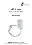
USB Gateway for MPI/PPI/PROFIBUS
700-892-MPI21
User Manual
Edition 2 / 06.04.2010
HW 1-1b and FW 2.30 and higher
Order number of manual: 900-892-MPI21/en
Systeme Helmholz GmbH z Hannberger Weg 2 z 91091 Großenseebach
Fon: +49 9135 7380-0 z Fax: +49 9135 7380-110 z E-Mail: [email protected] z Internet: www.helmholz.de
All rights are reserved, including those of translation, reprinting, and
reproduction of this manual, or parts thereof. No part of this manual
may be reproduced, processed, copied, or transmitted in any way
whatsoever (photocopy, microfilm, or other method) without the
express written permission of Systeme Helmholz GmbH, not even
for use as training material, or using electronic systems. All rights
reserved in the case of a patent grant or registration of a utility
model or design.
Copyright © 2009 by
Systeme Helmholz GmbH
Hannberger Weg 2, 91091 Grossenseebach, Germany
Note:
We have checked the content of this manual for conformity with
the hardware and software described. Nevertheless, because deviations cannot be ruled out, we cannot accept any liability for complete conformity. The information in this manual is regularly updated. When using purchased products, please heed the latest version of the manual, which can be viewed in the Internet at
www.helmholz.de, from where it can also be downloaded.
Our customers are important to us. We are always glad to receive
suggestions for improvement and ideas.
STEP, S7-200, S7-300, S7-400, Protool, Starter, Micromaster, and SIMATIC are registered trademarks of SIEMENS AG
MS-DOS and Windows are registered trademarks of Microsoft Corporation.
Revision history of this document:
Edition
Date
Revision
1
20.10.2009
First edition
2
06.04.2010
Section 5 new structured
Contents
®
NETLink USB Compact
1
Safety Information
7
1.1
General
7
1.2
Restriction of access
8
1.3
Information for the user
8
1.4
Use as intended
8
1.5
Avoiding use not as intended!
8
2
System Overview
9
2.1
Application and function description
9
3
Installation and Mounting
10
3.1
Connections
10
3.2
LED displays
10
3.3
Items supplied
11
3.4
3.4.1
3.4.2
Accessories
Manuals
Software
11
11
11
4
Installation of the driver software
12
4.1
Introduction
12
4.2
System requirements
12
4.3
4.3.1
4.3.2
Running the installation setup
Adding the interface to the PG/PC interface
Selecting the required interface parameterization
12
13
14
4.4
Installation of the USB driver
15
5
Configuration via the NETLink-S7-NET Driver
18
5.1
5.1.1
5.1.2
5.1.3
Bus settings
MPI
PROFIBUS configuration
PPI configuration
18
19
20
23
5.2
5.2.1
5.2.2
Options of the driver
Language setting of the display elements
Version information
23
24
24
5.3
5.3.1
Diagnostics
Bus members
24
24
5
6
5.3.2
Bus parameters
25
6
Troubleshooting
26
7
Appendix
28
7.1
Technical data
28
7.2
7.2.1
7.2.2
Pin assignments
MPI/PPI/PROFIBUS interface pin assignments
Assignment of the USB interface
29
29
29
7.3
Further Documentation
29
8
Glossary
30
®
NETLink USB Compact
1
Safety Information
For your own safety and for the safety of others, always heed the
safety information given here. The safety information indicates
possible hazards and provides information about how you can
avoid hazardous situations.
The following symbols are used in this manual.
!
i
Caution, indicates hazards and sources of error
Gives information
Hazard, general or specific
Danger of electric shock
1.1
General
®
The NETLink USB Compact is only used as part of a complete system.
!
The operator of a machine system is responsible for observing
all safety and accident prevention regulations applicable to the application in question.
During configuration, safety and accident prevention rules specific to the application must be observed.
Emergency OFF facilities according to EN 60204 / IEC 204
must remain active in all modes of the machine system. The system
must not enter an undefined restart.
Faults occurring in the machine system that can cause damage
to property or injury to persons must be prevented by additional external
equipment. Such equipment must also ensure entry into a safe state in
the event of a fault. Such equipment includes electromechanical safety
buttons, mechanical interlocks, etc. (see EN 954-1, risk assessment).
Never execute or initiate safety-related functions using an
operator terminal.
®
NETLink USB Compact
7
1.2
Only authorized persons
must have access to the
modules!
The modules are open components and must only be installed in a
PG or PC. Because the components on the boards are very sensitive
to electrostatic discharges, access to the closed PG/PC housing is
only permitted using the appropriate tools or keys and only to instructed and authorized persons.
1.3
During configuration,
safety and accident
prevention rules specific
to the application must
be observed.
Restriction of access
Information for the user
This manual is addressed to anyone wishing to configure, use, or
®
install the NETLink USB Compact.
®
The manual tells the user how to operate the NETLink USB Compact and explains the signaling functions. It provides the installing
technician with all the necessary data.
®
The NETLink USB Compact is exclusively for use with a S7-200
and S7-300/S7-400 programmable controller from Siemens.
®
The NETLink USB Compact is for use within a complete system
only. For that reason, the configuring engineer, user, and installing
technician must observe the standards, safety and accident prevention rules applicable in the particular application. The operator of
the automation system is responsible for observing these rules.
1.4
Use as intended
®
The NETLink USB Compact must only be used as a communication and signaling system as described in the manual.
1.5
Avoiding use not as intended!
®
Make sure in the
software that
uncontrolled restarts
cannot occur.
8
Safety-related functions must not be controlled via the NETLink
USB Compact alone. Make sure in the software that uncontrolled
restarts cannot occur.
®
NETLink USB Compact
2
System Overview
2.1
Application and function description
®
The NETLink USB Compact is a gateway between USB and an MPI,
PPI, or PROFIBUS.
With one USB connection (12 Mbps full speed or 480 Mbps high
speed), up to 32 MPI/PROFIBUS connections (9.6 kbps to 12 Mbps)
can be used simultaneously.
At both the USB and the field bus ends, the baudrate used can be
determined automatically (autodetect or autobaud)
®
The NETLink USB Compact draws its 5-volt power supply from
the USB interface of the PG/PCs.
®
The NETLink USB Compact has the shape of a PROFIBUS connector with a PG female connector and it is plugged directly into the
MPI/PPI/PROFIBUS interface of the automation system. Because it
is active, no spur line is created that could interfere with the bus.
®
The USB end of the NETLink USB Compact is electrically isolated
from the MPI/PPI/PROFIBUS.
®
The NETLink USB Compact is connected to the PG/PC by the 3m
long USB 2.0 cable that is permanently attached to the housing.
The USB cable can be extended, for example, using a self-powered
USB hub.
®
The use of drivers makes it possible to use the NETLink USB
Compact at the PC end as a
•
Programming adapter or
•
Operator control and monitoring unit
The transmission rates of USB 1.1 and USB 2.0 are supported.
®
NETLink USB Compact
9
3
Before you start
installation work, all
system components must
be disconnected from
their power source.
Installation and Mounting
Installation must be effected in compliance with VDE 0100 / IEC
®
364. The NETLink USB Compact has degree of protection IP20.
Please ensure a maximum ambient temperature of 60 ºC for reliable operation.
®
The NETLink USB Compact is plugged directly into the SUB D
female connector of the PROFIBUS station instead of the standard
PROFIBUS device connector. It is fixed using the permanently integrated hexagon-head housing screws and therefore makes permanent contact.
Further bus nodes for diagnostic devices can be connected to the
integrated PG female connector.
Only the USB communication cable is permanently mounted on
®
NETLink USB Compact housing. No further outlets, for example,
PROFIBUS cable, can be connected to the device. Therefore no
termination is possible on the connector housing and the
"ON/OFF" switch for this is not been incorporated.
3.1
Connections
®
The NETLink USB Compact has the following connections:
• USB 2.0 cable with standard A connectors for connecting the device to commercially available PG/PCs or hubs.
• Bus connector with PG female connector This enables further
bus nodes to be plugged in.
®
The NETLink USB Compact is an ‘active cable.’ This means
there is no spur line, which avoids interference with high baud
rates.
3.2
LED displays
®
For display of the operating state, the NETLink USB Compact has
two multi-colored LEDs. These are located on the front of the
housing behind a white inspection window.
LED status for operating
status
10
Power LED
(blue)
Bus LED
(orange)
Active LED
(green)
Ready for operation
ON
Try to log on to the
MPI/PPI/PROFIBUS
ON
Actively logged on to the
MPI/PPI/PROFIBUS
ON
ON
Data exchange with a
programmable controller
ON
BLINK
Transferring firmware
update
ON
Bus LED
(red)
BLINK
BLINK
®
NETLink USB Compact
3.3
Items supplied
®
The scope of supply of the NETLink USB Compact includes:
• NETLink USB Compact ready to run
®
• CD with NETLink -S7-NET driver, additional info
®
• Manual (German/English)
3.4
Accessories
3.4.1
Manuals
Manual, German
900-882-MPI21/de
Manual, English
900-882-MPI21/en
3.4.2
Software
S7/S5 OPC server with USB dongle
®
NETLink USB Compact
800-880-OPC20
11
4
Installation of the driver software
®
®
With installation of the NETLink -S7-NET driver for the NETLink
USB Compact, it is easy to access controllers with an MPI, PPI, or
PROFIBUS interface from the PC via USB.
4.1
Introduction
®
The NETLink -S7-NET driver is inserted in the PG/PC interface of
an existing Simatic application and can then be used from most
Simatic engineering tools (STEP7, ProTool, WinCC, etc.).
Access is possible to any controllers of the Simatic S7-200, S7-300,
or S7-400 series. To connect a Simatic S7-200, S7-300, or S7-400
®
controller, the communication adapter NETLink USB Compact
and a corresponding MPI/PPI/PROFIBUS cable is required.
4.2
System requirements
A PC with a 32-bit Windows operating system is required to oper®
ate the NETLink -S7-NET driver at the PG end. The Windows 2000,
Windows XP, and Windows Vista operating systems can be used.
A further requirement is the existence of a Simatic engineering
tool, such as STEP7, Version 5.1 and higher or STEP7-Micro/Win
Version 4.0 and higher, which ensures that the PG/PC interface is
installed on the computer.
Installation under Windows 98/ME/NT is possible but is not supported by the technical support team of Systeme Helmholz GmbH.
Please pay attention to the requirements of the Simatic package
used.
The PG/PC used must contain at least one (internal or external)
functioning USB interface. The best performance is achieved using
an interface complying with USB 2.0 (high speed at 480 Mbps).
USB interfaces that only achieve full speed (12 Mbps) are also possible, but this slows down status operation.
4.3
Running the installation setup
After you have inserted the installation CD, user guidance starts
automatically, allowing the user to start the setup routine of the
®
®
NETLink -S7 -NET driver.
If the user guidance does not start automatically, the setup file can
be launched manually in directory ‘CD drive:\Driver\.’
Administration rights
are required for
installation.
12
®
If necessary, you can download the latest NETLink -S7-NET driver
from our homepage (http://www.helmholz.com).
Please note that for installation you have to log on as an administrator under the 32-bit Windows operating systems Win®
®
dows 2000 and Windows XP because the setup program has to
make entries in the Windows registry.
®
NETLink USB Compact
4.3.1
Adding the interface to the PG/PC interface
®
After initial installation, the new interface parameter set ‘NETLink S7-NET USB’ has to be set up. Administrator rights are necessary for
this.
After you have started ‘Set PG/PC Interface’ in the Control Panel,
click the ‘Select…’ button there.
This opens the ‘Install/uninstall interface’ dialog box.
®
After you have selected the entry ‘NETLink -S7-NET USB’ from the
left-hand list, click the ‘Install’ button.
®
NETLink USB Compact
13
®
Now you have answered the query, ‘NETLink -S7-NET USB’ will
appear in the right-hand list with the interfaces already installed.
The access path in the ‘Set PG/PC Interface’ dialog box is set when
this window is closed.
4.3.2
Selecting the required interface parameterization
The selection list for the interface parameter sets now contains an
®
additional three items for the NETLink USB Compact.
®
All relevant settings of a NETLink -S7-NET driver can be made via
the ‘Properties’ access field. With the button ‘Diagnostics...,’ it is
possible to show the nodes connected to the bus and the parameters the bus is working with. These fields are explained in Section
5.
14
®
NETLink USB Compact
4.4
Installation of the USB driver
®
If this is the first time a NETLink USB Compact is being connected
to the PC, the operating system will try to install a suitable driver.
The driver is a sort of interface between the USB interface and the
operating system (Windows) and has nothing to do with the actual
®
application (NETLink -S7-NET).
This initialization can take some time and goes through the following steps:
®
NETLink USB Compact
•
The operating system starts an installation wizard that performs the installation, which is largely automatic. Here it is
necessary to specify that the source for the USB driver should
not be ascertained automatically.
•
The next step is a prompt to specify the location of the driver.
15
It is generally enough to set a checkmark next to ‘Search removable media…’ and then to click the ‘Next’ button.
•
16
The system now searches for the driver.
®
NETLink USB Compact
•
If the NETLink-S7-NET CD is inserted in a local drive, installation should start after a short time.
•
After successful installation, the operation is completed by
clicking the ‘Finish’ button.
®
The NETLink USB Compact has been successfully installed and
can now be used.
®
As long as the NETLink USB Compact is always operated on the
same USB interface in your PG/PC, the driver files of the operating
system are not queried again.
®
NETLink USB Compact
17
5
Configuration via the NETLink-S7-NET Driver
®
Once a NETLink USB has been selected in the ‘Set PG/PC Interface’
window, it is possible to specify this access path more precisely
with the ‘Properties…’ button.
With the functionality behind the button ‘Diagnostics...,’ which is
®
visible when a NETLink USB is selected, it is possible to read the
bus configuration and scan connected nodes.
®
The following properties of the access NETLink USB are available:
• Bus settings
Here it is possible to state the bus configuration (e.g. station ad®
dress) with which the NETLink USB Compact will enter the bus
system (Section 5.1).
• Options
Here it is possible to change the language of the NETLink-S7NET driver and to read out the version information of the driver
(Section 5.2).
Two functionalities are implemented for diagnostics at the connected bus:
• Bus members
a list of all active and passive nodes connected to the bus will be
displayed. By request the order numbers (MLFBs) will be displayed also if this functionality is available by the nodes (Section 5.4.1).
• Bus parameters
If possible, a list of all available bus parameters will be displayed
(Section 5.4.2).
5.1
Bus settings
®
The NETLink USB Compact can be operated on three different bus
systems: MPI, PPI, and PROFIBUS.
®
From the NETLink USB Compact user’s viewpoint, the three bus
systems only differentiates by the transmission rates that can be
selected and the additional options which are explained here.
®
The bus configuration is passed to the NETLink USB Compact
during the runtime of the NETLink-S7-NET driver and is not stored
in the device.
®
It is possible to use the NETLink USB Compact without specifying
®
bus-related information. The NETLink USB Compact then automatically ascertains the baud rate and the bus parameters, and can
be operated on different programmable controllers with different
transmission rates without switching over the NETLink-S7-NET
driver.
18
®
NETLink USB Compact
5.1.1
MPI
The MPI configuration contains station and network-related settings.
The most important setting concerning bus configuration is assignment of the station address. This refers to the address the NET®
Link USB Compact will have on the bus when it goes online.
The station address can have any value from ‘0’ and ‘126’ if the
selected address is lower than or equal to the highest station address (HSA).
Example:
HSA = 31
Any value between ‘0’ and ‘31’ can be specified for the station address if this address does not yet exist on the bus.
The local timeout of the NETLink-S7-NET driver can be parameterized in the station-related settings. If the driver does not receive
a response to a request within the set timeout, a communication
error is signaled to the Simatic application.
The network settings can be adapted manually if the checkmark
next to “Automatic Baud Rate Detection” is removed. This is usually
®
only necessary if the NETLink USB Compact fails to sign onto the
bus system automatically (can happen with passive bus nodes).
®
NETLink USB Compact
19
Some older Siemens CPUs do not support the auto baud function
on the MPI. PPI systems do not usually support this function either. In such cases, the network-related parameters should be
adapted manually.
The transmission speed and the HSA of the PLC being addressed
must be known and identical to all connected bus nodes.
It is also possible that the auto baud function may not function reliably at transmission rates slower than or equal to 19.2 Kbps or
with increased use of communication via global data exchange,
because the relevant frame is transmitted more irregularly by the
CPUs. In such cases it may be advantageous to assign the bus parameters manually.
5.1.2
PROFIBUS configuration
Basically, the same applies to PROFIBUS configuration as to MPI
configuration. However, the network-related parameters are more
extensive.
In addition to the parameters transmission rate and highest station
address mentioned in Section 5.1.1, PROFIBUS also has parameter
field for selecting the bus profile and bus parameters.
®
If the NETLink USB Compact is the only active station on the
PROFIBUS, it operates in so-called single-master mode, i.e. it generates the token cycle with the set bus parameters.
If the bus speed on the PROFIBUS is set to a value less than 187.5
Kbps, please remember that it may take up to half a minute for the
bus parameters to be recognized.
20
®
NETLink USB Compact
In this case, the timeout value should be increased correspondingly.
Profile:
• Under PROFIBUS, there are usually the profiles DP, Standard und
User defined.
• The profile must be selected that is already used in the programmable controller.
Bus parameters:
• Unlike the MPI bus profile, the bus parameters for PROFIBUS are
not constant and change with the type and number of
PROFIBUS stations used.
• Always set the PROFIBUS parameters that are set in the currently
used programmable controller (see current STEP7 project).
In order to simplify these procedures, it makes sense to use of the
auto baud function under PROFIBUS.
®
NETLink USB Compact
21
The bus parameters are then calculated automatically.
Under PROFIBUS, please note that the auto baud function works
best if the ‘Cyclic distribution of the bus parameters’ function is activated in the programmable controller used.
The screenshot above of a hardware configuration of a randomly
chosen PROFIBUS CPU shows where to find the switch for cyclic
distribution of the bus parameters.
22
®
NETLink USB Compact
5.1.3
PPI configuration
Basically, the same applies to PPI configuration as to MPI configuration. However, the network-related parameters are more extensive.
!
Normally the baud rate
cannot be detected automatically at PPI systems.
In addition to the parameters transmission rate and highest station
address mentioned in Section 5.1.1, PROFIBUS also has a parameter field for selecting the bus profile and bus parameters:
According to current knowledge, all S7-200 CPUs of the product
line 22x should be able to communicate with ‘Advanced PPI.’ It is
recommended to use ‘Advanced PPI’ if possible.
5.2
Options of the driver
Under the options of the NETLink-S7-NET driver, it is possible to
set the language of the output and help texts of the driver.
®
NETLink USB Compact
23
It is also possible to read out the version numbers of the driver files
used.
5.2.1
Language setting of the display elements
The languages German and English are currently available.
After switching over the language, the setting window must be
opened again to apply the changes.
5.2.2
Version information
The names and version number of all driver files are listed here.
If support is needed, this data is used to obtain information about
the components used quickly and effectively.
5.3
Diagnostics
For rudimentary diagnostics of the connected bus two sub functions are available:
• Display bus nodes
• Display bus parameters
Before the diagnostics functionality is used, a valid station must be
created and a plausible bus configuration set.
5.3.1
Bus members
A list of all available nodes at the bus will be generated by clicking
the button ‘Read.’
With activating the option ‘Read MLFB number’ the order numbers
of all devices supporting this function will be displayed too.
The possibility to detect all connected nodes depends on the
parameterization of the PG/PC Interface.
24
®
NETLink USB Compact
It is recommended to enable auto baud functionality at MPI and
PROFIBUS.
5.3.2
Bus parameters
If it is possible a list of all bus parameters will be displayed by
clicking the button ‘Read.’
The possibility to detect the bus parameters depends on the
parameterization of the PG/PC Interface.
It is recommended to enable auto baud functionality at MPI and
PROFIBUS.
®
NETLink USB Compact
25
6
Troubleshooting
The points described here show some typical errors that can occur
®
in day-to-day work with the NETLink USB Compact.
If any condition during operation is not described here and this
manual does not provide any information on how to remedy it,
the support of Systeme Helmholz GmbH is available to help you.
Q: Although I have already operated a NETLink USB Compact on
my PC, I am prompted to install a USB driver if I want to use another NETLink USB or another USB interface of my PC.
A: USB devices are usually equipped with a serial number. This is
used to identify devices that are already known.
If you use two USB devices of the same type, two instances of the
driver will be installed on your computer for this device type.
You will find the USB driver on the CD supplied in directory ‘CD
directory:\Driver’. You can also download it from our homepage at
www.helmholz.de.
Q: During the usage of a NETLink USB Compact on an external
hub or a separate USB card it comes to unexpected errors. Disconnecting and reconnecting the USB cable between NETLink USB and
hub does not clear the situation.
A: Is e.g. the power supply of the hub too powerless for the NETLink USB Compact, some of the hubs on the marked providing an
error to the host system (the pc). This triggers a logical disconnection of the hub from the host – the host is not functioning anymore.
After a physically disconnect of the hub from the host and a reconnection to the host the hub should work again.
To solve the problem with the NETLink USB Compact use an external power supply for this device.
Q: The setting dialog boxes are not appearing in the Simatic Manager:
A: Please note that after initial installation the NETLink®-S7-NET
driver must be added to the PG/PC interfaces.
Make sure you had administrator rights during installation. Reboot
your PC after installation if prompted to do so.
You need at least version 5.1 of the Simatic Manager.
Q: When the connection to the PROFIBUS is plugged in, no online
connection is possible.
A: If possible, use the autobaud functionality.
If this is not possible or not desired, check the timing parameters
for the PROFIBUS in the STEP7 configuration. Enter the read values
into the advanced bus parameter settings via the ‘Bus parameters’
button. If on-line access is still not possible, set a higher ‘Ttr’ (target rotation time) both in the NETLink USB Compact and on the
CPU.
Q: The Starter program has problems accessing a Micromaster
drive.
26
®
NETLink USB Compact
A: When you request a ‘control priority’ for the Micromaster drive,
please increase the Failure monitoring from 20ms to 200ms and
the Application monitoring from 2000ms to 5000ms, so that the
Starter software remains operable.
®
Q: If I set the NETLink USB Compact to autobaud in the PG/PC
interface and try to go online, the orange LED lights up briefly before a message appears telling me that the bus parameters cannot
be determined.
A: Either the CPU used does not support the cyclic transmission of
bus parameters (disabled via parameterization or function does not
exist), or the CPU is so busy with general communication tasks
that the lower-priority bus parameter frame is transmitted too in®
frequently and cannot be detected by the NETLink USB Compact.
®
Please deactivate the autobaud functionality in the NETLink -S7NET driver (PG/PC interface) and set the correct baudrate and the
correct profile manually.
Q: If I open multiple connections via the STEP7 driver, the link
sometimes breaks off or error messages appear saying that it is not
possible to establish a link.
A: For communication with S7-300 modules it may be necessary to
parameterize the communication resources.
The user can influence the allocation of existing ‘connection resources’ under object properties of the CPU in the hardware configuration.
Q: Once the configured PROFIBUS slaves have been added on my
®
CPU, communication between NETLink USB Compact and STEP7
becomes markedly slower.
A: The user can influence the allocation of ‘cycle load due to communication [%]’ under object properties of the CPU in the hardware
configuration. The default value is 20 %.
Q: What must I observe when calling your technical support?
A: Please have all relevant data of your system constellation with
the connected stations and program modules at hand when you
contact technical support at Systeme Helmholz GmbH.
®
NETLink USB Compact
27
7
7.1
Appendix
Technical data
Dimensions in mm (LxWxH)
64 x40 x 17
Weight
Approx. 110 g
Operating voltage / current consumption
5 V DC, 500 mA (USB)
Automatically selected
USB port
USB 2.0 (high speed), downward compatible
with USB 1.1
USB connector
USB A connector
USB transmission rate
12 Mbps (full speed) and
480 Mbps (high speed)
MPI/PPI/PROFIBUS interface
RS485, electrically isolated
MPI/PROFIBUS transmission rate
(automatic detection)
9.6 Kbps;
45.45 kbps
187.5 kbps
1.5 Mbps
6 Mbps
MPI/PROFIBUS connection
SUB D connector, 9-way
with PG- interface
MPI/PROFIBUS protocols
FDL protocol for
MPI and PROFIBUS
Displays
2 LEDs, including 1 three-color LED, for
general status information
Degree of protection
IP 20
Operating temperature
0 °C ... 60 °C
19.2 kbps
93.75 kbps
500 kbps
3 Mbps
12 Mbps
Storage and transportation tempera-25 °C to +75 °C
ture
28
Relative humidity during operation
5 % to 85 % at 30 ℃ (no condensation)
Relative humidity during storage
5 % to 93 % at 40 ℃ (no condensation)
®
NETLink USB Compact
7.2
Pin assignments
7.2.1
MPI/PPI/PROFIBUS interface pin assignments
Connector Signal
Meaning
1
-
Unused
2
GND
Ground
3
RxD / TxD-P
Receive / transmit data-P
4
RTS-AS
Transmit request from AS
5
DGND
Ground for bus termination
6
DVCC
5 V DC for bus termination
7
VCC
24 V DC (available only in the case of power
supply via connector P1)!
8
RxD / TxD-N
Receive / transmit data-N
9
RTS-PG
Transmit request to AS
7.2.2
Assignment of the USB interface
Connector
Signal
Meaning
1
VCC
5 V DC
2
D-
Data -
3
D+
Data +
4
GND
Ground
A shielded USB 2.0 cable is permanently connected to the NET®
Link USB Compact. It is three meters long and ends in a typeA USB connector.
As a rule, for USB, the cable length between two USB interfaces
should not be longer than three meters. Minimization of the
voltage drop in the cable is a decisive factor for smooth
operation of the connected devices for a 5-volt power supply.
If larger distances have to be covered, the use of USB hubs is
recommended.
7.3
Further Documentation
Internet:
http://www.helmholz.de
http://www.profibus.com
http://www.usb.org
http://www.siemens.com
®
NETLink USB Compact
29
8
Glossary
These are explanations of the most important technical terms
and abbreviations from the manual.
Advanced
PPI
The extension of the PPI protocol of the S7-200 series, normally only compatible with CPUs of the S7-22x series and higher
ASCII
American Standard Code for Information Interchange describes a character
set that includes the Latin alphabet in upper and lower case, the ten Arabic
numerals, as well as some punctuation marks and control characters
Autobaud
Also called "auto sensing," is a function supporting automatic adjustment of
the baud rates in a network
Baudrate
The speed set on a bus system
Bit
Binary digit describes the smallest digital information unit. Defines 0 or 1
Bus
Buses are connection systems for electronic components. For example, the
MPI Bus is a connection medium for S7
Byte
A byte denotes a series of 8 bits that constitute a logical data entity
Client
A device that requests services. The requests are sent to a server, which returns the relevant answers to the client.
Computer
In this manual, this refers to the programmer (PG) or personal computer
(PC).
Firewall
A service running on a server that blocks certain services/ports and prohibits
unauthorized access
Full speed:
Definition of the interface speed to 12 Mbit/s
Gap
The Gap Update Factor specifies after how many token cycles the master
checks whether an additional master is signaling its presence on the bus
High speed
Definition of the interface speed to 480 Mbit/s
HMI
Human-Machine Interface denotes the interface between the human operator and a system through which the operator can operate the system or
intervene in the process
HSA
Highest station address that is polled
Hub
A mediation system to connect several segments. Can optional operate with
its own power supply, to achieve longer distances via USB
Host
A computer system that provides services as an active or “smart” part for
other connected client devices
Interfaces
General definition of interfaces, such as a network interface card that constitutes an Ethernet interface
Low speed
Definition of the interface speed to 1,5 Mbit/s
Master
Is and active station that is permitted to transmit data to and request data
from other stations, when it holds the token
MLFB
16-digit Siemens identification number
MPI
Multipoint Interface. Interface that is used for S7-300 and S7-400 systems
and that supports baud rates up to 1.5 Mbps
30
®
NETLink USB Compact
OPC
Object Linking and Embedding for Process Control allows data transfer between applications of different producers, for example, using the RFC1006
protocol
PG socket
The programming unit socket of the bus connector allows further bus nodes
to be plugged in.
PPI
Point-to-point interface, interface with S7-200 systems with a maximum
baud rate of 187.5 kbps
PROFIBUS
Process Field Bus is the protocol that is used mainly for automation, e.g. for
the S7-300 and S7-400 systems with a maximum baud rate of 12 Mbps
Profinet
Standard for industrial Ethernet in automation.
Rack/Slot
Rack refers to the configured module rack (default: 0) and slot, to the slot for
the module in question (default CPU: 2). The default configuration for an
R/S is therefore 0/2
Retry limit
Bus parameter that determines the number of attempts will be made to call
a DP slave
SCADA
Supervisory Control and Data Acquisition. Generic term for a type of process visualization that includes monitoring, control, and data acquisition of
automation systems, etc.
Server
A device that provides special services at the request of clients.
Single
master
Only one master is connected to the system. The NETLink family members
WLAN, Switch, and PRO Compact can also act as single masters
Slave
A station that is only permitted to exchange data with the master if requested to do so by the latter.
Timeout
Defines a protocol instruction that is activated if a defined time has been
exceeded
Token
Is a frame for permission to transmit in a network. It is passed from master
to master
Tqui
Transmitter fall time (bit) is the time that is needed to restore the quiescent
signal level on the signal line after transmitting data
TSAP
Transport Service Access Point. The TSAP corresponds to the layer 4 address
that has to match crossed-over for a station and the communication partner
to be reached. The remote TSAP of Station1 is equivalent to the local TSAP
of Station2. Entry of any characters, e.g. numerals is possible
Tsdr
Protocol processing time of the responding station (station delay responder)
Tset
The setup time (bit) is the time that is allowed to elapse between transmitting and receiving telegrams
Tslot_Init
The slot time (bit) is the maximum time that a transmitter waits for a station it has addressed to respond
Ttr
Target rotation time (Bit) is the reference token time. This means teh reference and actual token times are compared. This difference determines how
much time is available to the master to transmit its own telegrams to the
slaves
USB
Abbr. for Universal Serial Bus. Standard for a variety of of peripheral devices.
They can be embedded at the system runtime (hot plugging)
®
®
NETLink USB Compact
31
USB 1.1
Specification, which defines the maximum data rate of 12 Mbit/s
USB 2.0
USB 1.1 successor specification with a higher date rate to 480 Mbit/s
USB Hub
See Hub
Wizard
A step by step startup help to simplify a driver installation for the user
Notes
32
®
NETLink USB Compact


