1
micro2R and N1MM Logger+ Setup
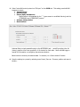
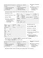
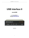
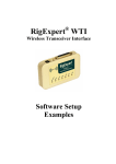
Router setup:
Note: The specific port numbers are not important. The key is consistency - the same port
number must be used for a specific function in both Router and the logger.
micro2R does not provide transceiver control. You will need a CAT/CI-V interface for each radio. They can
be anything from traditional serial ports to microHAM microKEYER II. Typical configurations are shown in
the micro2R User Manual.
1. Assign a port for Control. N1MM Logger+ will use this port to select transmit and receive focus.
2. Assign ports for FSK and check the PTT box. Check the “Stuff” box (diddle stuffing) if you will be
using a COM port from MMTTY or the FSK8250 driver with MMVARI. Uncheck the “Stuff” box if
you will be using 2-Tone FSK or EXTFSK with MMTTY/MMVARI.
Suggestion: If you are using microHAM CAT/CI-V interfaces, use the FSK ports in those devices
instead of FSK in micro2R.
3. Assign a port for WinKey. Set “Use WinKey PTT” on the PTT & ACC tab.
4. Set “Generate PTT Output” on the PTT & ACC tab.
5. Select “microHAM control protocol on COM port” on the SO2R tab. This setting permits N1MM
Loggger to control:
Transmit focus
Receive Focus
Stereo (Split) Headphones
Stereo receive is commanded by the “`” (grave accent or unshifted tilde key) and the
{STEREOON} and {STEREOOFF} macros.
Antenna (Relay) Select
Band Lockout
Antenna Relay is simply passed through to the ACCESSORY jack. micro2R provides a four bit
(binary) signal to drive a user supplied 1 of 16 decoder for each radio. See the N1MM Logger+
manual for information on configuring the antenna selections.
Band Lockout is driven by the antenna data. In essence, it is a “same antenna” lockout.
6. Save the settings to a preset by selecting menu Preset | Save as. Choose a position and name it
N1MM+.
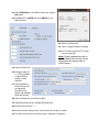
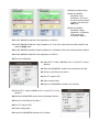
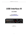
N1MM hardware setup:
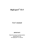
1. Click Config| Configure Ports, Mode
Control, Audio, Other ...
2. Assign each radio to the proper COM port
(hardware serial port or USB adapter).
Note: The radio ports are not supported by
micro2R and are not created in microHAM Router.
Use your own serial ports or USB converters.
3. For each radio port click Set and configure
the communication parameters for your
radios.
4. For both radios, set RTS (pin 7) and DTR
(pin 4) to Always Off, Uncheck “Enable
Both Hardware & Software” and DO NOT
check any of the "PTT via Radio Command"
options.
5. Check Digital for each port defined as FSK in
Router.
6. Configure the Digital ports, taking care to
associate each port with the correct Radio
(Radio Nr) and Digital Interface (Dig Wind
Nr).
7. Set DTR and RTS to "always Off".
8. Check CW/Other on the port you created for
WinKeyer 2 in Router.
9. Click Set, set Radio Nr = Both and check
WinKey.
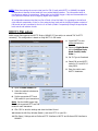
10. Check CW/Other for the MK2R Control port, click the
Set button.
11. Set Radio/VFO to BOTH and select MK2R for Two
Radio Protocol.
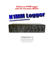
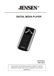
12. Select the WinKey tab.
13. "Use 2nd Output" should be checked
14. Pin 5 Function should be PTT unless
you are using QSK
Note: Timing parameters are set on
the CW/WinKey tab in Router. Router
will override any settings made in
N1MM Logger+.
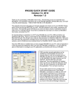
15. Select the Audio tab.
16. Configure Audio for
"1 – Only use Radio
1 Output Device:
Output on both
channels”
17. Select Speakers of
the sound card you
are using with
micro2R as the
Output and Message
Recording Devices.
18. Select “Microphone” as the Port to Mute
19. Select Microphone as the Message Recording Port.
20. Set Recording Channels = 1
21. Set Recording Bits, Sample Rates and Max Recording Length as needed.
22. Click OK to save and close the N1MM Logger+ Hardware Configuration
NOTE: Other than setting the correct virtual port for FSK (if used) with MMTTY or MMVARI, the digital
configuration is identical to that used with your existing digital interface. The information below is
provided as a matter of convenience. Please refer to the N1MM Logger+ Help and documentation for
your particular interface when configuring digital mode support.
All configurations assume that the Line Out of Radio 1/Line Out Radio 2 is connected to the left and
right channels respectively of Line In of an external sound card and the Left/Right Speaker outputs of
that sound card are connected to the Line In of Radio 1/Radio 2 respectively through the appropriate
level control and isolation circuits.
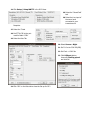
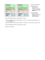
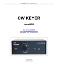
MMTTY FSK setup:
N1MM Logger Plus supports the MMTTY Engine, MMVARI, 2-Tone and/or an external TNC for RTTY
contesting. This configuration is based on using MMTTY in FSK mode.
1. Install MMTTY to two
different directories.
2. Select the Digital Modes
tab in Configure Ports,
Mode Control, Audio,
Other ...
3. Set TU Type to Soundcard
4. Select FSK as the MMTTY
mode for DI-1 and DI-2 if
using SO2V.
5. Enter the path to each
MMTTY installation.
6. Open the Mode Control tab
7. Select the method to determine
the mode to log.
8. Set the appropriate RTTY and
PSK modes for your transceivers.
Note: See the N1MM Logger Help
files for the supported RTTY and PSK
modes for each transceiver.
9. Click "OK" to save the settings and close the Mode Control.
10. Activate the left Entry Window (Radio 1) and enter RTTY to open DI 1.
11. Click Setup | Settings and set Preferred RTTY Interface to MMTTY and Preferred PSK Interface to
MMVARI.
12. Click Setup | Setup MMTTY in the DI-1 menu.
13. Select the "SoundCard"
tab.
14. Select the Line input of
the sound card
connected to your
transceivers for
Reception.
15. Select the TX tab
16. Set PTT & FSK to the port
used for Radio 1 FSK.
17. Select the Misc Tab
18. Set Source = Left
19. Set Tx Port to COM-TxD(FSK)
20. Set Clock = 12000 Hz
21. Click the USB port button,
choose C: Limiting speed
and click OK
22. Click "OK" on the Misc tab to close the MMTTY Set-up for
Radio 1
23. Activate the right Entry Window (Radio 2) and enter RTTY to open DI-2.
24. Click Setup | Setup MMTTY in the DI-2 Menu.
25. Select the "SoundCard"
tab.
26. Select the Line input of
the sound card
connected to your
transceivers for
Reception.
27. Select the TX tab
28. Set PTT & FSK to the port
used for Radio 2 FSK.
29. Select the Misc Tab
30. Select Source = Right
31. Set Tx Port to COM-TxD(FSK)
32. Set Clock = 12000 Hz
33. Click USB port button,
choose C: Limiting speed
and click OK
34. Click "OK" on the Misc tab to close the Set-up for DI 2
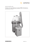
MMTTY setup (AFSK):
N1MM Logger Plus upports the MMTTY Engine, MMVARI, 2-Tone and/or an external TNC for RTTY
contesting. This configuration is based on using MMTTY in AFSK mode.
AFSK does not require a digital port for each radio. If you will be using only AFSK and PSK, it is not
necessary to define "Digital" ports on the N1MM "Hardware" tab or FSK ports in Router.
1. Install MMTTY to two
different directories.
2. Select the Digital Modes tab
in Configure Ports, Mode
Control, Audio, Other ....
3. Set the TU Type to
Soundcard
4. select AFSK as the MMTTY
mode for both DI-1 and DI-2.
5. Enter the path to each copy
of MMTTY.
6. Open the Mode Control tab
7. Select the method to determine
the mode recorded in the log.
8. Set the appropriate RTTY and
PSK modes for your
transceivers.
Note: See the N1MM Logger Plus Help files for a list of supported RTTY and PSK modes for each
transceiver.
9. Click OK to Close the Mode Control window and save the configuration.
10. Activate the left Entry Window (Radio 1) and enter RTTY to open DI 1.
11. Click Setup | Settings and set Preferred RTTY Interface to MMTTY and Preferred PSK Interface to
MMVARI.
12. Click Setup | Setup MMTTY in the DI-1 menu.
13. Select the "SoundCard"
tab.
14. Select the Line input of
the sound card
connected to Radio 1
for Reception.
15. Select the Speaker output of the sound card connected to Radio 1 for Transmission.
16. Select the TX Tab
17. Set PTT & FSK Port = None
18. Check TX BPF
19. Set Tap = 512 and Freq =
100 Hz to filter the
transmitted audio and
minimize QRM.
20. Select the Misc Tab
21. Select Source = Left
22. Set Clock = 12000 Hz
23. Set Tx Port to Sound.
24. Click "OK" to close MMTTY Set-
up for Radio 1
25. Activate the right Entry
Window (Radio 2) and Enter
RTTY to open DI 2.
26. If necessary, click on Interface | MMTTY to activate the MMTTY interface.
27. Click Setup | Setup MMTTY in the DI-2 menu.
28. Select the "SoundCard"
tab.
29. Select the Line input of
the sound card
connected to Radio 2
for Reception.
30. Select the Speaker output of the sound card connected to Radio 2 for Transmission.
31. Select the TX Tab
32. Set PTT & FSK Port = None
33. Check TX BPF
34. Set Tap = 512 and Freq =
100 Hz to filter the
transmitted audio and
minimize QRM.
35. Select the Misc Tab
36. Select Source = Right
37. Set Clock = 12000 Hz
38. Set Tx Port to Sound
39. Click "OK" to close MMTTY
Setup for Radio 2.
FSK/PSK31 with MMVARI:
N1MM Logger supports the MMTTY Engine, MMVARI, 2-Tone and/or an external TNC for RTTY contesting. This
configuration is for FSK RTTY and PSK using MMVARI.
FSK requires a digital port for each radio (DI). Be sure you have defined Digital ports for each radio in the
N1MM "Hardware" tab and FSK ports in Router.
1. Select the Digital Modes tab
in Configure Ports, Mode
Control, Audio, Other ....
2. Set the TU Type to
Soundcard
3. select FSK as the MMVARI
RTTY mode for both DI-1 and
DI-2.
4. Set the FSK Port to FSK8250
for both DI-1 and DI-2
5. Open the Mode Control tab
6. Open the Mode Control tab
7. Select the method to determine
the mode to log.
8. Set the appropriate RTTY and PSK
modes for your transceivers.
Note: See the N1MM Logger Plus
Help files for the supported RTTY and PSK modes for each transceiver.
9. Click "OK" to save the settings and close the Mode Control.
10. Activate the left Entry Window (Radio 1) and enter PSK.
11. Click Setup | Settings and select MMVARI as the Default RTTY Interface and MMVARI as the Default
PSK Interface.
12. Select MMVARI Setup.
13. Select Soundcard Setup.
14. Set DI1 MMVARI
SoundCard: Input
Soundcard # to Liine of
the sound card connected
to Radio 1 and select the
Left Input.
15. Set DI1 MMVARI
SoundCard: Output
Soundcard # to Speakers
of the sound card
connected to Radio 1.
16. Set DI1 MMVARI SoundCard: Clock Adjustment to 12000 Hz.
17. Set DI2 MMVARI SoundCard: Input Soundcard # to “Liine of the sound card connected to Radio 2 and
select the Right Input.
18. Set DI2 MMVARI SoundCard: Output Soundcard # to “Speakers of the sound card connected to Radio 2.
19. Set DI2 MMVARI SoundCard: Clock Adjustment to 12000 Hz
20. Save the configuration.
21. Select RTTY-L mode in MMVARI in DI-1 or enter RTTY in Entry
Window 1
22. Select the MMVARIFSK1 window from the Windows Task Bar.
23. Set Port to the FSK port for Radio 1
24. Set PTT output to RTS
25. Check Limiting Speed
26. Return the MMVARIFSK1 window to the Task Bar.
27. Select RTTY-L mode in MMVARI in DI-2 or enter RTTY in Entry
Window 2
28. Select the MMVARIFSK2 window from the Windows Task Bar.
29. Set Port to the FSK port for Radio 2.
30. Set PTT output to RTS
31. Check Limiting Speed
32. Return the MMVARIFSK2 window to the Task Bar.
AFSK/PSK31 with MMVARI:
N1MM Logger supports the MMTTY Engine, MMVARI, 2-Tone and/or an external TNC for RTTY contesting. This
configuration is for AFSK RTTY and PSK with MMVARI.
AFSK and PSK do not require the use of a digital port for each radio. Do not configure a Digital Port in N1MM
Logger or a FSK Port in Router.
1. Select the Digital Modes tab
in Configure Ports, Mode
Control, Audio, Other ....
2. Set the TU Type to Soundcard
3. select AFSK as the MMVARI
RTTY mode for both DI-1 and
DI-2.
4. Open the Mode Control tab
5. Select the method to determine
the mode recorded in the log.
6. Set the appropriate RTTY and
PSK modes for your trnsceiver.
Note: See the N1MM Logger
Plus Help files for a list of
supported RTTY and PSK modes for each transceiver.
7. Click OK to Close the Mode Control window and save the configuration.
8. Activate the left Entry Window (Radio 1) and enter PSK.
9. Click Setup | Settings and select MMVARI as the Default RTTY Interface and MMVARI as the Default
PSK Interface.
10. Select MMVARI Setup.
11. Select Soundcard Setup.
12. Set DI1 MMVARI
SoundCard: Input
Soundcard # to Line of
the sound card connected
to Radio 1 and select the
Left Input.
13. Set DI1 MMVARI
SoundCard: Output
Soundcard # to Speakers
of the sound card
connected to Radio 1.
14. Set DI1 MMVARI SoundCard: Clock Adjustment to 12000 Hz.
15. Set DI2 MMVARI SoundCard: Input Soundcard # to Line of the sound card connected to Radio 2 and
select the Right Input.
16. Set DI2 MMVARI SoundCard: Output Soundcard # to Speakers of the sound card connected to Radio 2.
17. Set DI2 MMVARI SoundCard: Clock Adjustment to 12000 Hz
18. Save the configuration.