1
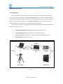
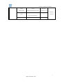
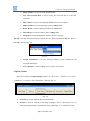
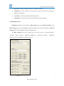
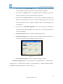
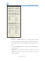
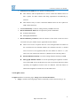
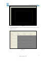
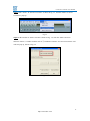
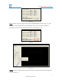
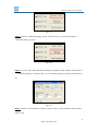
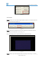
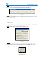
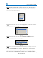
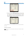
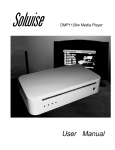
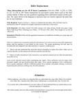
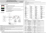
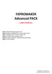
Colorbrate Charmer Users Manual Text Version. 1.0 ZHONGQING DIGITAL EQUIPMENT CO., LTD. Colorbrate® Charmer Users Manual CONTENTS Section 1 Overview .......................................................................................................................... 3 1.1 Introduction ......................................................................................................................... 3 1.2 Hardware and Software List................................................................................................ 4 Section 2 Software Description ...................................................................................................... 6 2.1 Drop-down menu ................................................................................................................ 7 2.2Quick Toolbar....................................................................................................................... 8 2.3 Parameter Area .................................................................................................................... 9 2.4 Graphics Area.................................................................................................................... 12 Section 3 Operating Instructions ................................................................................................. 14 3.1 Establish the environment ................................................................................................. 14 3.2 Into correction interface .................................................................................................... 14 3.3 Fill in the basic parameters ............................................................................................... 16 3.4 Correction.......................................................................................................................... 19 3.5 Optimization...................................................................................................................... 22 3.6 Save the correction date .................................................................................................... 25 3.7 Download the correction date ........................................................................................... 26 Section 4 FAQ ................................................................................................................................ 28 2 http://www.zdec.com Colorbrate® Charmer Users Manual Section 1 Overview 1.1 Introduction The non-uniformity of LED screen is caused by discreteness of the Light-Emitting Diodes. This is a problem that we all know. Colorbrate® Charmer is a very useful software tool which is specially designed to solve the above problem by correction of pixels one by one, thus to enhance the brightness uniformity of LED screen. Colorbrate® Charmer is one of the four main parts which constitute the correction sub-system of the V8A03 total solution. The correction sub-system of V8A03 solution consists of following four main parts and their connection is shown as Fig. 1-1. 1. Measuring Equipment: DSLR(Digital Single Lens Reflex) Camera 2. Controlling Equipments: Transmitting Card and Receiving Card 3. Correction Software: Colorbrate Charmer (Included in LED Manager 2010) 4. LED Cabinet (ready to be corrected) Fig. 1-1 3 http://www.zdec.com Colorbrate® Charmer Users Manual The correction process for uniformity of each LED Cabinet can be divided into the following three parts: 1) Control the DSLR Camera to take a photo for each LED Cabinet by running Colorbrate Charmer. 2) Colorbrate Charmer analyzes the luminance deviation of every pixel within the range of the LED Cabinet under correction and figures out automatically the correction coefficients for each LED in the range of the LED Cabinet under correction. 3) Download the correction data to the Receiving Card, through hardware structure which is specially designed for image processing algorithms, the luminance of every pixel is corrected automatically and the brightness of the screen become uniform. In addition, as the corrected coefficients are stored in Receiving Cards in the LED Cabinet, so that the cabinet can be located at random places, and the correction results are not affected by the installation site of the Cabinet. This makes the installation of the rental-screen much easy. 1.2 Hardware and Software List Type Name Description Fittings Remarks LED Manager 2010 8.1 and above ---- ---- Correction Software Transmitting ZQ-V8-TS01 USB cable、 M81GCA01 Card Transmitting Card ---DVI cable ZQ-V8-RV01 S81S1001 Receiving Card UTP5E ---- ---- ---- Receiving Card Operating System: Outsourcing PC Equipments Windows XP 4 http://www.zdec.com Colorbrate® Charmer Users Manual Canon Canon USB cable DSLR Camera 400D,450D,500D,50D,5D,60D CF Memory Card Offered by SINGMA APO 50-500mm Lens ---- customers F4-6.3Canon card port Tripod ---- ---- 5 http://www.zdec.com Colorbrate® Charmer Users Manual Section 2 Software Description The correction interface contains four parts: Drop-Down Menu, Quick Toolbar, Parameter Area and Display Area, shown as Fig.2-1. Fig. 2-1 Drop-Down Menu is used for calling some common functions, there are four button of drop-down menus at the top line under the title ∑Colorbrate Charmer of the frame: 【File】,【View】,【Tools】and【Help】. Quick Toolbar is used for correcting LED cabinet; there are six buttons on it: “Next Area”, “Zoom in”, “Live View”, “Calibration”, “Correction”, and “Check Effect”. Parameter Area has two features page marks: “Basic Setting” and “Advanced Setting”. “Basic Setting” page is used for filling the cabinet parameters and correction parameters; “Advanced Setting” page is used for filling the optimization parameters. Display Area has two features page marks: “Image” and “Correction Worksheet”. “Image” page is used for displaying photo. It is equivalent to a viewfinder of the camera. “Correction Worksheet” page is used for displaying each LED cabinet location in the LED screen. The detailed descriptions of these features are as follows. 6 http://www.zdec.com Colorbrate® Charmer Users Manual 2.1 Drop-down menu 【File】 :This drop-down menu has only one option: “Save Parameters”, shown as Fig. 2-2. Fig. 2-2 Save parameters is used for saving the parameters you filled in, if the software reset, you don‟t need to fill the filled parameters again. 【View】 :This drop-down menu has three options; they are “Open Test Image”, “Close Test Image” and “Extended Display”, shown as Fig. 2-3. Fig.2-3 Open test image is used for displaying a test image. Close test image is used for closing the test image. Extended display: If the graphics card works in extended mode, you must click this option. 【Tools】:This drop-down menu has seven options, they are “Quick Toolbar”, “Save V8 Correction Data”, “Take a Photo”, “Import a Photo”, “Delete Photos”, “Clear Image” and “Language”, shown as Fig. 2-4. Fig. 2-4 7 http://www.zdec.com Colorbrate® Charmer Users Manual Quick Toolbar is use to pop up the Quick Toolbar. Save V8 Correction Data is used to saving the correction data to a file after correction. Take a Photo is used for controlling the DSLR camera to take a photo. Import a Photo is used for importing a photo to Image Area. Delete Photos is used for deleting all photos in default folder. Clear Image is used for clearing a photo in Image Area. Language is used for changing the software interface language. 【Help】:This drop-down menu has two options, they are 【Version Information】and 【User‟s Manual】, shown as Fig. 2-5. Fig. 2-5 Version Information is used for showing software version information and copyright information. User’s Manual is used for helping users to operate the software. 2.2Quick Toolbar There are six buttons on Quick Toolbar interface, are “Next Area”, “Zoom in”, “Live View”, “Calibration”, “Correction” and “Check Effect”, shown as Fig. 2-6. Fig. 2-6 Next Area is used for lighting up the next led cabinet. Zoom in is used for zooming in the image in Display Area, so that makes it easy to check the imaging which is constituted by many LED lamps, to see each lamp if clear. 8 http://www.zdec.com Colorbrate® Charmer Users Manual Live View is used to control the camera viewfinder in real time. Calibration is used to control the camera to take a photo, after that you can mark the LED lamp in this photo. Correction is used for correcting current LED cabinet. Check Effect is used for observing the correction effect of LED cabinet. 2.3 Parameter Area Parameter Area has two page marks: “Basic Setting” page and “Advanced Setting” page. Basic Setting page is used for filling the cabinet parameters and correction parameters; Advanced Setting page is used for filling the optimization parameters. The Basic Setting page can be divided into seven areas, they are “Correction Mode”, “Camera”, “Screen Layout”, “Maximum Brightness”, “Connection Camera”, “Calibration Setting” and “Save Parameters”, shown as Fig. 2-7. Fig. 2-7 9 http://www.zdec.com Colorbrate® Charmer Users Manual In the frame of Correction Mode, there is a drop-down option for choosing correction mode. Currently, only factory correction mode is supported. In the frame of Camera, there is a drop-down option for choosing type of the camera. Currently, six types of canon camera are supported. In the frame of Screen Layout, there are seven boxes for filling in parameters of LED screen, among them, six boxes are used for filling respectively in row and cols pixel numbers in screen, in photo, in module, one box is for choosing the type of LED screen. In the frame of Maximum Brightness, there are there boxes for filling the expected maximum RGB brightness after correction; it is inversely proportion to correction uniformity. Connection Camera button is used for connecting camera to PC. Calibration Setting button is used to pop up the calibration settings window to set the camera settings and picture brightness, shown as Fig. 2-8. Fig. 2-8 Save Parameters button is used for saving the settings to software. The Advanced Setting page has severn areas, they are “Calibration Color”, “Gamma Value”, “Serging Process”, “Software Process Mode”, “Corrected Intensity”, “Border Elimination Mode”, and “Border Elimination parameters”, shown as Fig. 2-9. 10 http://www.zdec.com Colorbrate® Charmer Users Manual Fig. 2-9 In the frame of Calibration Color, there is a drop-down option for setting calibration color that used in optimization, white is recommended when using real pixel of RGB 3 LEDs, green is recommended when using virtual pixel of four LEDs. In the frame of Gamma value, there is a drop-down option for setting the gamma value of LED cabinet. Serging process, when a number of rows along the screen edges are covered by installed frame, Serging box is used to choose the row numbers covered by the installed screen frame. 11 http://www.zdec.com Colorbrate® Charmer Users Manual Software Process Mode has two options for taking pictures: Take Pictures and do Optimization is used to control the DSLR Camera to take a photo for LED Cabinet and doing optimization automatically by software. Take Pictures Only is used to control the DSLR Camera to take a photo for LED Cabinet then stop. Corrected Intensity is used for setting intensity of RGB correction. Border Elimination Mode has two options for picture elimination: Software Elimination Photograph Elimination Border Eliminate parameters, after the cabinets of the whole screen have been corrected one by one, border may be appeared between cabinets. There are two boxes of option. One box is for setting divided area number of the screen that need to eliminate borders (In Colorbrate Version 1.0, divided areas of screen is not supported, thus the area number is fixed at “1”), the other is for area selection (In Version 1.0, Whole Screen is the only chose). Border Eliminate Intensity is used for setting eliminate intensity for RGB. Photograph Eliminate Border is used for optimizing the brightness of all the areas of the LED screen. We divide screen into several areas and correct them separately, the brightness between areas are different. Click this button to uniform the brightness of all the areas of the LED screen. 2.4 Graphics Area Graphics Area has two features pages: Image and Correction Worksheet. Image is used for observing image which is returned by camera, shown as Fig. 2-10. 12 http://www.zdec.com Colorbrate® Charmer Users Manual Fig.2-10 Correction Worksheet is used for observing distribution of each cabinet (or area), shown as Fig. 2-11. Fig. 2-11 13 http://www.zdec.com Colorbrate® Charmer Users Manual Section 3 Operating Instructions 3.1 Establish the environment Step1: Light the screen normally, using V8 system. About the specific steps of the operation, please refer to《V8 Solution Users Manual》. Step2: Install the camera equipment, install the camera on a tripod, and put it on a stable place around 6 ~ 8 meters in front of the screen (generally choose the best location for the viewer to watch the screen), and then connect the camera and a PC with a camera cable. As shown in Fig. 2-1. 3.2 Into correction interface Step3: Open "LED management 2010",click “Settings” "Screen Location Settings" as shown in fig. 3-1. Fig.3-1 Then the window of "Setup Screen Area" pops up. Set the starting point of the cabinet ready to be corrected to 0, 0, as shown in Fig. 3-2. Fig.3-2 14 http://www.zdec.com Colorbrate® Charmer Users Manual Step4: Click “Tools” "Screen Correction" as shown in fig. 3-3, then the window of “Start Correction” pops up. Fig.3-3 Step5: In the window of “Start Correction” shown as Fig. 3-4, click the "Start Correction Software" button , a window with the title of“∑Colorbrate Charmer” for correction software tool will soon pop up, shown as Fig.3-5. Fig. 3-4 15 http://www.zdec.com Colorbrate® Charmer Users Manual Fig. 3-5 3.3 Fill in the basic parameters Step6: In the pop up window with the title of “∑Colorbrate Charmer”, find a drop down option box in “Correction Mode” frame and chose the “Correction in factory” option as shown in Fig. 3-6. Fig.3-6 Step7: Find a drop down option box in the Camera frame and chose the specific camera type which you will use in the correction, as shown in Fig. 3-7. Fig.3-7 Step8: Fill in the row and cols pixel numbers in corresponding boxes in the frame of Screen Layout, then use the Screen Type drop down option box to choose the proper type of the LED screen you are ready to correct, as shown in Fig. 3-8. 16 http://www.zdec.com Colorbrate® Charmer Users Manual Fig.3-8 Step9: Click the “Sectoring” button in the frame of Screen Layout, as shown in Fig. 3-9. Then the software will divide the screen area automatically. After a few seconds, the completed message pops up at lower left corner of the window, as shown in Fig. 3-10 Fig.3-8 Fig.3-10 Step10: Click the “Connect Camera” button, the software will connect the camera automatically, as shown in Fig.3-11. 17 http://www.zdec.com Colorbrate® Charmer Users Manual Fig.3-11 Step11: Click the “Calibration Setting” button, as shown in Fig. 3-12, then the window of “Calibration Setting” pops up. Fig.3-12 Step12: You can set the camera parameters and picture brightness in the window with the title of “ ∑Calibration Setting”, as shown in Fig. 3-13. The default settings are usually recommended to use. Fig.3-13 Step13: Click the “Save Parameters” button, as shown in fig.3-14, the parameters filled in above will be saved. 18 http://www.zdec.com Colorbrate® Charmer Users Manual Fig.3-14 3.4 Correction Stept14: Click the “Live View” button on Quick Toolbar, as shown in 3-15. Then the camera will take photos and show them in display area. Fig.3-15 Stept15: Adjust the focus and direction of the camera, and aim at the LED cabinet, ensure the cabinet in the yellow dashed frame, as shown in fig. 3-16. (Tips: you can change the size of yellow dashed frame by drag the frame edge) Fig.3-16 Step16: Click the “stop” button on Quick Toolbar after focusing, as shown in fig.3-17, then the 19 http://www.zdec.com Colorbrate® Charmer Users Manual camera stop taking photos. Fig.3-17 Step17: Click the “Calibration” button on Quick Toolbar, as shown in fig.3-18, then the camera will soon take a photo and show it in the display area. Fig.3-18 Step18: Click the “Zoom in” button on Quick Toolbar, as shown in fig.3-19, then the picture is soon magnified. Fig.3-19 Step19: Press the “W” key on the keyboard of the PC, a white box will be appeared on the photo, as shown in figure 3-20. Move the small box to just encircle a LED light point.(Continuous press the “W” key, the small box will follow the mouse to change the position; Press the “Z” key and “X” key can change the size of box). Fig.3-20 Step20: Click the “Zoom out” button on Quick Toolbar, as shown in figure 3-21. 20 http://www.zdec.com Colorbrate® Charmer Users Manual Fig.3-21 Step21: Click the “correction” button on Quick Toolbar, as shown in fig.3-22. The software will correct the LED cabinet automatically. After correction, the completed message pops up at lower left corner of the window, as shown in Fig. 3-23. Fig.3-22 Fig.3-23 Step22: Click the “Next Area” on Quick Toolbar, as shown in fig.3-24. The software will light the next cabinet. Repeat step14,15,16 and 21 to complete the next cabinet correction. Fig.3-24 21 http://www.zdec.com Colorbrate® Charmer Users Manual Step23: After correction for all cabinet, click the “Check Effect” button on Quick Toolbar, as shown in fig.3-25, then a picture which is imitated correction effect will pop up. Fig.3-25 Step24: Observe the LED screen, if you are satisfied with the correction effect, please go to step 35, otherwise go to step 25. 3.5 Optimization This section describes how to optimize the correction effect, if you are satisfied with the current correction effect of LED screen, please skip this section. Step25: Click the “Advance Setting” page mark, as shown in fig.3-26. Fig.3-26 Step26: Click the drop-down option in the frame of Calibration Color and choose a color that used in optimization (white is recommended when using real pixel of RGB 3 LEDs, green is recommended when using virtual pixel of four LEDs). As shown in fig.3-27. 22 http://www.zdec.com Colorbrate® Charmer Users Manual Fig.3-27 Step27: In the frame of Gamma Value, click the drop-down arrow in the right corner of the box which has many Gamma Values options, and choose a proper gamma value for the LED Screen ready to be corrected. As shown in fig.3-28. Fig.3-28 Step28: Click the drop-down option in the frame of Serging Process and choose the covered row number of LED Screen. As shown in fig.3-29. Fig.3-29 Step29: Click the drop-down option in the frame of Software Process Mode and choose a process mode which you wanted. As shown in fig.3-30. Fig.3-30 Step30: Observe the screen, if you feel that the correction intensity is not enough or excessive, in the frame of Corrected Intensity, you can click the “ ” button or “ ” button to increase or reduce the corrected intensity, as shown in fig.3-31. Then click the “Check Effect” button on Quick Toolbar to check the optimization effect, as shown in fig.3-25. Repeat this step until you 23 http://www.zdec.com Colorbrate® Charmer Users Manual are satisfied. Fig.3-31 Step31: Observe the screen, after the cabinets of the whole screen have been corrected one by one, border may be appeared between cabinets. Click the drop-down option in the frame of Corrected Intensity and choose “Software Eliminated” option, as shown in fig.3-32. Fig.3-32 Step32: Click the “Check Effect” button on Quick Toolbar, as shown in fig.3-25. Observe the screen to check if the border is eliminated. If the border effect doesn‟t improve, Click the drop-down option in the frame of Corrected Intensity and choose “Photo Eliminated” option, as shown in fig.3-33. Fig.3-33 (1) Move the camera until it can shoot the whole screen. (2) Click the “Photograph Eliminate Border” button in the frame of Border Elimination Parameters. As shown in fig.3-34. Software will automatically take pictures and eliminate the border. 24 http://www.zdec.com Colorbrate® Charmer Users Manual Fig.3-34 (3) Observe the screen, if you feel that the elimination intensity of border is not enough or excessive, in the frame of Border Elimination Intensity you can click the “ ” button or “ ” button to increase or reduce the elimination intensity , as shown in fig.3-35. Then click the “Check Effect” button on Quick Toolbar to check the border optimization effect, as shown in fig.3-24. Repeat this step until the border is completely eliminated. Fig.3-35 After above optimization, if you are still not satisfied with the screen effect, please contact FAE for more help. 3.6 Save the correction date Step33: Click “Tools” " save V8 correction date " as shown in fig. 3-36, then choose a path to save correction data. 25 http://www.zdec.com Colorbrate® Charmer Users Manual Fig.3-36 3.7Download the correction date Step34: Close the window with the title of“∑Colorbrate Charmer”, return to the Screen Correction window, as shown in fig.3-37, click the button with „…‟button, and choose the “correction date” file which you saved. Fig.3-37 Step35: Click the “Save to Controller” button, as shown in fig.3-38, the correction data file is downloaded to the controller. 26 http://www.zdec.com Colorbrate® Charmer Users Manual Fig.3-38 Tips: Select the correction state with “Open correction” option or “Close correction” option in the Screen Correction window as shown in fig.3-38.then click the “Save to screen” button in the Screen Correction window. The software will save the correction state to controller, when the controller is restarted, it will automatically load the last saved state. 27 http://www.zdec.com Colorbrate® Charmer Users Manual Section 4. FAQ 4.1 Why I can’t control camera to take photo by using the Colorbrate Charmer? Solution: 1. Check the SD card of your camera to make sure the SD card has enough free memory to store new photos. 2. Check the PC hard drive to make sure the hard drive has enough free memory to store new photo. 3. Check the camera to make sure the camera is not in saving-power mode. 4. Check the camera to make sure the camera is in control mode. 5. Restart the camera and the software in good order. 4.2 Error in initializing the camera by using PC Solution: After the camera connects with PC, user should wait for a moment of PC response time. 28 http://www.zdec.com