1
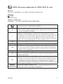
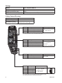
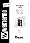
6651-2251
ODW-730-F2
Fibre Optic Modem
Industrial Converter
RS-485 to Fibre Optic Link.
Repeater, line and redundant ring
www.westermo.com
© Westermo Teleindustri AB
User Guide
Legal information
The contents of this document are provided “as is”. Except as required by applicable
law, no warranties of any kind, either express or implied, including, but not limited to,
the implied warranties of merchantability and fitness for a particular purpose, are made
in relation to the accuracy and reliability or contents of this document. Westermo
reserves the right to revise this document or withdraw it at any time without prior
notice.
Under no circumstances shall Westermo be responsible for any loss of data or income
or any special, incidental, and consequential or indirect damages howsoever caused.
More information about Westermo can be found at the following Internet address:
http://www.westermo.com
2
6651-2251
Safety
!
!
!
Before installation:
Read this manual completely and gather all information on the unit. Make sure
that you understand it fully. Check that your application does not exceed the safe
operating specifications for this unit.
This unit should only be installed by qualified personnel.
This unit should be built-in to an apparatus cabinet, or similar, where access is
restricted to service personnel only.
The power supply wiring must be sufficiently fused, and if necessary it must be
possible to disconnect manually from the power supply. Ensure compliance to
national installation regulations.
This unit uses convection cooling. To avoid obstructing the airflow around the unit,
follow the spacing recommendations (see Cooling section).
Before mounting, using or removing this unit:
Prevent access to hazardous voltages by disconnecting the unit from the power
supply.
Warning! Do not open a connected unit. Hazardous voltages may occur within
this unit when connected to a power supply.
Class 1 Laser Product
This unit is designed to meet the Class 1 Laser regulations. However, the user is
warned not to look directly into fibre optical port or any connected fibre.
Care recommendations
Follow the care recommendations below to maintain full operation of the unit and to
fulfil the warranty obligations.
This unit must not be operated with covers or lids removed.
Do not attempt to disassemble the unit. There are no user serviceable parts inside.
Do not drop, knock or shake the unit. Rough handling beyond the specification may cause
damage to internal circuit boards.
Do not use harsh chemicals, cleaning solvents or strong detergents to clean the unit.
Do not paint the unit. Paint can clog the unit and prevent proper operation.
Do not expose the unit to any kind of liquids (rain, beverages, etc).
The unit is not waterproof. Keep the unit within the specified humidity levels.
Do not use or store the unit in dusty, dirty areas. Connectors as well as other
mechanical parts may be damaged.
If the unit is not working properly, contact the place of purchase, nearest Westermo
distributor office, or Westermo Tech support.
Fibre connectors are supplied with plugs to avoid contamination inside the optical port.
The plug should be fitted when no optical fibre is inserted in the connector, e.g. during
storage, service or transportation.
6651-2251
3
Note. Fibre Optic Handling
Fibre optic equipment requires careful handling as the fibre components are very
sensitive to dust and dirt. If the fibre is disconnected from the modem, the protective
plug on the transmitter/receiver must be replaced. The protective plug must be kept on
during transportation. The fibre optic cable must also be protected in the same way.
If this recommendation is not followed, it can jeopardise the warranty.
Cleaning of the optical connectors
In the event of contamination, the optical connectors should be cleaned by using forced
nitrogen and some kind of cleaning stick.
Recommended cleaning fluids:
• Methyl-, ethyl-, isopropyl- or isobutyl-alcohol
• Hexane
• Naphtha
Maintenance
No maintenance is required, as long as the unit is used as intended within the specified
conditions.
Agency approvals and standards compliance
Type
Approval / Compliance
EMC
EN 61000-6-1, Immunity residential environments
EN 61000-6-2, Immunity industrial environments
EN 61000-6-3, Emission residential environments
EN 61000-6-4, Emission industrial environments
EN 55022, Emission IT equipment, class A
EN 55024, Immunity IT equipment
FCC part 15 Class A
EN 50121-4, Railway signalling and telecommunications apparatus
IEC 62236-4, Railway signalling and telecommunications apparatus
Safety
EN 60950-1, IT equipment
ATEX*
EN 60079-0 and EN 60079-15
* Applicable for ODW-730-F2 Ex only
FCC Part 15.105
Notice:
This equipment has been tested and found to comply with the limits for a Class A
digital device, pursuant to Part 15 of the FCC Rules. These limits are designed to provide
reasonable protection against harmful interference when the equipment is operated in a
commercial environment.
This equipment generates, uses, and can radiate radio frequency energy and, if not
installed and used in accordance with the instruction manual, may cause harmful interference to radio communications. Operation of this equipment in a residential area is likely
to cause harmful interference in which case the user will be required to correct the
interference at his own expense.
EN 55022 Notice: This is a class A product. In a domestic environment this product may cause radio interference in which case the user may be required to take adequate measures.
4
6651-2251
ATEX Information (Applicable for ODW-730-F2 Ex only)
General
This unit is intended for use in Zone 2 hazardous location only.
Marking
II 3 G
Ex nA IIC T4 Gc
SPECIAL CONDITION
WARNING – DO NOT SEPARATE WHEN ENERGIZED
Indicate that this unit complies with relevant European standards that are
harmonised with the 94/9/EC Directive (ATEX).
II
3
G
Ex
nA
IIC
T4
Gc
SPECIAL
CONDITION
6651-2251
Equipment group II.
This unit can be installed in all places with an explosive gas atmosphere other
than mines susceptible to firedamp
Equipment category 3.
A category is the classification according to the required level of protection.
This unit ensures the requisite level of protection during normal operation and
is intended for use in areas in which explosive atmosphere caused by gases,
vapours, mists, or dust mixtures are unlikely to occure or, if they do occure, are
likely to do so only infrequently and for a short periode only.
Indicates protection concerning explosive atmospheres caused by gases,
vapours or mists (G).
Indicates that this unit is in conformity with relevant European Ex standard(s).
Type of protection used.
This unit is a non-sparking device "nA" which is constructed to minimize the
risk of occurence of arcs or sparks capable of creating an ignition hazard during
conditions of normal operation.
Gas group, a typical gas i hydrogen.
Temperature class T4 (T4 = 135°C).
This unit is classified in accordance with its maximum surface temperature
(external and internal).
Equipment protection level Gc (EPL Gc).
Equipment for explosive gas atmospheres, having a "enhanced" level of protection, which is not a source of ignition in normal operation and which may have
some additional protection to ensure that it remains inactive as an ignition
source in the case of regular expected occurences. EPL Gc are analogous to the
ATEX Categories (Category 3 G = EPL Gc).
This unit has a special condition of use.
The special condition for safe use contains safety related information that is
necesarry for the correct installation and safe use.
5
Ratings
Power
Ambient temperature
Ingress protection (IP)
Maximum surface temperatur
(12 – 48) VDC; 400 mA
–40ºC ≤ Ta ≤ +60ºC
IP21
135ºC (temperature class T4)
Safety Control Drawing
Degree of protection
Ambient temperature
Installation spacing
IP 21
–40°C to +60°C
Minimum 25 mm above / below
Minimum 10 mm left / right
Direction relative this unit!
Position
1
2
3
Descripton
In & out / Relay contact (NO)
In & out / Relay contact (C)
In & out / Relay contact (NC)
Input / Output values
Uin = 60 VDC max
Iin = 500 mA max
Galvanically isolated via mechanical relay.
See user manual for proven transient protection.
Descripton
In+ (EIA RS-485 A)
In / R– (EIA RS-485 B)
In/out / T+ (EIA RS-485 A)
4
In/out / T– (EIA RS-485 B)
Input / Output values
Umax = ± 5 Vpk
Imax = ± 250 mA
Data rate:
300 bit/s to 1.5 Mbit/s
123
4
Position
1
2
3
Position Descripton
Rx
In / Receive port
Tx
Out / Transmit port
Position Descripton
1
In / Common
2
3
4
In / +Voltage A
In / +Voltage B
In / Common
Output values
Max 0 dBm
Intput values
Uin = (10 – 60) VDC
Iin = 550 mA max
PIn = Max 5.5 W
See section Type tests and environmental conditions in this
user manual for proven transient protection.
6
6651-2251
SPECIAL CONDITION FOR SAFE USE
Ambient temperature:
This unit is designed for use in extreme ambient temperature conditions as follows:
–40 ºC ≤ Ta ≤ +60 ºC
Installation in an apparatus cabinet:
This unit requires installation in an Ex certified apparatus cabinet suitable for the area of use and
providing a degree of protection of at least IP54.
Resistance to impact:
This unit requires installation in an apparatus cabinet where adequate resistance to impact is
provided by the apparatus cabinet. See "Installation in an apparatus cabinet" above for requirements
on the external apparatus cabinet.
Resistance to light:
This unit requires installation in an apparatus cabinet where it is protected from light
(for example daylight or light from luminaires).
See "Installation in an apparatus cabinet" above for requirements on the external apparatus cabinet.
Secureness of plugs:
When this unit is installed in an explosive atmospheres, all connectors must be mechanically secured
to prevent loosening.
Conductor temperature:
When this unit is installed in locations with high ambient temperature, special precautions shall be
taken upon the choice of external conductors and the temperature rating of the conductor(s).
Directive 94/9/EC alongside with other directives:
Directive 2004/108/EC (EMC) applies and to assure a safe performance of this unit under the scope
of Directive 94/9/EC, refer to the electromagnetic immunity level specified under "Type tests and
environmental conditions" in this manual.
Standards and date of compliance
EN 60079-0 and EN 60079-15
2010-12-17
6651-2251
7
Declaration of Conformity
Westermo Teleindustri AB
Declaration of conformity
The manufacturer
Westermo Teleindustri AB
SE-640 40 Stora Sundby, Sweden
Herewith declares that the product(s)
Type of product
Model
Art no
Industrial fiberoptic repeaters/media
converters
ODW-700 series
3651-07xx
ODW-700EX series
3651-37xx
is in conformity with the following EC directive(s).
No
Short name
2004/108/EC
94/9/EC1
Electromagnetic Compatibility (EMC)
Equipment Explosive Atmospheres (ATEX)
References of standards applied for this EC declaration of conformity.
No
EN 61000-6-1
Title
Electromagnetic compatibility – Immunity residential environments
Issue
2007
EN 61000-6-2
Electromagnetic compatibility – Immunity industrial environments
2005
EN 61000-6-3
Electromagnetic compatibility – Emission residential environments
2007
EN 61000-6-4
2007
EN 55022
Electromagnetic compatibility – Emission for industrial
environments
Information technology equipment - Emission
EN 55024
Information technology equipment - Immunity
EN 50121-4
Railway applications – Electromagnetic compatibility – Emission
and immunity of the signalling and telecommunications apparatus
Explosive atmospheres – Equipment – General requirements
1998 + A1:2001 +
A2:2003
2006
EN 60079-0
EN 60079-15
Electrical apparatus for explosive gas atmospheres –
Construction, test and marking of type of protection “n” electrical
apparatus
The last two digits of the year in which the CE marking was affixed:
2006 + A1:2007
2009
2005
11
Pierre Öberg
Technical Manager
15th June 2011
1
8
Applicable for ODW-700EX series only.
Postadress/Postal address
Tel.
Telefax
Postgiro
Bankgiro
Org.nr/
Corp. identity number
Registered office
S-640 40 Stora Sundby
Sweden
016-428000
Int+46 16428000
016-428001
Int+46 16428001
52 72 79-4
5671-5550
556361-2604
Eskilstuna
6651-2251
Type tests and environmental conditions
Electromagnetic Compatibility
Phenomena
Test
ESD
EN 61000-4-2
RF field AM modulated
IEC 61000-4-3
RF field 900 MHz
Fast transient
ENV 50204
EN 61000-4-4
Surge
EN 61000-4-5
RF conducted
EN 61000-4-6
Pulse Magnetic field
Voltage dips
and interruption
EN 61000-4-9
EN 61000-4-11
Mains freq. 50 Hz
Mains freq. 50 Hz
Radiated emission
EN 61000-4-16
SS 436 15 03
EN 55022
FCC part 15
EN 55022
FCC part 15
EN 55022
EN 60950
Conducted emission
Dielectric strength
Environmental
Temperature
Shock
Packaging
Enclosure, ODW-730-F2
Enclosure,
ODW-730-F2 EX
Dimension W x H x D
Weight
Degree of protection
Cooling
Mounting
6651-2251
Enclosure
Signal ports
Power ports
Signal ports unbalanced
Signal ports balanced
Power ports
Signal ports
Power ports
Enclosure
AC power ports
Signal ports
Signal ports
Enclosure
AC power ports
AC power ports
DC power ports
Signal port to all other
isolated ports
Power port to other
isolated ports
IEC 60068-2-6
Operating
Storage & Transport
Maximum surface
temperature
Operating
Storage & Transport
Operating
Operating
Operating
IEC 60068-2-27
Operating
UL 94
PC / ABS
Cabelec 6141
Humidity
Altitude
Service life
Vibration
Description
Enclosure contact
Enclosure air
Enclosure
IEC 529
Enclosure
Level
± 6 kV
± 8 kV
10 V/m 80% AM (1 kHz), 80 – 800 MHz
20 V/m 80% AM (1 kHz), 800 – 1000 MHz
20 V/m 80% AM (1 kHz), 1400 – 2700 MHz
20 V/m pulse modulated 200 Hz, 900 ± 5 MHz
± 2 kV
± 2 kV
± 2 kV line to earth, ± 2 kV line to line
± 2 kV line to earth, ± 1 kV line to line
± 2 kV line to earth, ± 2 kV line to line
10 V 80% AM (1 kHz), 0.15 – 80 MHz
10 V 80% AM (1 kHz), 0.15 – 80 MHz
300 A/m, 6.4 / 16 µs pulse
10 & 5 000 ms, interruption
200 ms, 40% residual voltage
500 ms, 70% residual voltage
100 V 50 Hz line to earth
250 V 50 Hz line to line
Class B
Class A
Class B
Class B
Class A
2 kVrms 50 Hz 1min
3 kVrms 50 Hz 1min
2 kVrms 50 Hz 1min (@ rated power < 60V)
–40 to +60°C
–40 to +70°C
135ºC (temperature class T4)
5 to 95% relative humidity
5 to 95% relative humidity
2 000 m / 70 kPa
10 year
7.5 mm, 5 – 8 Hz
2 g, 8 – 500 Hz
15 g, 11 ms
Flammability class V-1
35 x 121 x 119 mm
0.26 kg
IP 21
Convection
Horizontal on 35 mm DIN-rail
9
Functional description
Switches
LED’s
POWER
+VA
+VB
COM
O
V
P
Internal
Electronics
COM
+5V
0V
O
V
P
STATUS
NO
C
NC
ODW-730
+5V
RS -485
O
C
P
T/R T/R+
RR+
0V
CH 1
OVP Over Voltage Protection
OCP Over Current Protection
SFP
Fibre transceiver
TX
RX
SFP
Fibre transceiver
TX
RX
CH 2
Converter serial interface – optical fibre
ODW-730 is a fibre optic modem that converts between electrical RS-485 and a fibre
optical link.
ODW-730 can also be used to convert from RS-485 to RS-232 by using a ODW-730 in
the same link as ODW-720.
Repeater – optical fibre links
ODW-730 is a fibre optic repeater that repeats received data from one fibre link out to
the other link. This is useful e.g. for long distance communication, where electromagnetic
interference may occur or when isolation of the electrical network is needed. The maximum optical fibre distance depends on selected fibre transceiver and fibre type. Distances
up to 80 km (50 miles) are available.
10
6651-2251
Interface specifications
Power
Rated voltage
Operating voltage
Rated current
Rated frequency
Inrush current I²t
Startup current*
Polarity
Redundant power input
Isolation to
Connection
Connector size
Shielded cable
ODW-730-F2:
12 to 48 VDC and 24 VAC
ODW-730-F2 Ex: 12 to 48 VDC
ODW-730-F2:
10 to 60 VDC and 20 to 30 VAC
ODW-730-F2 Ex: 10 to 60 VDC
400 mA @ 12 V
250 mA @ 24 V
100 mA @ 48 V
ODW-730-F2:
DC and 48 to 62 Hz
ODW-730-F2 Ex: DC
0.2 A²s
1.0 Apeak
Reverse polarity protected
Yes
RS-485 and Status port
Detachable screw terminal
0.2 – 2.5 mm² (AWG 24 – 12)
Not required
* External supply current capability for proper startup
Status
Port type
Rated voltage
Operating voltage
Contact rating
Contact resistance
Isolation to
Connection
Connector size
Shielded cable
6651-2251
Signal relay, changeover contacts
Up to 48 VDC
Up to 60 VDC
500 mA @ 48 VDC
< 50 mW
RS-485 and Power port
Detachable screw terminal
0.2 – 2.5 mm² (AWG 24 – 12)
Not required
11
RS-422/485
Electrical specification
Data rate
Data format
Protocol
Retiming
Turning time
(2-wire RS-485)
Transmission range
Settings
Protection
Isolation to
Connection
Connector size
Shielded cable
EIA RS-485, 2-wire or 4-wire twisted pair
300 bit/s – 1.5 Mbit/s
9 – 12 bits
Start-bit followed by 8-11 bits
Yes
One tbit
tbit = 1 / Baud rate (Baud rate in bit/s)
< 1200 m, depending on data rate and cable type (EIA RS-485)
120 W termination and failsafe biasing 680 W
Installation Fault Tolerant (up to ±60 V)
Status and Power port
Detachable screw terminal
0.2 – 2.5 mm² (AWG 24 – 12)
Not required
Optical Power Budget
The allowed link length is calculated from the optical power budget (OPB), the available optical
power for a fibre-optic link, and the attenuation of the fibre, comprising losses due to in-line
connectors, splices, optical switches and a margin for link ageing (typical 1.5 dB for 1300 nm).
The worst-case optical power budget (OPB) in dB for a fibre-optic link is determined by the difference between the transmitter’s output optical power (min) and the receiver input sensitivity (max).
FX (Fibre)
Fibre connector
Fibre type
SM-LC80
LC duplex
Singlemode
9/125 mm
SM-LC40
LC duplex
Singlemode
9/125 mm
SM-LC15
LC duplex
Singlemode
9/125 mm
Wavelength
Transmitter
Output optical power min/max
Receiver
Input sensitivity, max
Receiver
Input optical power, max
Optical power budget,
worst-case
Transceiver type
1550 nm
–5/0 dBm**
1310 nm
–5/0 dBm**
1310 nm
–15/–8 dBm**
MM-LC2
LC duplex
Multimode,
62.5/125 and
50/125 mm
1310 nm
–20/–14 dBm*
–34 dBm
–34 dBm
–33 dBm
–31 dBm
0 dBm***
0 dBm***
0 dBm
–8 dBm
29 dB
29 dB
18 dB
11 dB
Laser class
*
**
***
12
Small Form Factor Pluggable (SFP)
Multi-Sourcing Agreement (MSA) compliant
Class 1, IEC 825-1 Accessible Emission Limit (AEL)
Output power is power coupled into a 62.5/125 mm multimode fibre
Output power is power coupled into a 9/125 mm singlemode fibre
The optical power should be reduced by at least 5 dB (SM-LC80 and Bi-di LC-60) or 3dB (SM-LC-40
and Bi-di LC-40) between the optical output and input.
6651-2251
FX (Fibre)
Fibre connector
Fibre type
Wavelength nm, connector 1
Wavelength nm, connector 2
Transmitter
Output optical power min/max
Receiver
Input sensitivity, max
Receiver
Input optical power, max
Optical power budget,
worst-case
Bit error rate (BER)
Transceiver type
Laser class
*
**
***
Bi-di
LC-40
LC Simplex
Singlemode
9/125 μm
Bi-di
LC-20
LC Simplex
Singlemode
9/125 μm
Tx 1310, rx 1550
Tx 1550, rx 1310
–8/0 dBm**
Tx1310, rx 1550
TX 1550, rx 1310
–14/8 dBm**
Bi-di
MM LC-2
LC Simplex
Multimode
62.5/125 and
50/125 μm
Tx 1310, rx 1550
Tx 1550, rx 1310
–10/–0 dBm*
–32 dBm
–31 dBm
–27 dBm
–3 dBm***
0 dBm
0 dBm
24 dB
17 dB
17 dB
< 1 x 10⁻¹⁰
< 1 x 10⁻¹⁰
< 1 x 10⁻¹⁰
Output power is power coupled into a 62.5/125 mm multimode fibre
Output power is power coupled into a 9/125 mm singlemode fibre
The optical power should be reduced by at least 5 dB (SM-LC80 and Bi-di LC-60) or 3dB (SM-LC-40
and Bi-di LC-40) between the optical output and input.
6651-2251
13
Location of Interface ports, LED’s and DIP-switches
ODW-730-F2
LED Indicators(for details see page 15)
DIP-switches accessible under lid
(for details see page 16–18)
Status
screw terminal
Position
1
2
3
Description
Contact with C when fibre optical
links are in operation
Common
Open (no contact with C)
when fibre optical links are
not in operation
Product
marking
NO
C
NC
RS-422/485
screw terminal
FX(Fibre)
(for details
see page 12–13)
Position
Direction*
Description
Product
marking
1
In
R+ (EIA RS-485 A’)
2
In
R– (EIA RS-485 B’)
R–
3
In/Out
T+ (EIA RS-485 A)
T/R+
4
In/Out
T– (EIA RS-485 B)
T/R–
R+
Power
screw terminal
Position
Direction*
1
2
3
4
In
In
In
In
Description
Common voltage
Voltage A
Voltage B
Common voltage
Product
marking
COM
+VA
+VB
COM
* Direction relative this unit
14
6651-2251
LED indicators
LED
Status
Description
PWR
ON
Power is on.
OFF
Power is off.
ON
Focal point
OFF
Redundant ring member or multidrop
unit.
ON
Fiber link to other unit has been established at CH 2.
Flashing
Optical power detected but link to other
unit has not been established at CH 2.
OFF
No optical power detected and no link
to other unit has been established at
CH 2.
ON
Fiber link to other unit has been established at CH 1.
Flashing
Optical power detected but link to other
unit has not been established at CH 1.
OFF
No optical power detected and no link
to other unit has been established at
CH 1.
Flash
Data received on the electrical interface
and transmitted out on the optical interface.
OFF
No data received on the electrical interface.
Flash
Data received on the optical interface
and transmitted out on the electrical
interface.
OFF
No data received on the optical interface.
ON
Remote fibre link failure.
A fibre link is out of operation at any
other unit than this one.
Flashing
Hardware error or invalid configuration.
ON
Local fibre link failure.
A fibre link is out of operation at this
unit.
Flashing
Hardware error or invalid configuration.
Power
FP
CH 2
Channel 2 link status
CH 1
Channel 1 link status
TD
RD
FL R
Failure link remote
FL L
Failure link local
Note: During power up, all LED’s will turn on for about 1 second.
6651-2251
15
! DIP-switch settings
Before DIP-switch settings:
Prevent damage to internal electronics from electrostatic discharges (ESD) by
discharging your body to a grounding point (e.g. use of wrist strap)
Note: Disconnect power before DIP-switch settings.
S1
S2
S3
S1 DIP-switch, asynchronous mode speed selection
ON
ON
1 2 34 56 78
300 bit/s
ON
1 2 34 56 78
ON
57.6 kbit/s
ON
1 2 34 56 78
1200 bit/s
115.2 kbit/s
ON
1 2 34 56 78
2400 bit/s
125 kbit/s
ON
1 2 34 56 78
4800 bit/s
187.5 kbit/s
ON
9600 bit/s
230.4 kbit/s
ON
19.2 kbit/s
1 2 34 56 78
ON
1 2 34 56 78
ON
1 2 34 56 78
ON
1 2 34 56 78
ON
1 2 34 56 78
1 2 34 56 78
ON
1 2 34 56 78
ON
1 2 34 56 78
1 2 34 56 78
ON
1 2 34 56 78
ON
1.0 Mbit/s
ON
1 2 34 56 78
ON
1 2 34 56 78
250 kbit/s
1 2 34 56 78
1.5 Mbit/s
9 bits data
format
10 bits data
format
11 bits data
format
12 bits data
format
ON
1 2 34 56 78
38.4 kbit/s
1 2 34 56 78
500 kbit/s
Supervision table when selecting data format
Start bit
…
…
…
7 bit
…
…
…
8 bit
…
16
10
…
…
…
…
…
…
…
…
…
…
10
10
…
9
…
…
…
2 stop bit
Number of bit
…
…
Parity
1 stop bit
…
…
…
…
11
11
…
11
12
6651-2251
S1 DIP-switch, synchronous mode time frame selection
ON
ON
1 2 34 56 78
1.6 ms
1 2 34 56 78
ON
ON
13 μs
1 2 34 56 78
ON
1 2 34 56 78
416 μs
1 2 34 56 78
ON
ON
8.6 μs
1 2 34 56 78
ON
1 2 34 56 78
208 μs
1 2 34 56 78
ON
104 μs
1 2 34 56 78
ON
1 μs
ON
4.3 μs
1 2 34 56 78
ON
1 2 34 56 78
2 μs
500 ns
ON
4 μs
1 2 34 56 78
300 ns
ON
1 2 34 56 78
52 μs
1 2 34 56 78
ON
2.6 μs
ON
1 2 34 56 78
26 μs
1 2 34 56 78
2.1 μs
S1 DIP-switch / Description V/Y mode
ON
ON
V-mode
Y-mode
1 2 34 56 78
1 2 34 56 78
If only fibre channel 1 is used or
if redundant ring focal point
OR
OR
channel 2
channel 1
OR
channel 2
channel 1
RS-485
RS-485
If both fibre channels 1 and 2 are used
and not redundant ring focal point
OR
channel 2
channel 1
RS-485
If only fibre channel 2 is used
channel 2
channel 1
RS-485
For applications that only require half duplex communication it is recommended to use
Y-mode. Please see the ODW-730 Management Guide for further details.
6651-2251
17
S2 DIP-switch
ON
1 2 34 56 78
ON
1 2 34 56 78
ON
RS-232
2-wire
1 2 34 56 78
RS-485
4-wire
1 2 34 56 78
Use secondary data channel.
ON
ON
ON
Multidrop mode.
1 2 34 56 78
1 2 34 56 78
ON
ON
Redundant ring mode.
1 2 34 56 78
ON
1 2 34 56 78
ON
1 2 34 56 78
1 2 34 56 78
Multidrop mid unit or
Redundant ring member.
Multidrop end unit. Redundant ring
focal point.
ON
1 2 34 56 78
Single channel system redundant
ring. E.g. only the primary or
secondary channel is used.
Dual channel system redundant ring.
E.g. both the primary and secondary
channel are used simultaneously.
Set status port on both local fibre
link (FL L) and remote fibre link
(FL R) errors.
Set status port on local fibre link
(FL L) error only.
ON
S2:7 has no function
1 2 34 56 78
ON
ON
Use primary data channel.
1 2 34 56 78
Always OFF
1 2 34 56 78
S3 DIP-switch
ON
ON
No termination and fail-safe
1 2 34
Termination with fail-safe (2-wire)
1 2 34
ON
Termination with fail-safe (4-wire)
1 2 34
Factory default
ON
1 2 34 56 78
18
ON
S1
1 2 34 56 78
S2
6651-2251
RS-485 termination at system level
The system should be installed in according to the RS-485 specification. A system should
always form a bus structure where the termination is at the end points of the bus.
See diagrams for details of how this is done with RS-485 2-wire and 4-wire.
R+
R–
T+
T–
ODW-730 Series
R– R+ T– T+ R– R+ T– T+
R– R+ T– T+
=Termination
Slave unit
Slave unit
Slave unit
T/R+
T/R–
Max 0.3 metre
ODW-730 Series
T/R– T/R+
T/R– T/R+
T/R– T/R+
=Termination
Slave unit
6651-2251
Slave unit
Slave unit
19
About the interfaces
Power terminal
The power terminal has two independent inputs, +VA and +VB, allowing redundancy
should either fail. The ODW-730 power supply is galvanically isolated from all other
internal electronics.
Optical fibre interfaces
ODW-730 uses Small From Factor Pluggable (SFP) transceivers that are in compliance
with the Multi-Sourcing Agreement (MSA). This means that a wide range of different fibre
tranceivers and connectors can be used.
RS-485 interface
A 4 position detachable screw terminal that can handle full duplex data rates up to
1.5 Mbit/s and can be set to either 2- or 4-wire RS-485 system.
When 4-wire RS-485 is selected, the terminals T/R+ and T/R– will always be set to
transmit and terminals R+ and R– will always receive data.
Manchester coded protocol can be tranferred with Synchroous mode.
Status port
The status port connects to an internal relay wich may be used to trigger an external
alarm if a fault condition occurs. During normal operation pins 1 and 2 are in contact
with each other, and pins 2 and 3 are isolated. During an optical link failure, or power
failure, pins 1 and 2 are isolated, and pins 2 and 3 are in contact with each other.
Optical link failures can be classified in to two categories, local or remote, as indicated by
the FL L and FL R LED’s. A local link failure is when an optical link is down at this
particular unit. A remote link failure is when an optical link is down at some other unit.
From the factory, the status port is set to trigger on both types of link failures.
However, by setting DIP-switch S2:6 to the ON position, the status port will only
trigger when a local link failure has occured.
20
6651-2251
Mounting
This unit should be mounted on 35 mm DIN-rail, which is
horizontally mounted inside an apparatus cabinet, or similar.
Snap on mounting, see figure.
CLICK!
CLICK!
Cooling
This unit uses convection cooling. To avoid obstructing the airflow around the unit, use the following spacing rules. Minimum
spacing 25 mm (1.0 inch) above /below and 10 mm (0.4 inches)
left /right the unit. Spacing is recommended for the use of unit
in full operating temperature range and service life.
10 mm *
(0.4 inches)
* S pacing (left/right) recommended for
full operating temperature range
25 mm
25 mm
Removal
Press down the black support at the top of the unit. See figure.
6651-2251
21
Referring documents
For detailed information on how to configure the ODW-730-F2 for different applications.
Type
Management Guide
22
Description
Management Guide ODW-730-F2
Document number
6651-2255
6651-2251
Westermo Teleindustri AB • SE-640 40 Stora Sundby, Sweden
Phone +46 16 42 80 00 Fax +46 16 42 80 01
E-mail: [email protected]
Westermo Web site: www.westermo.com
United Kingdom
Westermo Data Communications Ltd
Talisman Business Centre • Duncan Road
Park Gate, Southampton • SO31 7GA
Phone: +44(0)1489 580‑585 • Fax.:+44(0)1489 580586
E-Mail: [email protected]
Germany
Westermo Data Communications GmbH
Goethestraße 67, 68753 Waghäusel
Tel.: +49(0)7254-95400-0 • Fax.:+49(0)7254-95400-9
E-Mail: [email protected]
France
Westermo Data Communications S.A.R.L.
9 Chemin de Chilly 91160 CHAMPLAN
Tél : +33 1 69 10 21 00 • Fax : +33 1 69 10 21 01
E-mail : [email protected]
Singapore
Westermo Data Communications Pte Ltd
2 Soon Wing Road #08-05
Soon Wing Industrial Building
Singapore 347893
Phone +65 6743 9801 • Fax +65 6745 0670
E-Mail: [email protected]
North America
Westermo Data Communications
939 N. Plum Grove Road, Suite F
Schaumburg
Chicago
Phone: +1 847 619 6068
Fax: +1 847 619 66 74
E-mail: [email protected]
Taiwan
Westermo Data Communications Co
F2, No. 188, Pao-Chiao Rd.
Shing-Tien City
Taipei 23145
Phone:+886 2 8911 1710
E-mail: [email protected]
Westermo Teleindustri AB have distributors in several countries, contact us for further information.
REV.A 6651-2251 2011-04 Westermo Teleindustri AB, Sweden – A Beijer Electronics Group Company
Sales Units
Sweden
Westermo Data Communications AB
Svalgången 1
SE-724 81 Västerås
Phone: +46 (0)21 548 08 00 • Fax: +46 (0)21 35 18 50
E-Mail: [email protected]