1
EV80Cl96KB
Evaluation Board
User’s Manual
(bier
Number
270738-()O]
EV80C196KB Microcontroller Evaluation Board
Release 001
February 20,1989
Copyright 1989, Intel Corporation
Intel Corporation makes no warranty of any kind with regard to this material, including, but not limited
to, the implied warranties of merchantability and fitness for a particular purpose. Intel Corporation
assumes no responsibitlity for any errors that may appear in this document. Intel Corporation makes
no commitment to update nor to keep current the information contained in this document.
Intel Corporation assumes no responsibility for the use of any circuitry other than circuitry embodied
in an Intel product. No other circuit patents licenses are implied.
Intel software products are copyrighted by and shall remain the property of Intel Corporation. Use,
duplication, or disclosure is subject to restrictions stated in Intel’s Software License Agreement, or in
the case of software delivered to the U.S. government, in accordance with the software license
agreement as defined in FAR 52.227-7013.
No part of this document may be copied or reproduced in any form or by any means without prior
written consent of Intel Corporation.
Intel Corporation retains the right to make changes to these specifications at any time, without notice.
Contact your local sales office to obtain the latest specifications before placing your order.
The following are trademarks of Intel Corporation and its affiliates and may be used only to identify
Intel products:
376, Above, ActionMedia, BITBUS, Code Builder, DeskWare, Digital Studio, DVI, EtherExpress,
ETOX, ExCA, FaxBACK, Grand Challenge, i, i287, i386, i387, i486, i487, i750, i860, i960, ICE,
itBX, Inboard, Intel, lnte1287, lntel386, lntel387, lntel486, lntel487, intel inside., Intellec, iPSC,
iRMX, iSBC, ISBX, iWarp, LANprint, LANSelect, LANShell, LANSight, LANSpace, LANSpool,
MAPNET, Matched, MCS, Media Mail, NetPort, NetSentry, OpenNET, Paragon, PR0750,
ProSolver, READY-LAN, Reference Point, RMX/80, SatisFAXtion, Snapln 386, Storage Broker,
SugarCube, The Computer Inside., TokenExpress, Visual Edge, and WYPIWYF.
and the combinations of CCE,ICS, iRMX, ISBC, ISBX, iSXM, MCS, or UPI and a numerical suffix.
MDS is an ordering code only and is not used as a product name or trademark. MDS is a
registered trademark of Mohawk Data Sciences Corportation.
CHMOS and HMOS are patented processes of Intel Corp.
Intel Corporation and Intel’s FASTPATH are not affiliated with Kinetics, a division of Excelan,
Inc. or its FASTPATH trademark or products.
RBMis a registered trademark and AT is a trademark of International Business Machines, Inc.
Microsoft MS, MS-DOS, and XENIX are registered trademarks and Multiplan is a trademark
of Microsoft Corporation.
Addional copies of this manual or other Intel Literature may be obtained from:
Intel Corporation, Literature Sales
P.O. Box 7641
Mt. Prospect, IL 60056-7641
CONTENTS
SECTION Description ...... .... ............. ............ ...
PAGE
INTRODUCTION ........................................................................................
GETTING STARTED WITH THE EV80Cl96KB ........................................
Powering the Board ........................................................................
Connecting to your PC ....................................................................
Starting the Host Software ..............................................................
HARDWARE OVERVIEW OF THE EV80Cl96KB BOARD ......................
Block Diagram of the EV80C196KB Board.. ....................................
Processor ........................................................................................
Memory‘ ............................................................................................
Host Interface ..................................................................................
Digital I/O ........................................................................................
Analog Inputs ..................................................................................
Decoding ........................................................................................
Configuration Jumper Locations (Figure 3a) ..................................
Memory Configuration Jumper Locations (Figure 3b) ....................
Expansion Ports, Connectors and LEDs Locations (Figure 4) ........
Host Serial Connector (Figure 5) ....................................................
8OCl96KB Serial Port Connector (Figure 6) ..................................
Analog Input Connector (Figure 7) ..................................................
I/O Expansion Connector (Figure 8) ................................................
Memory-l/O Expansion Connector (Figure 9) ..................................
Power Supply Connector (Figure 10) ..............................................
25pin to g-pin Adapter (Figure 11) ................................................
INTRODUCTION TO iRISM-iECM96 SOFTWARE.. ..................................
Features ..........................................................................................
Restrictions ......................................................................................
OVERVIEW ................................................................................................
Embedded Controller Monitor.. ........................................................
USER INTERFACE ....................................................................................
Background Information ..................................................................
Initiating and Terminating iECM-96 ................................................
Default Base Commands ................................................................
9
9
9
9
9
10
10
30
10
11
11
11
12
14
15
16
17
17
18
18
19
19
20
21
21
22
23
23
24
24
25
28
FILE OPERATIONS ....................................................................................
Loading and Saving Object Code ....................................................
Other File Operations.. ......................................................................
PROGRAM CONTROL ................................................................................
Resetting the Target ........................................................................
Breakpoints ......................................................................................
Program Execution ..........................................................................
Program Stepping ............................................................................
DISPLAYING AND MODIFYING PROGRAM VARIABLES ........................
Supported Data Types ......................................................................
. BYTE Commands ............................................................................
WORD Commands ..........................................................................
DWORD Commands ........................................................................
REAL Commands ............................................................................
STACK Commands ..........................................................................
STRING Commands ........................................................................
Processor Variables ..........................................................................
ASSEMBLY AND DISASSEMBLY ..............................................................
Single Line Assembly Commands ....................................................
Disassembly Commands ..................................................................
SYMBOL OPERATIONS ............................................................................
RISM ..........................................................................................................
RISM Variables ................................................................................
RISM Structure .................................................................................
Receiving Data from the Host ..........................................................
Sending Data to the Host ..................................................................
RISM Commands ..............................................................................
29
29
30
32
32
32
33
35
37
37
38
39
40
41
42
42
43
44
44
45
46
47
47
48
48
48
49
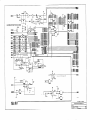
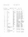
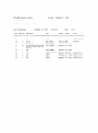
Schematics and Parts List ...... ................... .........~.......~..................~...... Appendix A
Specific iRlSM Information -..~.............~................................~..............0.. Appendix B
..... ........... .. .... ... .......-....*.........a Appendix C
Listing of IRISM-196KB a.*.e..**..*...........*..
Appendix D
Timing Analysis .*-.................*..........e....... ..... ............ ..~........~....~.....~......~
Appendix E
Programmable Logic Equations ..........~...~....~.........~...........~.....~.........~..
Appendix F
Standard Memory-l/O Connector .....~......~................................~~.......~..~
...O.....................*s..*.............eo...Appendix G
Sample Session *“o...~~..~.....~..~.......e...~.*~.
-8-
EV80C196KB Microcontroller Evaluation Board User’s Manual
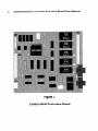
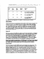
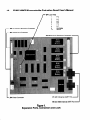
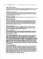
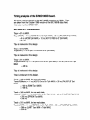
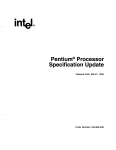
Figure 1.
EV8OCl96KB Evaluation Board
EV80C196KB Microcontroller Evaluation Board User’s Manual -90
INTRODUCTION
The EV80C196KB is a next-generation version of the EV80C196KA. The major
changes are the use of a standard memory expansion bus compatible with the
EV80C51 FB and EV80C186 boards, and the removal of the card edge bus. Also,
the HOLD/HLDA feature of the 8OC196KB is supported. The EV80C196KB is designed to be a software evaluation tool for the ROMless 8OC196KB 16-bit microcontroller. As such, ports 3 and 4 are not available for use as I/O ports unless offboard
latches/buffers and decoding logic are used. All unreserved functions of the
80C196KB are available to you except for the Non-Maskable Interrupt (NMI), the
TRAP instruction, and 512 bytes of address space. The Chip Configuration Byte is
also used by the monitor, but most of its functions are provided by external logic.
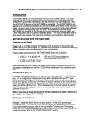
GETTING STARTED WITH THE EV80C396KB
Powering up the Board
Power (+5, +/-12 Volts) must be connected to JP4 as shown on the board’s silkscreen next to JP4 and in figure 10. Included with the board is a packet containing a
Molex connector and crimp terminals for your convenience.
Power supply requirements for the EV80C196KB board are as follows:
+ 5 VDC +I- 5 % @ 280 mA
+12VDC+/-20%@
-12VDC+/-20%@
(150 mA if LED’s are disabled by
removing jumper shunt El 6)
15mA
15mA
Upon power-up (or after a reset) the board goes through initializations and a shifting-pattern is displayed on the Port 1 LEDs when initialization has completed properly.
Connecting to your PC
Once you have applied power to the board, you need to connect Pl to a PC serial
port. Pl is configured to interface pin-to-pin with a standard nine-pin AT@)-type
serial connector (see figure 5 for pinout). Make certain that you use a cable providing all nine signals, as they are all needed for proper operation of the host interface.
When you have connected the cable, you may observe that the 8OC196KB is held in
reset, and all the LEDs turn on. This is because one of the host signals is used to
reset the part, and the signal’is often in a reset condition prior to invoking the host
software on your PC.
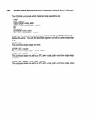
Note: if you have a 25pin serial port it will be necessary to make a 2%pin to 9pin adaptor (see figure 11 for details).
Starting the Host Software
After the you have made both connections to the board, you can invoke the host
interface. Install the disk in drive A of your system. At the DOS prompt type
“A:ECM96”eCR>. Your PC should eventually display the iECM-96 monitor screen.
If you have problems please refer to the sub-section “Initiating and Terminating
iECM-96” in the “USER INTERFACE” section of this manual. For further details on
using the monitor, refer to the “USER INTERFACE” section.
-IO-
EV80C196KB Microcontroller Evaluation Board User’s Manual
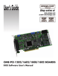
HARDWARE OVERVIEW OF THE EV80C196KB BOARD
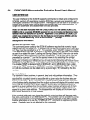
The EV80C196KB Microcontroller Evaluation board is delivered with an 8OC196KB,
8 K-words and 8 K-bytes of user code/data memory, a UART for host communications and analog-input filtering with a precision voltage reference. Also included is
programmable chip-select, bus-width and wait-state-counter logic which allows you
to custom tailor the board to look like your own system. The board’s physical dimensions are 6 l/2” x 7 3/4” with an overall height of 3W. There are six main sections
to the EV80C196KB board: Processor, Memory, Host Interface, Digital I/O, Analog
Inputs and Decoding.
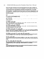
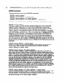
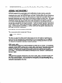
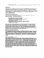
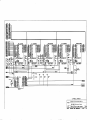
Block Diagram of the 80C196KB Board
Figure 2.
Processor
The Intel@)80C196KB is a 16-bit embedded microcontroller. Being a member of the
MCW-96 family, the 8OC196KB uses the same powerful instruction set and the
same architecture as the existing MCS-96 products. The 8OC196KB is an enhanced
CMOS version of the 8097BH. Its enhancements include up/down and capture
modes on Timer2, multiplyin speeds almost 3 times as fast, overall execution
nearly twice as fast, Hold/Ho9d Acknowledge logic, and power-down and idle modes
to save power. For more information, please refer to the 1989 “16-Bit Embedded
Controller Handbook,” Intel Corporation order number 270646-001 and the
8OC196KB Datasheet order number 270634-001.
Memory
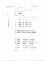
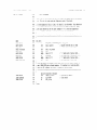
There are five 28-pin memory sockets provided on the EV80C196KB board: Ul , U6,
U8, U13 and U14. The sockets are designed to support byte-wide, JEDEC-pinout,
memory devices of various types and sizes, i.e. 8K x 8 SRAM or 16K x 8 EPROM.
Ul and U8, U6 and U13 are connected as two 16-bit memory banks and U14 is
connected as an 8-bit memory bank.
EV80C196KB Microcontroller Evaluation Board User’s Manual
Bank
No.
Even
Bytes
I.C.
Odd
Bytes
I.C.
Enable
Signal
0
U8
Ul
CEO
8K x 16-bit Monitor EPROM
from 0-FFH and 1DOO-1DFFH
1
u13
U6
CEi
8K x 16-bit ROMsim/RAM
from 2000H-5FFFH
2
u14
u14
CE2
8K x 8-bit ROMsim/RAM
from 6000H-7FFFH
Memory
Type
See appendix B and appendix C for details on reserved areas of memory.
,
Host Interface
The PC host interface is accomplished with the 82510 UART (U20) connected to Pl
via RS-232 drivers. The UART resides in the address range 1EOOH- 1EFFH.
Therefore, register 0 in the UART would be at address 1EOOHof the 8OC196KB,
reg. 1 would be at 1EOl H, reg. 2 would be at 1E02H, etc. up to reg. 7 at 1E07H.
The registers will repeat again with reg. 0 at 1E08H due to the limited decoding
granularity of the EPLD. Pin 12 of the UART, OUTl#, is used to tell the PC host
when the 80C196KB is executing user code by a true level on the Ring Indicator
input of the host serial port.
Digital I/O
With the exception of the NMI input, which is used by the Host Interface, all Digital I/
0 functions of the 8OC196KB are available to you. There are eight LEDs on-board
along with buffer/drivers which allow you to quickly observe the state of Port 1,
HSO.0 and Port 2.5/PWM (see figure 4 or the schematics in appendix A for location). The TxD and RxD pins of the 80C196KB (Port 2.0 and Port 2.1) are connected to RS-232 buffer/drivers, which are connected to P2. All of the I/O signals
are available on JP2 (see figure 8 or the schematics in appendix A for pinout).
Note: because RxD is connected to an RS-232 receiver (U19 pin 3) any attempt
to use it as a digital input will result in a contention. If you would like to use it
as a digital input, remove jumper shunt El9 to disconnect the receiver.
Analog Inputs
The Port 0 inputs of the 80C196KB double as both digital and analog inputs. The
EV80C196KB board includes circuitry to make the analog inputs easier to use. A
precision voltage source for Vref is provided on board (U3 and U4) which can be
carefully adjusted by trimming RPl . Also, jumper shunt E4 allows Vref to be connected to Vcc instead of the output of U3. By removing E4 entirely, an off board
reference can be connected to JPl . By removing jumper shunt E2, ANGND can be
isolated from Vss. Protective clamping diodes are installed on each channel. RC
networks are provided in sockets (to ailow you to change the input impedance to
match your application) on all of the analog input channels. If Port 0 is to be used
-1 I-
-729
EV80C196KB Microcontroller Evaluation Board User’s Manual
as a digital input, it is recommended that the capacitors be removed, and the resistors replaced with wires. For additional connection information refer to figure 7 or
the schematics in appendix A. The ground and power planes beneath the analog
circuitry (Dl , D2, R3, C2, U3, U4, JPI and the analog connections on the
80Cl96KB) are isolated from the digital power and ground planes of the board to
keep noise from the analog inputs.
Decoding
The decoding logic on the EWOCl96KB board serves three purposes; to provide
Chip-Enable signals to memory and peripheral devices, to select the buswidth for
the device(s) being accessed and to provide wait-states for slow devices. This
section is provided in case you need to modify the memory configuration of the
EV80Cl96KB board. It is not necessary to understand this section for normal usage
of the board.
The heart of the decoding logic is U12, a 24-pin 5AC312 Intel EPLD or a C22VlO
programmable logic array which is socketed to allow easy changes. For the sake of
convenience it will be referred to as “the EPLD” throughout this text. The EPLD
uses latched addresses A8-Al5 along with CLKOUT, HLDA#, RESET# and STALE
(STretched ALE) from the 8OCl96KB as decode inputs.
There are 4 enable outputs from the EPLD, all of which are low-level true, however
only one should be true at a time to avoid bus contention. They are decoded from
the address lines, and an internally-latched signal called MAP. MAP is cleared
when the RESET# input is true, and set when the Monitor EPROMs are accessed in
the address range 1DOOH-IDFFH. MAP will always be set when the board is in the
USER mode.
pin 21 = CEO
CEO
pin 22 = CEl
CEl
pin 15-CE2
CE2
Enables memory in Ul and U8
(monitor EPROM as shipped).
= (ADDRESS RANGE 2000H - 27FF and NOT MAP)
or ADDRESS RANGE OH - FFH
or ADDRESS RANGE 1DOOH- 1DFFH
Enables memory in U6 and U13
(user 16-bit ROMsim/RAM as shipped).
= (ADDRESS RANGE 2000H - 27FFH and MAP)
or ADDRESS RANGE 2800H - 5FFFH
Enables memory in U14
(user 8-bit ROMsim/RAM as shipped).
= ADDRESS RANGE 6000H - 7FFFH
pin 14 - CS510 Enables U20, the 82510 UART, which is
used for host communications.
CS510 = ADDRESS RANGE 1EOOH- 1EFFH
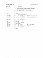
EV80C196KB Microcontroller Evaluation Board User’s Manual 4 3The BUSWIDTH output of the EPLD, pin 16, is fed into the buswidth pin of the
8OC196KB. Therefore, it is driven low for accesses to 8-bit memory and high for
accesses to 16-bit memory. As shipped, it goes low simultaneously with CE2 or
CS510 as these are the only areas of memory mapped as 8-bit.
Programmed into the EPLD is a 3-bit wait-state machine clocked by the rising edge
of CLKOUT from the 8OC196KB. The transition sequence of the wait-state machine
is controlled by the current state of the machine and the inputs to the EPLD (for
further details see appendix E). While the bus of the 80C196KB is idle the wait-state
machine is locked in state 0, which is called async-start. The conditions for leaving
async-start are 1) ALE being asserted, 2) HLDA# not being asserted and 3) a
value on A8 - Al5 requiring wait-states. Because the falling edge of ALE can occur
before the next rising edge of CLKOUT can clock the wait-state machine, a signal
called STALE (for Stretched ALE) is used. STALE does not go low until after the
rising edge of CLKOUT.
During async-start, the output WAIT# from the EPLD is asserted asynchronously
based upon a value on A8-A15 requiring wait-states. If no wait-states are required,
WAIT# will not be asserted and the wait-state machine will remain in async-start.
However, if one or more wait-states are needed WAIT# will be asserted and the
wait-state machine will transition out of async-start on the next rising edge of
CLKOUT. The next state entered depends on how many wait-states are needed. If
only one is required the next state is remove&old, where WAIT# is deasserted
regardless of the inputs to the EPLD. If two watt-states are needed the next state is
hold-2, where WAIT# is always asserted, then the state after that is remove-hold.
The additional states, hold-3 - hold 7, work just like hold-2 with WAIT# always
asserted. The wait-state machine wJI count through from hold-2 to hold-n to
generate n wait-states before jumping to remove-hold to deassert WAIT#. The
maximum number of wait-states is seven.
The previous paragraph described how the signal WAIT# is generated based on the
rising edge of CLKOUT. However, the 8OC196KB needs to have a valid signal on
it’s READY input pin until the falling edge of CLKOUT. Therefore, it was necessary
to clock WAIT# through a negative-edge-triggered-JK flip-flop (U15A) by the falling
edge of CLKOUT to generate a signal called WAITN#. As in the EPLD, WAITN# is
asserted asynchronously while ALE is high and WAIT# is asserted. After ALE goes
low WAITN# will remain asserted until WAIT# is deassetted and the flip-flop is
clocked. Besides the WAIT# signal, the WAITN# signal can be asserted by the
USEREADY signal from the expansion bus. As shipped, the EPLD has the following
configuration:
Memory
Type
Wait
States
Enable
Signal
Memory Region
in User Mode
ROMsim/RAM
0
CEl
2000H-5FFFH
ROMsim/RAM
0
CE2
6000H-7FFFH
Monitor EPROM
1
CEO
0-FFH, 1DOOH- DFFH
82510 UART
2
cs510
1EOOH-1EFFH
Unimplemented
0
N/A
1OOH-1CFFH, COOOH-FFFFH
Unimplemented
1
N/A
8000H - BFFFH
-14
-
EV8OC196KB Microcontroller Evaluation Board User’s Manual
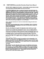
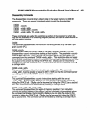
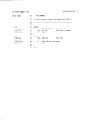
E3 2000H-3FFFH Memory Location
A-B
External
Internal
B-C
E4 Analog Voltage Reference Source
A-B
AVref = VCC
B-i:
AVref = U3/U4
__Avref from JPl
E2 Analog Ground Reference
A-B
AVss = Vss
--Avss from JPl
E7 82510 UART Interrupt Signal to 8OC196KB
A-B
UART Interrupt = EXTINnP2.2
UART lnterrutp = NMI
B-C
L E20 Enable RESET signal from host
A-B
RESET from P2
RESET from Pl
B-C
-mm
Reset circuit insolated
El6 LED Driver Enable
Enabled
A-B
__~
Disabled
-
1
E6 80C196KB CDE U5 pin 14
A-B
CDE = Vss
CDE = Vcc
B-C
i
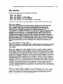
Figure 3a.
Configuration Jumper Locations
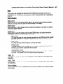
El1 HLDA# Input to PLD U12
A-B
HOLD/HLDA feature in use
--HOLD/HLDA not used
El9 8OC196KB RXD signal from P2
RXD driven by U19 pin 3
A-B
--RXD can be used by JP2
EV80C196KB Microcontroller Evaluation Board User’s Manual
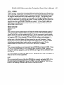
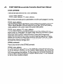
E8 U8 pin 27
Pin 27 = Al 5
A-B
Pin 27 = WRL#
B-C
E9 UlN8 pin 1
Pin 1 = A15
A-B
Pin 1 = Vcc
B-C
El0 Ul/U8 pin 26
Pin 26 = Al 4
A-B
R-C
Pin 26 = Vcc
El2 U13 pin 27
Pin27=A15
A-B
Pin 27 = WRL#k
B-C
El3 U6/U13 pin 1
Pin 1 =A15
A-B
Pin 1 = Vcc
B-C
El4 U6/U13 pin 26
Pin26=A14
A-B
Pin 26 = Vcc
B-C
Pin27=A15
Pin 27 = WRH#
Pin27=A15
Pin 27 = WRH#
t
L
El7 U14 pin 26
A-B
Pin26=A13
Pin 26 = Vcc
B-C
El8 U14 pin 27
Pin27=A14
A-B
Pin 27 = WR#
B-C
El5 U14 pin 1
Pin 1 =A14
A-B
Pin 1 = Vcc
B-C
Pin 1 =A15
Figure 3b.
Memory Configuration Jumper LocationiD
-15
-16-
EV80C196KB Microcontroller Evaluation Board User’s Manual
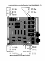
DPl LED Array
/
r
JP2 input/Output Expansion Connector
Ir
L
/
1
2
3
4
5
6
7
6
9
10
P1.0
PI.1
P1.2
P1.3
P1.4
P1.5
P1.6
P1.7
P2.5/PWM#
HSO.O#
JPl Analog Input Connector
/
JP4 Power Connector
JP3 Memory-i/O Expansion Connector
Pl 82510 External UART PortP2 8OC196KB Internal UART Port -
Figure 4.
Expansion Ports, Connectors and LEDs
EV80C196KB Microcontroller Evaluation Board User’s Manual
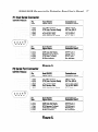
Pl Host Serial Connector
DB-9S RS232
’
Pin
Nos.
Host RS-232
Signal Name
Connection on
Evaluation Board
5 (AB)
4 (CD)
3 @A)
2 WV
1 W=)
SG Signal Ground
DTR Data Terminal Ready
TxD Transmit Data
RxD Receive Data
DCD Data Carrier Detect
Digital Ground
INIT thru E20-C
RxD of 82510
TxD of 82510
DTR Pl-pin 4
Pin
Nos.
Host M-232
Signal Name
Connection on
Evaluation Board
DSR Data Set Ready
RTS Request To Send
CTS Clear To Send
RI Ring Indicator
DTR Pl -pin 4
CTS Pl -pin 8
RTS Pl-pin 7
Run Indicator
6
(CC)
7 (CA)
8
W
9W
Figure 5.
P2 Serial Port Connector
DB-9S RS232
Pin
Nos.
Host W-232
Signal Name
Connection on
Evaluation Board
5 VW
4 (CD)
3 VW
2 W
1 (CF)
SG Signal Ground
DTR Data Terminal Ready
TxD Transmit Data
RxD Receive Data
DCD Data Carrier Detect
Digital Ground
INIT thru E20-A
RxD of 8OC196KB
TxD of 8OC196KB
DTR P2-pin 4
Host M-232
Signal Mame
Connection on
Evaluation Board
DSR Data Set Ready
RTS Request To Send
CTS Clear To Send
RI Ring Indicator
DTR P2-pin 4
CTS PBpin 8
RTS PP-pin 7
No connection
L
rPin
Nos.
6
(CC)
7 GA)
8
W
9W
L
Figure 6.
-17-
-189
EV80C196KB Microcontroller Evaluation Board User’s Manual
JPI Analog Input Connector
2x13 Pin MOLEX 39-51-2604 or Equiv.
ANGND - 1
VREF ---- 3
ANGND - 5
ANGND - 7
VREF ---- 9
ANGND -11
ANGND -13
VREF --- 15
ANGND -17
ANGND -19
VREF --- 21
ANGND -23
VREF --- 25
2 - Analog Channel 0
4 -VREF
6 - Analog Channel 1
8 - Analog Channel 2
10 - VREF
12 - Analog Channel 3
14 - Analog Channel 4
16-VREF
18 - Analog Channel 5
20 - Analog Channel 6
22 - VREF
24 - Analog Channel 7
26 - ANGND
Figure 7.
JP2 I/O Expansion Connector
2x25 Pin MOLEX 39-51-5004 or Equiv.
1 thru 49 - VSS
2 - Pl .O Bi-directional
4 - Pl .l Bi-directional
6 - P1.2 Bi-directional
8 - P1.3 Bi-directional
10 - P1.4 Bi-directional
12 - Pl .YBREQ## Bi-directional
14 - Pl .G/HLDA# Bi-directional
16 - P1.7/HOLD# Bi-directional
18 - P2.0/Txd Output
20 - P2.1/Rxd Bi-directional
22 - P22/Extint Input
24 - P2.3fl2CLK Input
26 - P2.4fl2RST Input
28 - P2.5/PWM Output
30 - P2.6!T2UPDN Bi-directional
32 - P2.7/T2Capture Bi-directional
34 - HSO.0 Output
36 - HSO.l Output
38 - HS0.2 Output
40 - HS0.3 Output
42 - HSI.0 Input
44 - HSI.l Input
46 - HSl.2/HS0.4 Bi-directional
48 - HSl.3/HS0.5 Bi-directional
50 - vcc
Figure 8.
EV80C196KB Microcontroller Evaluation Board User’s Manual
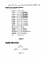
JP3 Memory-l/O Expansion Connector
2x30 Pin MOLEX 39-51-6004 or Equiv.
vcc
__---------------
- 1
r
I7cl
A0 Output ---------- 3 I70
Al Output ---------- 5 I70
A2 Output----------7 I7u
A3 Output ---------- 9 I70
A4 Output --------- 11 I30
A5 Output --------- 13 I3u
A6 output --------- 15 Iq u
A7 Output--------- 17 Iq u
19 Iq u
vss _________-__-----A8 output --------- 21 Iq u
A9 Output --------- 23 Iq u
Al 0 Output ------- 25 Iq u
Al 1 Output ------- 27 Iq u
Al 2 Output ------- 29 q u
Al 3 Output ------- 31 q u
Al 4 Output ------- 33 q u
Al 5 Output ------- 35 q u
vss _______---------- 37 q u
CLKOUT Output - 39 q n
RD# Output ------- 41 q u
BREQ# Output --- 43 q u
ALE Output ------- 45 q u
NMI Input ---------- 47 q u
RESET# Output - 49 q u
No Connection --- 51 q u
HLD4# Output --- 53 q u
-12VDC ________-_-- 55 q u
vss _____-_--------- -- 57 q u
vcc ___------------ --- 59 I q u
2 - vcc
4 - DO Bi-directional
6 - Dl Bi-directional
8 - D2 Bi-directional
10,- D3 Bi-directional
12 - D4 Bi--directional
14 - D5 Bi-directional
16 - D6 Bi-directional
18 - D7 Bi-directional
20 - vss
22 - D8 Bi-directional
24 - D9 Bi-directional
26 - DlO Bi-directioal
28 - Dl 1 Bi-directional
30 - D12 Bi-directional
32 - D13 Bi-directional
34 - D14 Bi-directional
36 - D15 Bi-directional
38 - Vss
40 - vss
42 - WR# Output
44 - BHE# Output
46 - UserReady Input
48 - INST Output
50 - P2.2/EXINT Bi-directional
52 - No Connection
54 - HOLD# Input
56 - +12VDC
58 - Vss
60 - Vcc
Figure 9.
JP4 Power Supply Connector
4 Pin MOLEX 26-03-3041 or Equiv.
Figure 10.
-19-
-2o-
EV80C196KB Microcontroller Evaluation Board User’s Manual
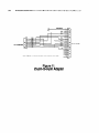
To host PC
To Evalboard
Note: Signal mneumonics are reference to the host.
Figure 11.
25pin-to-g-pin Adapter
EV8OCI 96KB Microcontroller Evaluation Board User’s Manual
INTRODUCTION TO iRISM-IECM SOFTWARE
The EV80C196KB board uses an Embedded Controller Monitor (ECM) written for
the MCS-96 family of 16-bit microcontrollers. This monitor supports basic debug
facilities (LOAD, GO, STEP etc.) in the user’s target system. The ECM is broken
into two independent programs, one of these executes in the EV80C196KB (iRISM96KB) and the other executes in a IBM PC or BIOS compatible clone(iECM-96).
These two programs communicate via an asynchronous serial channel using a
binary protocol defined specifically for this application.
The partitioning of the ECM into two separate programs supports a number of goals
in the development of this system:
The system is easy to adapt to a new target because the code which runs in
the target is very simple and small.
The feature set of the user interface is not limited by the resources of the
target since the user interface is implemented in the host PC.
Concurrent operation of the ECM and the target system was easily achieved.
This allows you to interrogate and (carefully) modify the state of the target
system while it is running.
This manual section describes the user interface provided by the iECM-96, the
interface between this PC resident software and the target resident software, and
the structure of the software in the target. Appendix B lists the resources of the
80C196KB that are reserved for this RISM implementation. Appendix C is the listing
for the iRlSM software which runs in the 80C196KB on this board. It uses an Intel
82510 UART for host communications.
The iECM-96 was designed and implemented by Intel to support user’s of the MCS96 architecture, and is placed in the public domain with no restrictions or warranties
of any kind.
Features
Host system is an IBM PC AT, PC XT, or BIOS-compatible
via COMl or COM2 at 9600 baud.)
clone. (Interfaces
Sixteen software execution breakpoints
Concurrent interrogation of target memory and registers
Supports BYTE, CHARACTER,
FPAL-96 REAL variable types.
WORD, STRING, DOUBLE-WORD
Single-Line Assembler/Disassembler
Symbolics compatible with Intel’s OMF debug records
Supports LOAD, SAVE, LIST, LOG, and command INCLUDE files.
and
-211
EV80C196KB Microcontroller Evaluation Board User’s Manual
Restrictions
Two words of user stack are reserved for use by the iRISM-96 software.Other
memory and/or registers in the target memory will be used by the iRISM-96
software. The exact number and location of this memory is implementation
dependent. See appendix B or C for further information.
An asynchronous serial port capable of operation at 9600 baud must be
available in the target system. The RISM described in this document uses an
Intel 82510 UART. This version also uses the NMI (Non-Maskable Interrupt)
to signal that a received data character is available.
1 The TRAP instruction is reserved.
Breakpoints and program stepping will not operate if the user’s code is in
EPROM or other nonchangeable memory.
EV8OC196KB Microcontroller Evaluation Board User’s Manual
OVERVIEW
Embedded Controller Monitor (ECM)
An ECM (Embedded Controller Monitor) provides basic debug capability and is
installed in your target system. Capabilities include loading object files into system
RAM, examining and modifying variables, executing code, and stepping through
code. In the past, most of these monitors have been configured to run with a standard “dumb” CRT with some form of auxiliary port for loading and saving object code
from a host system. It is now common for a personal computer to act as the host for
program translation and also emulate a dumb CRT during user interaction with the
ECM. The ECM developed for the MCS-96 family makes the assumption that the
user interface will always be a personal computer; no provision is made for interface
to a dumb CRT. By making this assumption it is possible to reduce the size and
complexity of the code that must be installed in the target system. A term’ has been
coined for this code resident in the target -- RISM. The term RISM stands for Reduced instruction Set Monitor and is an obvious takeoff of the term RISC (Reduced
Instruction Set Computer) used to describe a class of computer architectures. The
RISM consists of about 300 bytes of MCS-96 code which provide primitive operations. Software running in the host uses the RISM commands to provide a complete
user interface to the target system. The advantage of this approach is that the ECM
can be readily adapted to different target systems and requires only a small part of
the available target memory space. The disadvantage is that the user interface
must be provided by a personal computer.
The structure of the RISM is a short section of initialization code and an interrupt
service routine (ISR) that processes interrupts from the host system. The RISM ISR
consists of a short prologue and then a case-jump to one of 20 to 25 command
executors. These executors are simple and short; the flow though the entire ISR
(including the prologue) is 15-20 instructions. The serial communication occurs at
9600 baud, which limits the frequency of these interrupts to 1 Khz. In the worst case
the EV80C196KB board will be slowed by the execution of a fairly short RISM ISR
every millisecond while executing user code. It is possible to operate the
EV80C196KB board so that no real-time is lost to the iECM-96 unless the user is
actively interrogating the target. (See the section “Initiating and Terminating the
iECM-96” and the description of the RISM REPORT-STATUS command for details
on this).
-239
-240
EV80C196KB Microcontroller Evaluation Board User’s Manual
USER INTERFACE
The user interface to the iECM-96 supports commands to initiate and configure the
ECM-96, perform I/O operations involving DOS files, execute user programs, and
interrogate variables in the target system. Interrogation can be done in a number of
formats and in most cases can be done concurrently with user code execution. A
single line assembler and disassembler are also provided.
Note: on the disk included with the Ev80C196KB is a file called DEMO.LOG.
DEMO.LOG is a sample iECM-96 session for you to invoke and become more
-familiar with the features of iECM-96. Appendix G is a printout of DEMO.LST
which was created by turning on the list feature and invoking DEMO.LOG by
typing *‘include demo.log”<CR> at the iECM-96 “*‘* prompt.
Background Information
Numeric and Symbolic Input
The command parser used by the iECM-96 software requires that numeric inputs
always start with the digits O-9. If hexadecimal numbers are entered which start with
A-F they must be preceded by a “0”. For example, enter “OAA55” instead of “AA55”.
This requirement is similar to ASM-96. If symbolic information has been downloaded
as part of an object file (see “Loading and Saving Object Code”) then you can enter
a valid symbol name whenever a number is expected. The symbol name must be
preceded by a period (“.“) so that the parser knows to try searching the symbol
table. If the symbol is ambiguous then it will not be accepted by the parser. The
probability of ambiguous references can be reduced by specifying the module name
along with the symbol name. The module name must be preceded with a colon (“:“).
If a variable TEMP is declared both in MODULE1 and in MODULE2, then a reference to the TEMP declared by MODULE1 would be “:MODULEl .TEMP”. PLM-96
or C-96 line numbers can be called out by a pound sign (“#“) followed by the line
number.
Symbolic Output
The symbolic output routines, in general, deal only with address information. They
will not try to convert data values into symbolic form. When the symbol table is
searched for a symbol name to associate with a given value the routines also perform type checking. If one, and only one, symbol matches both the type and value
of the address being displayed then the output routines will display the symbol name
along with the numeric value of the address. If more than one label has been assigned to a given address then the symbolic output routines will ignore all of them.
The exception to this rule occurs when the disassembler finds multiple labels assigned to a given code address. The disassembler will display all the known symbolic labels attached to a code address.
If the symbols table gets very large the symbolic output routines will become painfully slow, particularly on an 8088 based PC. This problem can be avoided by using
modular programming and translating a subset of the modules in the debug mode.
Another alternative is to use the “SYMBOLS OFF” command to suppress symbolic
output Symbolic input is not affected by this command.
EV80C196KB Microcontroller Evaluation Board User’s Manual
Controlling Lengthy Commands
Most of the commands supported by iECM-96 appear to complete without delay.
Some commands (e.g. displaying or filling a large area of memory) take an appreciable length of time to complete. In general these commands can be aborted by
entering a CARRIAGE-RETURN.
Those commands which display a large amount
of information can be paused by hitting the SPACE bar. After you have checked the
data currently on the screen you can depress the SPACE bar again to resume the
output.
Aborting from iECM-96
Entering a control-C will cause the iECM-96 to close any open files and return to
DOS.
Initiating and Terminating iECM=96
This section describes the commands for invoking iECM-96 from DOS and exiting
back to DOS.
ECM96
This command, entered at the DOS prompt, loads the iECM-96 software and executes it. Several options are available with this command. Option strings always
start with a hyphen (“-‘I) and can be entered in upper or lower case. The operation
of these options is described below. Any or all of these options can be entered in
any order, if the options are contradictory then the actual option accepted is the last
one entered.
-COM2, -COMl
These options tell the iECM-96 software which serial communication port is to be
used. If neither of these options is entered then COMl will be used as a default. If
iECM-96 detects valid CTS (Clear To Send) and DSR (Data Set Ready) signals from
the appropriate COM port it will sign on and display a command prompt. If the target
is stopped the command prompt will be an asterisk (“*“). If the target is already
running the prompt will be a greater-than sign (5”).
-DIAG
If CTS or DSR are not present, iECM-96 will complain about it and ask if you want to
proceed or exit. It is possible, but not likely, that iECM-96 will operate properly even
after compl’aining. It is more likely that there is a problem with the serial port or the
cabling which will prevent proper operation. If the problem is not obvious (e.g.
disconnected cable or no power to the target hardware) then the -DIAG invocation
option can be used to help isolate the problem. The -DIAG option puts the iECM-96
system in a special mode which allows many tests to be used to find interfacing
problems, or target bugs.
The diagnostic mode is intended to support debugging of boards which use the
iECM-96. It can be particularly useful in systems which have multiple address
decoding modes, such as the EV80C196KB. Upon reset this board has EPROM at
location 2080H, the address where the 8OC196KB starts execution. After executing
some initialization code, the board can change the address decoding so that
ROMsim/RAM is available in the partition which contains 2080H and the RISM is
relocated to another area. This allows you to download code which is designed to
operate in the on-chip ROM of MCS-96 family parts (2000H - 3FFFH). The diagnostic mode allows the use of diagnostic routines which disappear from memory space
-25
-269
EV80C196KB Microcontroller Evaluation Board User’s Manual
when the RAM is mapped into the system. It also provides a simple routine to check
the communications interface between the host and the target.
In the EV80C196KB board, there is a serial port loop-back mode which allows debugging the host/board interface. Upon reset the board is in the echo mode. Until it
receives an ASCII slash (I’/“) or reverse-slash (‘7”) it will increment every character it
receives from the host and send the incremented value back to the host. It will also
display the binary code of the character the board received on the Port 1 LED%. If a
reverse slash is received by the RISM it will leave the echo mode (set USER MAP
flag true), remap memory and start normal operation. If a slash is received it-will
stop echoing incremented received data and start responding to RISM commands
with the diagnostic flag set. In this mode there are diagnostic routines resident in
EPROM which are useful for debugging the board. Initially after invoking the diagnostic mode, the Program Counter points to the beginning of a RAM test at 2200H.
See the source code listing in appendix C for further details.
Note: The target hardware will have to be reset before using the DIAG command option.
Note: When executing diagnostic routines from EPROM, certain commands
such as Breakpoints and Stepping will not work as they need to modify the
code to work properly.
When the host software is invoked in the diagnostic mode it will tell you to enter
characters on the keyboard. These characters will be sent to the target and the
response from the target will be displayed on screen. This is a simple confidence
check on the serial communication channel. You are told to enter a slash or reverse-slash to terminate this mode and proceed in either the diagnostic mode or the
normal user’s mode. If the user interface is invoked without the -DIAG option it will
immediately transmit a reverse-slash which should put the target in the normal
mode. Systems which do not implement the diagnostic mode will load the reverseslash into the RISM-DATA register where it will languish till more useful data is sent
by the host.
-8096, -8096BH, -Cl 96KB
These three options control the single line assembler and the disassembler in the
iECM-96. If the 8096 (8x9x-90) or 8096BH (8x9xBH) options are selected then the
additional instructions in the 8OC196KB will be considered invalid for both the single
line assembler and the disassembler. If none of these options are selected then the
iECM-96 will default to Cl 96KB mode.
-NOTYPES
This option will cause the object file loader to ignore type definition records in the
object module. If this is invoked then the symbolic I/O routines will only recognize
basic data types such as BYTES, WORDS, and LONGS. More complex data types
such as PLM arrays and structures will not be recognized. This option is included
because early versions of the host software got confused while loading certain type
definition records generated by C-96. These problems have been fixed but the
option was left in case similar problems remain.
EV80C196KB Microcontroller Evaluation Board User’s Manual
-POLL, -SIGNAL
These two options control how the host software detects whether or not the user’s
code is running. If poll mode is selected then the host will periodically poll the target
with a REPORT-STATUS command. This takes no additional hardware but forces
the target to waste instruction cycles responding to the poll. The signaling mode
avoids this overhead but requires that the target set the Ring Indicator modem
control line whenever it is running user code. The user interface will then check this
line before it issues a REPORT STATUS command. If neither of these options is
selected then the signal mode isselected as a default. On the EV80C196KB the
OUT1 # pin of the 82510 is used to generate this running signal. Therefore, the
signal mode is recommend.
RESET SYSTEM
RES SYSTEM
RESET
RES
This command and its abbreviations will reset the entire target hardware system if
the target system is implemented to support this operation. On the EV80C196KB
jumper shunt E20 must be installed from B to C for this command to work properly.
This command operates by dropping the DTR modem control line. This comes into
the target as DSR. After dropping DTR the iECM-96 software will wait about 1
second to allow the target to complete its initialization routines. The iECM-96 will
politely warn of this time delay and then ignore the user until it expires. Unless
special precautions are taken in the design of the target system, any data in RAM
(including downloaded object code) may be corrupted by the reset. On the
EV80C196KB, the RAM contents should not be affected by a RESET.
DOS
This command enables you to temporarily leave iECM-96 and return to DOS. Once
you have suspended iECM, you may perform other functions in DOS, including
using other software programs, such as ASM-96, as long as there is sufficient memory to do so.
To reenter iECM, type exit at the DOS prompt.
effect at the time it was suspended.
iECM will return with all conditions in
QUIT
This command will close any files that iECM-96 has opened and exit to DOS. Note
that this command can be used even if the target is running. iECM-96 sets the
selected COM port to 9600 baud, 8 bits, no parity, and one STOP bit. The port will
be left in this state by iECM-96 when control is returned to DOS.
-27-
-289
EV80C196KB Microcontroller Evaluation Board User’s Manual
Default Base Commands
These commands are used to set the default base for numeric input and output. The
valid bases are: 16 (hexadecimal) , 10 (decimal), and 8 (octal). The default base is
used to display variables. It is not used to display addresses (which are displayed in
hexadecimal) or breakpoint numbers (which are displayed in decimal). The default
base is also used to enter numbers into the command parser, but it is possible to
override the default base during input by adding a character at the end of the number which forces the appropriate base to be used. The override characters are H (or
h) for hexadecimal, T (or t) for decimal, and 0 (or o) for octal. The override character must appear immediately following the last digit of the number with no intervening space.
BASE
This command will display the current default base.
BASE=cvalid-base>
This command will set the current default base to <valid-base>. When entering this
command it is advisable to use an override character to select the new default base:
BASE=1 00
BASE=1 OT
BASE=1 OH
; selects octal
; selects decimal
; selects hexadecimal
This avoids confusion when changing bases. As an example of the confusion which
is avoided, consider the following commands entered while the base is hexadecimal.
The command:
BASE=1 0
will leave the default base as hexadecimal and the command:
BASE=1 6
will result in an error because 16H (22T) is not a valid base. The command:
BASE=OA
will select decimal as the default base but it is cleaner and simpler to use the override character:
BASE=1 OT
This works independently of the current default base and leaves a useful record in
log or list files which may be open.
EV80C196KB Microcontroller Evaluation Board User’s Manual -29FILE OPERATIONS
iECM-96 uses files in the host system to load and save object code, enter predefined strings of commands, to keep a log of commands that are entered by the user,
and to keep a record of an entire debug session which includes both the characters
entered by the user and the response generated by iECM-96 on the host screen.
The commands which operate with files are described in the following sections.
Loading and Saving Object Code
iECM-96 accepts object files which are generated by Intel’s development tools.
iECM-96 will not accept files which contain unresolved externals or files which contain relocatable records. These files must be passed through RL-96 in order to
resolve the externals and/or absolutely locate the relocatable segments. iECM-96
will also not accept HEX format files. There is a utility on the disk (HEXOBJ.EXE)
for converting HEX format files to Intel object format files loadable by iECM-96.
While still in DOS type “HEXOBJ <filename>.hex <filename>.obj”cCR> to convert
<filename>.hex to a usable format for iECM-96. HEXOBJ does not attempt to convert any symbolic information contained in the HEX file. The iECM-96 commands
which operate on object files are:
LOAD <filename>
LOADSYM <filename>
SAVE caddr> TO <addr> IN <filename>
The metasymbol <filename> means that a valid MS-DOS file name must be entered
in that position of the command string.
LOAD <filename>
This command loads the content records of the object file <filename> into the target
memory and loads any associated symbolic information into a symbol table maintained in the host system’s memory.
LOADSYM <filename>
This command loads the symbolic information from <filename, into the symbol table
maintained in the host system but does not load the content records into the target’s
memory. This command is useful when you have left a debug session with the
target still running a program that has been loaded. At a later time you can reinvoke iECM-96 and interrogate the running program without stopping it. The
LOADSYM command allows the use of the symbolic information contained in the
object file without reloading the content records. (Content records cannot be loaded
while the target is running).
SAVE caddr> TO caddr> IN <filename>
This command saves a region of memory as an object file which can be reloaded
into the target memory at some latter time. No attempt is made to include any
symbolic information which may have been in the symbol table maintained in the
host system.
-301
EV80C196KB Microcontroller Evaluation Board User‘s Manual
Other File Operations
In addition to object files, the iECM-96 makes use of include files, log files, and list
files. Include files contain commands to be executed by iECM-96, they must contain
the exact sequence of ASCII characters that you would enter from the keyboard to
execute the command. Include files can be tedious to generate with a text editor so
iECM-96 can generate log files in which are stored characters entered by the user.
The intent is that log files be used later as include files to recreate command sequences. List files keep a running record of both commands entered by the user
and of the response generated by iECM-96. Comments can be included in list and
log files to make them easier to understand. A comment starts with a semicolon (I;‘)
and ends with a carriage return or ESC. The semicolon is considered to be part of
the comment but not the CR or ESC. The command parser will ignore comments
but will put them in the list and log files.
Note: on the software disk included with the EV80C196KB is a file called
DEMO.LOG. DEMO.LOG is a sample iECM-96 session for you to invoke and
become more familiar with the features of iECM-96. Appendix G is a printout
of DEMO.LST which was created by turning on the list feature and invoking
DEMO.LOG by typing ‘*include demo.log”<CR> at the iECM-96 *‘*” prompt.
The list and log files commands allow for default filenames and allow either overwriting existing data in the file or appending data at the end of the file. This allows you
to gather list and log data in the default files which avoids the creation and management of a large number of separate files. Log and list files are stamped with the
date and time whenever they are opened to make it easier to use this capability and
then go back and sort out the data from several debug sessions with a text editor.
The commands involved in include, log, and list operations are:
INCLUDE <filename>
F’AUSE LIST
LIST <filename>
LOG
~;XY;~~narne>
LISTON
LOGOFF
LOGON
Three of these commands require you to supply a valid file name, the rest use the
appropriate file name that has already been entered.
INCLUDE <filename>
This command will attempt to open <filename> as a read only file. If the file can be
opened then the command parser will take commands from that file until the end of
the file is reached. The include file will then be closed. Only one include file will be
opened at a time.
EV80C196KB Microcontroller Evaluation Board User’s Manual -31PAUSE
This command is documented in this section because it is intended to be used as
part of INCLUDE files. It is not really a file oriented command itself. When this
command is entered the iECM-96 will stop parsing commands until a SPACE character is entered from the keyboard (it can’t come from an INCLUDE file). This provides a method of pausing in the middle of an INCLUDE file operation until you have
a chance to see what’s going on and acknowledge the pause condition by depressing the SPACE bar.
LIST
This command behaves like the LIST <filename> command described below except
that it uses the last <filename> that was entered as part of a LIST <filename> command: If no such command has been entered then the default filename “LIST.ECM”
will be used.
LIST <filename>
This command will attempt to open <filename> as a writable file. If a file with cfilename> already exists then iECM-96 will ask if the file is to be overwritten or if the
new data should be appended to the end of the existing file. It will then open the file
and stamp it with the current date and time from the system clock. After this, commands entered by the user and the responses generated by iECM-96 will be recorded in the file.
LOG
This command behaves like the LOG <filename> command described below except
that it uses the last <filename> that was entered as part of a LOG <filename> command. If no such command has been entered then the default filename “LOG.ECM”
will be used.
LOG <filename>
This command will attempt to open <filename> as a writable file. If a file with cfilename> already exists then iECM-96 will ask if the file is to be overwritten or if the
new data should be appended to the end of the file. It will then open the file and
stamp it with the current date and time. After this, commands entered by the user
will be recorded in the file. Note that this file may contain nonprintable characters
(e.g. ESC).
LISTOFF and LISTON
The LISTOFF closes a LIST file that has been specified by the LIST command. This
stops new list information from being recorded. The LISTON re-opens the list file in
the append mode so that recording can start again. LISTON also stamps the list file
with the current date and time from the system clock.
LOGOFF and LOGON
The LOGOFF closes a log file that has been specified by the LOG command. This
stops new list information from being recorded. The LOGON re-opens the log file in
the append mode so that recording can start again. LOGON also stamps the list file
with the current date and time from the system clock.
EV80C196KB Microcontroller Evaluation Board User’s Manual
PROGRAM CONTROL
Commands which control program execution allow you to reset the processor, set
execution breakpoints, start execution, stop execution, step, and super step. The
commands will be grouped by their major function for the sake of discussion.
Resetting the Target
The processor can be reset by executing the iECM-96 command:
RESET CHIP
This command physically resets the processor by setting the RISM-DATA register
to OXXXXOOOl and issuing a MONITOR-ESC RISM command which will cause the
target to perform a RST instruction.
Breakpoints
iECM-96 provides sixteen program execution breakpoints. If a given breakpoint is
inactive it is set to zero, if it is active then it is set to the address of the first byte of an
instruction. Breakpoints set to addresses which are not the first byte of an instruction
will cause unpredictable errors in the execution of the user’s code. When execution
is started iECM-96 saves the user code byte at any active breakpoint and substitutes a TRAP instruction for that byte. Executing a TRAP instruction will cause the
iECM-96 to restore the user code bytes where the TRAP instructions were substituted and then decrement the user’s program counter so that it points at the original
instruction. The user’s program will appear to stop execution immediately before
executing the instruction with a breakpoint set on it. All the TRAPS will be removed
from the user’s code and the original code restored.
Note: Most monitor programs similar to iECM-96 display a message on the
console when a break occurs (e.g. “Program break at 1234H”). This is not
done in iECM-96 because the system supports concurrent interrogation of the
target which the user’s code is running; it is possible (perhaps probable) that
the break will occur while you are in the middle of displaying or modifying the
state of the target. Any special break message would have to interrupt the
execution of the command. Because of this the iECM-96 does not output a
special break message. You have two ways to find out that a break occurred:
I)- The prompt will change from a greater-than 5” to an asterisk (“*“).
2). The status of the processor shown in the “control panel” at the top of the console
screen will change from “running” to “stopped”.
Commands which set the breakpoint array are:
:l[
cbp-number>
BR [ cbp-number>
The square brackets
and must be entered
used to describe the
ning but they cannot
]
] = <code-addr>
in the latter two commands are part of the command syntax
by the user, the angle brackets are part of the “meta” language
syntax. Breakpoints can be displayed while your code is runbe modified.
EV80C196KB Microcontroller Evaluation Board User’s Manual
NOTE: BR[O] and BR[l] can also be set by the GO command by using the TILL
clause; all of the breakpoints will be cleared by the GO command if the FOREVER clause is used.
BR
This command will display all of the active breakpoints (i.e. those not set to zero).
You will also be informed if no breakpoints are active.
BR [ cbp-number> ]
This command will display the setting of the selected breakpoint and wait for input
from you. If you enter a carriage-return the command will terminate. If you enter an
ESC the next sequential breakpoint will be displayed. If you enter a numeric value
then the selected breakpoint will be loaded with the value and the iECM-96 will
again wait for input. At this point you can enter either a CARRIAGE-RETURN or an
ESC. As before, the ESC will cause the iECM-96 to display the next breakpoint and
the CARRIAGE-RETURN will terminate the command. This command will wrap
around from the last breakpoint (1%) to the first breakpoint (0).
BR [ cbp-number> ] = <code-addr>
This command sets the specific breakpoint specified by cbp-number>
<code-addr>.
to the value
Program Execution
These commands start and stop execution of user code. The commands provided
are:
2: FOREVER
GO FROM <code-addr>
GO FROM <code-addr> FOREVER
GO FROM <code addr> TILL <code-addr>
GO FROM ccodezaddr> TILL <code-addr>
GO TILL <code-addr>
;AqflLL <code-addr> OR <code-addr>
OR <code-addr>
If a GO with breakpoint command is entered, the user code bytes at the breakpoints
will be saved and TRAPS will be installed. When a breakpoint is reached the user’s
software will stop before the instruction which caused the breakpoint and the IECM96 software will restore the original user code. Note that this is different from the
operation of iSBE(and most ICE modules) which stop just afterthe instruction
executes. A problem associated with stopping before the break instruction executes
is that subsequent GO commands may run into the breakpoint before any user code
is executed. The iECM-96 avoids this problem by skipping the setting of any breakpoints set on the instruction that the current PC points to. If this happens to remove
the last breakpoint set then you will be warned but the GO will still execute with no
breakpoints enabled. IF this happens you can use the HALT command to stop the
program a
-33-
-34-
EV80C196KB Microcontroller Evaluation Board User’s Manual
None of the GO commands can be executed while the user’s code is already running; the HALT command cannot be executed if the user’s code is not running. The
GO commands which set breakpoints use BP[O] and possibly BP[l]. Any break
value already in one of these breakpoints will be overwritten and destroyed by these
GO commands. If possible the user should reserve the first two breakpoints for use
by the GO commands and set the remaining breakpoints (if required) explicitly with
the BR commands.
GO
This command starts execution of the user’s code using the current value of user’s
PC and the current breakpoint array.
GO FOREVER
This command clears the breakpoint array and starts execution at the current value
of the user’s PC.
GO FROM <code addr>
This command loads the user’s PC with <code-addr>
user’s code using the current breakpoint array.
and starts execution of the
GO FROM <code-addr> FOREVER
This command loads the user’s PC with <code-addr>,
and starts execution of the user’s code.
clears the breakpoint array,
GO FROM <code addr> TILL <code addr>
This command lo& the user’s PC w%h the <code-addr> which follows the FROM
keyword, sets the first breakpoint (BP[O]) to the <code-addr> which follows the TILL
keyword, and then starts execution of the user’s code.
GO FROM <code-addr> TILL <code-addr> OR <code-addr>
This command acts like the previous command except that it also sets the second
breakpoint (BP[l]) to the ccode_addr> which follows the OR keyword.
GO TILL <code-addr>
This command sets the first breakpoint (BP[O]) to <code-addr> and then starts the
execution of user code using the current setting of the user’s PC and the breakpoint
array 0
GO TILL <code-addr> OR <code addr>
This command acts like the previ&s command except that it also sets the second
breakpoint (BP11J) to the <code-addr> which follows the OR keyword.
HALT
This command stops execution of user code by forcing the processor to execute a
jump to self instruction in a reserved location.
EV80C196KB Microcontroller Evaluation Board User’s Manual -35,
Program Stepping
These commands allow stepping through programs one instruction at a time. Between instructions the iECM-96 commands can be used to check the state of the
variables changed by the instruction to ensure that the program is operating properly. Stepping through code allows a far more detailed look at what is going on in the
program. The price that is paid for this detail is that stepping does not occur in real
time; this makes it difficult or perhaps impossible to use on code that is tied to real
time events.
Stepping
routines
problem
interrupt
while interrupts are enabled would be confusing since interrupt service
will be stepped through as well as sequential code. iECM-96 avoids this
by artificially locking out interrupts while stepping, ignoring the state of the
enable (El) or interrupt mask.
Super-Stepping is similar to stepping except that interrupts are not artificially suppressed. Also, an interrupt service routine or a subroutine call (and the body of the
subroutine that is called) is treated as one indivisible instruction by the super-step
command. This allows the user to ignore the details of subroutines and interrupt
service routines while checking out code. Every time an instruction is “superstepped” all the service routines associated with enabled pending interrupts will be
executed. This may allow limited stepping through code while operating in a concurrent environment but the system will not operate in real time. A better approach is to
use the GO command to execute to a specified breakpoint and then step through
the code being tested looking for proper operation.
iECM-96 implements the step operation by using the TRAP instruction. To step over
a given instruction iECM-96 determines all the possible subsequent instructions and
places TRAPS at these locations. After doing this it allows the user’s program to
execute until it runs into one of these TRAPS and then restores all of the user code
bytes which were overwritten with TRAPS. If iECM-96 is to step over a conditional
branch, two possible subsequent instructions exist in the sequential code of the
program. Any other instruction can only have one “next” instruction. A TRAP is also
set at location 2080H in case the target is reset during the step.
Super-stepping is accomplished by setting TRAPS like the STEP except for CALL
instructions which are treated as a special case. During a STEP the iECM-96 will put
the TRAP at the target address of a call; during a super-step the TRAP will be
placed at the instruction following the CALL. Interrupts are suppressed during STEP
(not SS) operations by saving the user’s El bit, clearing it before the STEP occurs,
and then restoring it. In order to make sure the instruction which is executed does
not modify the El bit, several instructions (PUSHF, POPF, PUSHA, POPA, DI, El)
are simulated by the iECM-96 software rather than being executed by the target
processor. The 80C196KB instruction IDLPD is also simulated during STEP to
prevent the target from locking up. The simulation treats the IDLPD as a two byte
NO-OP. Note that the simulation of instructions only occurs during STEP operations During a GO or SS command all instructions are executed by the target.
-360
EV80C196KB Microcontroller Evaluation Board User’s Manual
The iECM-96 commands which implement step operations are:
STEP
STEP <count>
STEP FROM <code-addr>
STEP FROM <code-addr>
<count>
ss
SS <count>
SS FROM <code-addr>
SS FROM <code-addr>
<count>
Aside from the style of the actual step operation, the SS and STEP commands
beha\ie the same. They will be described together and will be called single-stepping.
{STEP 1SS}
This command single-steps one time.
{STEP 1SS } <count>
This command single-steps <count> times.
{ STEP 1SS } FROM <code-addr>
This command loads the user’s pc (PC) with <code-addr>
one time.
and then single-steps
{ STEP 1SS } FROM <code-addr> <count>
This command loads the user’s pc (PC) with <code-addr>
<count> times.
and then single-steps
EV80C196KB Microcontroller Evaluation Board User’s Manual -37DISPLAYING AND MODIFYING PROGRAM VARIABLES
iECM-96 provides commands to display and modify program variables in several
formats. In addition to simple variables such as bytes and words, more complicated
variables such as reals and character strings are supported. iECM-96 commands
allow variables to be displayed or initialized either individually or as regions of memory which contain variables of the given type.
Supported Data Types
BYTE
A BYTE is an eight-bit variable. No alignment rules are enforced for BYTE variables.
CHAR
A CHAR is a special case of a BYTE. CHAR variables are displayed as ASCII characters.
WORD
A WORD is a 16-bit variable. The address of a WORD is the address of its least
significant byte. A WORD must start at an even byte address.
DWORD
A DWORD is a 32-bit variable. The address of a DWORD is the address of its least
significant byte. A DWORD must always start at an even byte address. If a DWORD
variable is to be accessed as a register by an 8096 instruction then a more restrictive alignment rule is enforced: it must start at an address which is evenly divisible
by 4. This more restrictive alignment rule will only apply to iECM-96 commands
when using the single line assembler.
REAL
A REAL is a 32-bit binary floating point number which conforms to the FPAL96
definition. The 32 bits contain a sign bit, an 8-bit exponent field, and a 23-bit fraction
field. iECM-96 commands use standard scientific notation to deal with REAL numbers Note that the FPAL96 has special representations for +infinity and for NaN’s
(Not a Number--used to signal error conditions) if iECM-96 detects one of these
special values it will output an appropriate text string instead of trying to display the
value in scientific notation.
STACK
A STACK variable is a 16-bit variable which resides in the system stack. The addresses of stack variables (cstack7addr> are taken to be relative to the current
stack pointer and must be word alrgned.
STRING
A STRING is a sequence of ASCII characters which are terminated by the NUL
character. The ASCII character NUL has the binary value of zero.
In addition to supporting access to variables of the above types, iECM-96 also
provides commands to access the special program variables PC (program counter),
PSW (program status word) and SP (stack pointer). These commands are discussed at the end of this section under the heading “Processor Variables”.
-389
EV80Cl96KB Microcontroller Evaluation Board User’s Manual
BYTE Commands
There are four forms for the BYTE commands:
BYTE
BYTE
BYTE
BYTE
<byte-address>
<byte-address>
<byte-address>
<byte-address>
= <byte-value>
TO <byte-address>
TO <byte-address>
= <byte-value>
All of these commands can be used whether or not the user’s program is running.
BYTE <byte-address>
This form is used to examine and then possibly change one or more sequential
BYTE variables. When this command is invoked iECM-96 will display the
<byte-address> symbolically if a valid symbol exists for that <byte-address>.
Whether or not the symbolic display occurs, iECM-96 will display the
<byte-address> in hexadecimal notation, the value of the BYTE in the default base
and wait for an input from you. You can respond with a CARRIAGE-RETURN
character, an ESC character, or by entering a numeric value. A CARRIAGE-RETURN will terminate the command. An ESC will result in the display of the next
sequential BYTE variable. If a numeric value is entered then the BYTE variable will
be set to this value and the iECM-96 will again wait for input. At this point you can
respond only with an ESC or CARRIAGE-RETURN.
As before, the ESC will display
the next sequential BYTE and the CARRIAGE-RETURN will terminate the command.
BYTE <byte-address> = <byte value>
This form is used to set an indizdual BYTE variable without first checking its current
value. When invoked, this command sets the BYTE variable at <byte-address> to
<byte-value>.
BYTE <byte-address> TO cbyte_address>
This form is used to display a region of memory as a sequence of BYTE variables.
When this command is invoked, iECM-96 will start by displaying the current default
base and then a series of lines showing the contents of the selected memory region.
16a symbol exists in iECM-96’s symbol table for the next <byte-address> then this
symbol will be displayed. Whether or not the symbolic display happens, the next line
will start with a hexadecimal display of the address of the next BYTE variable to be
displayed followed by the display of up to 16 bytes of memory as BYTE variables in
the default base. A new line will be started whenever 16 bytes of memory have been
displayed on the line or a valid symbol exists in iECM-96’s symbol table for the next
<byte-address> to be displayed. The command terminates when all of the BYTE
variables in the selected range have been displayed. During lengthy displays you
can stop the output to the console by hitting the SPACE bar. Display can be resumed by hitting the SPACE bar a second time. The command can be terminated by
entering a carriage return.
BYTE <byte-address> TO <byte-address> = <byte-value>This form is used to
initialize a region of memory to the given <byte-value>. Note that this command will
take a little over a millisecond (at 9600 baud) for each BYTE loaded. This command
can be terminated by entering a carriage return but this leaves only part of the
memory region initialized.
EV80Cl96KB Microcontroller Evaluation Board User’s Manual
WORD Commands
There are four basic forms for the WORD commands:
WORD
WORD
WORD
WORD
<word address>
<word-address> = <word value>
<word-address> TO <word address>
<wordaddress>
TO cwordIaddress> = <word-value>
All of these commands can be used whether or not the user’s program is running.
WORD <word-address>
This form is used to examine and then possibly change one or more sequential
WORD variables. When this command is invoked iECM-96 will display the
<word-address> symbolically if a valid symbol exists for that <word-address>.
Whether or not the symbolic display occurs, iECM-96 will display the
<word-address> in hexadecimal notation, the value of the WORD in the default
base and wait for an input from you. You can respond with a CARRIAGE-RETURN
character, an ESC character, or by entering a numeric value. A CARRIAGE-RETURN will terminate the command. An ESC will result in the display of the next
sequential WORD variable. If a numeric value is entered then the WORD variable
will be set to this value and the iECM-96 will again wait for input. At this point you
can respond only with an ESC or CARRIAGE-RETURN. As before, the ESC will
display the next sequential WORD and the CARRIAGE-RETURN will terminate the
command.
WORD <word-address> = <word-value>
This form is used to set an individual WORD variable without first checking its current value. When invoked, this command sets the WORD variable at
<word-address> to <word-value>.
WORD <word-address> TO <word-address
>This form is used to display a region of memory as a sequence of WORD variables. When this command is invoked, iECM-96 will start by displaying the current
default base and then a series of lines showing the contents of the selected memory
region. If a symbol exists in iECM-96’s symbol table for the next <word-address>
then this symbol will be displayed. Whether or not the symbolic display happens, the
next line wild start with a hexadecimal display of the address of the next WORD
variable to be displayed followed by the display of up to 16 bytes of memory as
WORD variables in the default base. A new line will be started whenever 16 bytes of
memory have been displayed on the line or a valid symbol exists in iECM-96’s
symbol table for the next cword7address> to be displayed. The command terminates when all of the WORD vanables in the selected range have been displayed.
During lengthy displays you can stop the output to the console by hitting the SPACE
bar, Display can be resumed by hitting the SPACE bar a second time. The command can be terminated by entering a carriage return.
WORD <word-address> TO <word address> = <word-value>
This form is used to initialize a region of memory to the given <word-value>. Note
that this command will take a little over a millisecond (at 9600 baud) for each WORD
loaded. This command can be terminated by entering a carriage return but this
leaves only part of the memory region initialized.
-390
-409
EV80Cl96KB Microcontroller Evaluation Board User’s Manual
DWORD Commands
There are four basic forms for the DWORD commands:
DWORD
DWORD
DWORD
DWORD
cdword-address>
cdword address> = cdword-value>
cdwordraddress> TO cdword-address>
cdword-address> TO <dword_address>
= cdword-value>
All of these commands can be used whether or not the user’s program is running.
DWORD cdword-address>
Thisform is used to examine and then possibly change one or more sequential
DWORD variables. When this command is invoked iECM-96 will display the
cdword-address> symbolically if a valid symbol exists for that cdword-address>.
Whether or not the symbolic display occurs, iECM-96 will display the
cdword-address> in hexadecimal notation, the value of the DWORD in the default
base and wait for an input from you. You can respond with a CARRIAGE-RETURN
character, an ESC character, or by enterin a numeric value. A CARRIAGE-RETURN will terminate the command. An ES 8 will result in the display of the next
sequential DWORD variable. If a numeric value is entered then the DWORD variable will be set to this value and the iECM-96 will again wait for input. At this point
you can respond only with an ESC or CARRIAGE-RETURN. As before, the ESC will
z@;i;hde
next sequential DWORD and the CARRIAGE-RETURN WIII terminate the
DWORD cdword-address> = cdword-value>
This form is used to set an individual DWORD variable without first checking its
current value. When invoked, this command sets the DWORD variable at
cdword-address> to cdword-value>.
DWORD cdword-address> TO cdword-address>
This form is used to display a region of memory as a sequence of DWORD variables. When this command is invoked, iECM-96 will start by displaying the current
default base and then a series of lines showing the contents of the selected memory
region. If a symbol exists in iECM-96’s symbol table for the next cdword-address>
then this symbol will be displayed. Whether or not the symbolic display happens, the
next line will start with a hexadecimal display of the address of the next DWORD
variable to be displayed followed by the display of up to 16 bytes of memory as
DWORD variables in the default base. A new line will be started whenever 16 bytes
of memory have been displayed on the line or a valid symbol exists in iECM-96’s
symbol table for the next cdword-address> to be displayed. The command terminates when all of the DWORD vanables in the selected range have been displayed.
During lengthy displays you can stop the output to the console by hitting the SPACE
bar. Display can be resumed by hitting the SPACE bar a second time. The command can be terminated by entering a carriage return.
DWORD cdword-address> TO cdword-address> = cdword-value>
This form is used to initialize a region of memory to the given cdword-value>. Note
that this command will take a little over a millisecond (at 9600 baud) for each
DWORD loaded. This command can be terminated by entering a carriage return but
this leaves only part of the memory region initialized.
EV80C196KB Microcontroller Evaluation Board User’s Manual
REAL Commands
There are four basic forms for the REAL commands:
REAL <real address>
REAL <real-address> = <real value>
REAL <real-address> TO ere&address>
REAL crealIaddress> TO <real-address> = <real-value>
All of these commands can be used whether or not the user’s program is running.
REAL <real-address>
This .form is used to examine and then possibly change one or more sequential
REAL variables. When this command is invoked iECM-96 will display the
<real-address> symbolically if a valid symbol exists for that <real-address>.
Whether or not the symbolic display occurs, iECM-96 will display the
<real address> in hexadecimal notation, the value of the REAL in the default base
and wait for an input from you. You can respond with a CARRIAGE-RETURN
character, an ESC character, or by enterin a numeric value. A CARRIAGE-RETURN will terminate the command. An ES8 will result in the display of the next
sequential REAL variable. If a numeric value is entered then the REAL variable will
be set to this value and the iECM-96 will again wait for input. At this point you can
respond only with an ESC or CARRIAGE-RETURN. As before, the ESC will display
thhnTxt sequentral REAL and the CARRIAGE-RETURN WIIItermrnate the comREAL <real address> = <real value>
This form is-used to set an indkidual REAL variable without first checking its current
value. When invoked, this command sets the REAL variable at <real-address> to
<real-value>.
REAL <real-address> TO <real-address>This form is used to display a region of
memory as a sequence of REAL variables. When this command is invoked, iECM96 will display a series of lines showing the contents of the selected memory region.
If a symbol exists in iECM-96’s symbol table for the next <real-address> then this
symbol will be displayed. Whether or not the symbolic display happens, the next line
will start with a hexadecimal display of the address of the next REAL variable to be
displayed followed by the display of up to 16 bytes of memory as REAL variables in
the default base. A new line will be started whenever 16 bytes of memory have been
displayed on the line or a valid symbol exists in iECM-96’s symbol table for the next
<real-address> to be displayed. The command terminates when all of the REAL
variables in the selected range have been displayed. During lengthy displays you
can stop the output to the console by hitting the SPACE bar. Display can be resumed by hitting the SPACE bar a second time. The command can be terminated by
entering a carriage return.
REAL <real-address> TO <real-address> = <real-value>
This form is used to initialize a region of memoryto the given <real-value>. Note
that this command will take a little over a millisecond (at 9600 baud) for each REAL
loaded. This command can be terminated by entering a carriage return but this
leaves only part of the memory region initialized.
-411
-420
EV80C196KB Microcontroller Evaluation Board User‘s Manual
STACK Commands
There are two basic forms for the STACK commands:
STACK <stack address>
STACK cstackIaddress> TO <stack-address>
Both of these commands can be used whether or not the user’s program is running.
STACK <stack address>
This command% useful for accessing a 16-bit variable which is known to be a fixed
offset in the system stack. When this command is invoked, iECM-96 executes a
“WORD <word-address> command where the <word-addr> is formed by adding
<stack-address> to the current value of the system stack pointer.
STACK <stack address> TO <stack-address>
This command% useful for accessing a sequence of 16-bit variables which are
known to start at a fixed offset in the system stack. When this command is invoked,
iECM-96 executes a “WORD <word-address> TO <word-address> command
where both <word-address> fields are formed by adding the corresponding
<stack-address to the current value of the system stack pointer. During lengthy
displays you can stop the output to the console by hitting the SPACE bar. Display
can be resumed by hitting the SPACE bar a second time. The command can be
terminated by entering a carriage return.
STRING commands
There is only one form of the STRING command:
STRING <byte address>
If a symbol exi& for <byte-address> in the iECM-96’s symbol table then this symbol will be displayed. Whether or not the symbolic display happens, the next line will
start with a hexadecimal display of <byte-address> followed by the NUL terminated
ASCII string starting at that address. For long strings only the first 60 characters are
displayed. When trailing characters are stripped, decimal points (“.“) are substituted
for the first three characters stripped.
EV80C196KB Microcontroller Evaluation Board User’s Manual
Processor Variables
Several commands are provided to access variables which are associated with the
processor rather than with the program:
PC
PC = <byte-address>
PSW
PSW = <word-value>
gJ= <word-address>
The processor variables can be modified only while the target is stopped, they can
be read at any time. These commands allow the display and loading of the program
counter (PC), program status word (PSW) and stack pointer (SP). Display is in the
default base.
NOTE: The examination of the SP will be confusing if you don’t understand
the following paragraphs.
The iECM-96 software uses two words in the user’s stack to store the PC and PSW
during a host interface interrupt. When the user displays the SP (or uses the
STACK command) the value shown for SP is adjusted by 4 bytes to compensate for
this overhead so that it becomes more or less invisible to the user (the user must
still allow for the extra stack space used). This is convenient but creates confusion if
you display using the SP command and then use the WORD command to look at
location 18H which is the register address of the stack pointer. Location 18H will be
4 less than “SP”.
An additional consideration is what happens when you attempt to write into the stack
pointer using the SP command. Before returning from the RISM interrupt service
routine (ISR) which actually updates the stackpointer, the RISM places in the stack a
return address and associated PSW for the idle loop it executes while the target is
“‘stopped”. This prevents the target from getting lost upon return from the ISR. You
should not attempt to modify the stack pointer from the console through the use of
its register address (18H); it should only be modified by the SP commands or by
execution of user code in the target. This decreases the possibility of the target
getting confused.
Specific implementations of the RISM may actually prevent the user from writing into
“WORD 18” and thereby force the user to use the “SP” command.
-43-
-449
EV80CI 96KB Microcontroller Evaluation Board User’s Manual
ASSEMBLY AND DISASSEMBLY
iECM-96 supports the examination and modification of code memory using the
standard mnemonics for the MCS-96 assembler (ASM-96). Although standard
mnemonics are used, the iECM-96 does not build a symbol table of user symbols as
assembly mnemonics are entered. This makes it a single-line assembler (SLA)
because references are never made to information entered on other lines. No labels
are generated by the SLA, although it canuse labels which are loaded as symbolic
information along with object code when a file translated in the debug mode has
been loaded. The iECM-96 SLA will accept mnemonics for all instructions which can
actually be executed by the target processor. It will not accept “generic” instructions
such as BE or CALL which are processed by ASM-96 into standard MCS-96 instructions: It will accept JE and SCALL or LCALL which are the specific instructions the
MCS-96 processors understand.
SLA (Single Line Assembly) Commands
The commands which invoke the SLA are:
I44; <code-address>
The SLA is useful for writing short code pieces on-line for testing or patching prorams but is not intended as a replacement for a true assembler such as ASM-96.
9 he SLA can be invoked whether or not user code is running, but there is an obvious danger in modifying code that is being executed.
ASM <code-addr>
This command causes the iECM-96 software to enter the SLA mode. The assembly
program counter (APC) will be set to <codeaddr> and lines of “assembly language”
entered by the user will be converted to object code and loaded into the target’s
memory. iECM-96 will complain if erroneous inputs are made but will remain in the
SLA mode. This mode is terminated by entering the only “directive” understood by
the SLA: END.
ASM
This command operates identically to the ASM <code-addr> command except that
the APC is not initialized. If this is the first time that the SLA has been used then
APC will be set to 2080H, if it is not then APC will point at the byte following the last
instruction generated by the SLA.
EV80C196KB Microcontroller Evaluation Board User‘s Manual
Disassembly Commands
The disassembler converts binary object code in the target memory to ASM-96
mnemonics. There are several commands which invoke the disassembler:
DASM
DASM
DASM
DASM
DASM
<count>
<code-addr>
<code addr>,ccount>
<codeIaddr> TO <code-addr>
These commands are useful for examining a portion of the program for which listings are not available or for checking program patches, and can be used whether or
not user code is running.
DASM
This command disassembles the instruction currently pointed to by the user’s program counter (PC).
DASM <count>
This command reads the current value of the user’s program counter (PC) and
disassembles <count> instructions starting at that location. The parameter <count>
must be less than 256T (lOOH) so that the command parser can distinguish this
command from the command “DASM <code addr>. This restriction does not apply
to the DASM ccode_addr>,ccount> instruction. During lengthy displays you can stop
the output to the console by hitting the SPACE bar. Display can be resumed by
hitting the SPACE bar a second time. The command can be terminated by entering
a carriage return.
DASM <code_addr>
This command disassembles the instruction at <code-addr>. The parameter
<code addr> must be greater or equal to 256T (1OOH)so that the command parser
can distinguish it from the DASM <count> instruction.
DASM <code-addr>,ccount>
This command disassembles <count> instructions starting with the one at
<code-addr>. During lengthy displays you can stop the output to the console by
hitting the SPACE bar. Display can be resumed by hitting the SPACE bar a second
time. The command can be terminated by entering a carriage return.
DASM <code-addr> TO <code-addr>
This command disassembles the region of memory specified. If an instruction
crosses the ending address of the region it will be completely disassembled before
the command terminates. During lengthy displays you can stop the output to the
console by hitting the SPACE bar. Display can be resumed by hitting the SPACE
bar a second time. The command can be terminated by entering a carriage return.
-45
-46-
EV80C196KB Microcontroller Evaluation Board User’s Manual
SYMBOL OPERATIONS
iECM-96 supports several commands dealing with symbolic information that can be
loaded along with object code. The commands are:
SYMBOLS
SYMBOLS OFF
;~~I’;LS
ON
An additional command, “LOADSYM <filename>” can be used to load iECM-96’s
symbol table without affecting the target’s memory. This command is described in
the section “File Operations”.
SYMBOLS
This command displays the symbols that are currently in iECM-96’s symbol table.
SYMBOLS OFF
This command suppresses searching the symbol table during output. It does not
prevent the use of the symbol table during input. This command is provided because symbolic output with large symbol tables can be very slow.
SYMBOLS ON
This command reenables symbolic output.
FLUSH
This command deletes all the symbols currently in the symbol table.
EV80C196KB Microcontroller Evaluation Board User’s Manual -479
RISM
This section will describe the elements of the RISM which will be common to all.
implementations. Additional documentation of this implementation is in appendices
B and C.
RISM Variables
RISM DATA
RISM-DATA is a 32-bit register which acts as the primary data interface between
software running in the host and the RISM running in the target.
RISM *ADDR
RISM-ADDR is a 16-bit register which contains the address to be used for reading
and whiting target memory.
RISM STAT
RISMSTAT is an 8-bit register used to store RISM status and state information.
This register contains the following Boolean flags:
DLE FLAG
Thisflag indicates the next character received by the RISM should be treated
as a data byte even if its value corresponds to an implemented command.
RUN FLAG
This flag indicates that the target is running user code.
TRAP FLAG
This flgg indicates that the target was running user code but that a software
TRAP occurred which suspended its execution.
DIAGNOSTIC FLAG
This is an optional flag that indicates that the target is operating in a diagnostic mode. The details of this are implementation dependent.
USER PC
USER-PC is used to save the user’s program counter while the user’s code is not
execukg 0
USER PSW
USER-PSW is used to save the user’s program status word while the user’s code is
not executing.
Other Variables
Specific implementations of RlSMs will require other variables to be used for temporary storage.
-489
EV80C196KB Microcontroller Evaluation Board User’s Manual
RISM Structure
The RISM resides in the target system and provides the interface between the target
system and the user interface which resides in the host system. A design goal of
the RISM was to keep it compact and simple. This serves two purposes:
1. The RISM can reside in a user’s system with minimal impact on available
memory
2. The RISM is easy to port into the target’s environment.
The goals were met by keeping the internal state structure of the RISM as simple as
possible. There are only three internal flags which can change the way that the
RISM deals with a character sent by the host.
DLE-FLAG: If this flag is set then the next received character is assumed to
be a data byte as opposed to a command byte.
RUN-FLAG: This flag is set if the target is running user code. It can modify
the operation of some of the RISM commands.
TRAP-FLAG: This flag is set if the user code has been halted because it
executed a TRAP instruction. The TRAP-FLAG is cleared whenever the
RISM starts the execution of user code.
Receiving Data from the Host
When the RISM receives a character from the host its first task is to determine if it
represents a command or data. If the character is less than 32 (decimal) then it is
assumed to be a command, if not then it is taken to be data. If the host needs to
send a data byte which has a value less than 32 then it first must issue a SET-DLE
command. If the DLE-FLAG is set then the next character received by the RISM will
be interpreted as data (even if it is less than 32) and then the DLE-FLAG will be
cleared. Once the RISM has determined that the received character is a data byte it
processes it by shifting the 32-bit RISM-DATA register left eight places and then
placing the data byte in the lower byte of the RISfv’l-DATA register. The data shifted
out of the upper byte of the RISM-DATA register IS discarded.
Sending Data to the Host
When the host expects data to be returned from the RISM it sends a TRANSMIT
command byte and waits for a response. The RISM transmits the lower byte of the
32-bit RISM-DATA register and right shifts the RISM-DATA register right by eight
bits. As part of this command the RISM increments Its RISM-ADDR register. The
RISM only transmits data in response to an TRANSMIT command, never on its own
initiative or even in response to other commands from the host.
EV80C196KB Microcontroller Evaluation Board User’s Manual
RISM Commands
This section will detail the operation of each of the commands sent to the RISM.
SET-DLE-FLAG ( Code OOH)
This command sets the DLE-FLAG. This will force the next character received by
the RISM to be treated as data even if its value corresponds to a RISM command.
The code which overrides the normal selection of command or data also clears the
DLE-FLAG so that it applies only to the first character received after the
SET-DLE-FLAG command.
TRANSMIT ( Code 02H )
This command will transmit the lower eight bits of the RISM-DATA register to the
host, right shift the data register eight places, and increment the RISM-ADDR register. Sequential TRANSMIT commands are used to read the RISM-DATA register
and the RISM-ADDR re ister indicates the address that corresponds to the least
significant byte in the RI ti M-DATA register.
READ-BYTE ( Code 04H )
This command will read the byte of memory pointed to by the RISM-ADDR register
and place the result in the least significant byte of the RISM-DATA register.
READ-WORD ( Code 05H )
This command will read the word of memory pointed to by the RISM-ADDR register
and place the result in the least significant word of the RISM-DATA register.
READ-DOUBLE ( Code 06H )
This command will read the double-word of memory pointed to by the address
register and place the result in the RISM-DATA register.
WRITE-BYTE ( Code 07H )
This command stores the least significant byte of the RISM_DATA register in the
byte of memory pointed to by the RISM-ADDR register and increments the
RISM-ADDR register (by one) to point at the next memory byte.
WRITE-WORD ( Code 08H )
This command stores the least significant word of the RISM-DATA register in the
word of memory pointed to by the RISM-ADDR register and increments the
RISM-ADDR register (by two) to point at the next memory word.
WRITE-DOUBLE ( Code 09H )
This command stores the RISM-DATA register in the double-word of memory
pointed to by the RISM-ADDR register and increments the RISM-ADDR register (by
four) to point at the next memory double-word.
LOAD-ADDRESS ( Code OAH )
This command loads the RISM-ADDR register with the least significant word in the
RISM-DATA register.
INDIRECT-ADDRESS ( Code OBH )
This command reads the memory word pointed to by the RISM-ADDR and stores it
into the RISM-ADDR register. The RISM-DATA register is not modified by this
command.
-49-
-5O-
EV80C196KB Microcontroller Evaluation Board User’s Manual
READ-PSW ( Code OCH )
This command loads the RISM-DATA register with the PSW (Program Status Word)
associated with the user’s code. Most RISM implementations will have to check
RUN-FLAG to determine how to access the user’s PSW.
WRITE-PSW (Code OxOD)
This command loads the PSW (Program Status Word) associated with the user’s
code from the RISM-DATA register. The host software will only invoke this command while user code is not running.
READ-SP (Code OxOE)
This command loads the RISM-DATA register with the SP (Stack Pointer) associated+with the user’s code.
WRITESP (Code OxOF)
This command loads the SP (Stack Pointer) from the RISM-DATA register. This
command must also push two values into the newly created stack area. These
values are the PC (first) and PSW (second) associated with the idle loop which
executes while user code is not running. The host software will only invoke this
command while user code is not running.
READ-PC (Code 0x10)
This command loads the RISM-DATA register with the PC (Program Counter)
associated with the user’s code. Most RISM implementations will have to check
RUN-FLAG to determine how to access the user’s PC.
WRITE-PC (Code 0x11)
This command loads the PC (Program Counter) associated with the user’s code
from the RISM DATA register. The host software will only invoke this command
while user code is not running.
START-USER (Code 0x12)
This command is responsible for starting the execution of user code, clearing the
TRAP-FLAG, and setting RUN-FLAG. The action of this command relies on it
being executed as part of an ISR (interrupt service routine). At the start of the ISR
the current PC and PSW are pushed into the stack. If the user code is not running
the PC and PSW which are pushed into the stack will be associated with an idle loop
which the RISM runs while it waits for an interrupt. The START-USER command
deletes the PC and PSW from the stack and replaces them with USER-PC and
USER-PSW. When control returns from the ISR the user’s code will execute rather
than the idle loop. The host software will not issue a GO command if the user code
is already running.
STOP-USER (code 0x13)
This command is responsible for stopping the execution of user code and clearing
the RUN-FLAG. The action of the HALT command mirrors that of the GO command. In the case of the HALT command the user’s PC and PSW are pushed into
the stack upon entry to the ISR. The STOP-USER command saves this user information in USER PC and USER-PSW and replaces it with PC and PSW values
which are asso&ted with the idle loop. When control returns from the ISR the idle
loop will execute rather than the user’s code. The host software will not issue a
HALT command unless the user code is running.
EV80C196KB Microcontroller Evaluation Board User’s Manual
TRAP ISR
This isa pseudo-command. It can not be issued directly by the host software but is
executed when a TRAP instruction is executed. The TRAP instruction is used by
iECM-96 to implement software breakpoints and single stepping. A separate entry
point into the STOP-USER is provided for the TRAP vector. Code at this entry point
sets the TRAP-FLAG and then drops into the code which implements the
STOP-USER command.
REPORT-STATUS (Code 0x14)
This command loads the least significant word of the RISM-DATA register with
status information. Valid status values are:
*O--Indicates that user code is stopped
(RUN-FLAG and TRAP FLAG are both FALSE).
1--Indicates that user code is running
(RUN-FLAG is TRUE)
2--Indicates that user code executed a TRAP instruction
(TRAP-FLAG is TRUE)
The host software will periodically poll the target system to check on its status and
this polling can rob execution time from the user’s program. This loss of target
processor cycles can be avoided by setting the Ring Indicator modem status line
signal whenever the RUN-FLAG is set. The host software will assume that the
target is running user code whenever it detects the ring indicator and will only issue
REPORT-STATUS commands if the ring indicator is off.
MONITOR-ESCAPE (Code 0x15)
This command provides for the addition of RISM commands for special purposes; it
uses the RISM-DATA register to extend the command set of the RISM. The basic
RISM requires only one of these “extended” commands; if the lower 16-bits of the
RISM-DATA register is one (RISM-DATA = OXXXXOOOlH) then the target processor should execute either a RST (ReSeT) instruction or a software initialization
routine.
Start Up Commands (‘I/” or ‘7”)
Upon reset the board is in the echo mode. Until it receives an ASCII slash (‘I/“) or
reverse-slash (‘7”) it should increment every character it receives from the host and
send the incremented value back to the host. It will also display the binary code of
the character received on the Port 1 LED’s. If a reverse-slash is received by the
RISM it will leave the echo mode (set USER MAP flag true), remap memory and
start normal operation. If a slash is receivedyt will stop echoing incremented received data and start responding to RISM commands with the diagnostic flag set. In
this mode there are diagnostic routine resident in EPROM which are useful for
debugging the board. See the -DIAG option under Initiating and Terminating IECM96 in the USER INTERFACE section of this manual for additional information on the
Diagnostics Mode.
-5%
Appendix A.
Schematics and Parts List
---Y
“C
e
t t
80C196KB
Evaluation
Board
CPU Section
EC0 Applications
Bill
1
2
December
Revision:
2.0
27,
1988
Engineering
Of Materials
Item
Revised:
December
27,
15:53:23
1988
Page
1 Of 2
Reference
Part
Vendor
Manuf.
Part#
1
u5
8OC196-PLCC
INTEL
INTEL
N80Cl96KB12
1
u20
82510
INTEL
INTEL
P82510
JEDEC
28PIN
INTEL
INTEL
D27C64
28PIN
Sterling
Hitachi
HM6264P-10
Quantity
2
Ul,U8,
4
3
U6,U13,U14
JEDEC
5
1
u17
74ACOO
Hamilton
Fairchild
74ACOOPC
6
1
u21
74AC08
Hamilton
Fairchild
74AC08PC
7
1
u2
74AC14
Hamilton
Fairchild
74ACl4PC
8
1
U16
74AC32
Hamilton
Fairchild
74AC32PC
9
1
u7
74AC74
Hamilton
Fairchild
74AC74PC
10
1
UlS
74AC112
Hamilton
GE/RCA
CD74AC112E
11
1
u9
74AC240
Hamilton
Fairchild
74AC240PC
12
2
UlO,Ull
74AC373
Hamilton
Fairchild
74AC373PC
13
1
U18
14C88
Hamilton
National
DS14C88N
14
1
u19
14C89
Hamilton
National
DS14C89N
15
1
u12
22VlO
Luscombe
Cypress
PALC22VlO-3SPC
16
1
u4
PMIREF02
Hamilton
PM1
PEFOZHP
17
1
u3
LM358N
Hamilton
18
2
D2,Dl
diode
Hamilton
19
1
R3
resistor
Sterling
Dale
MDP-1603-271G
20
1
c2
cap
Hamilton
Sprague
926CX7R562KOSOB
21
1
Xl
12MHz
Sterling
M-TRON
MP-1
12.0000
22
1
x2
18.432MHz
Sterling
M-TRON
MP-1
18.4320
23
1
Sl
RESET
Digi-key
Panisonic
P9950
3
(811N4305
24
5
DS,D3,D4,D6,D7
184305
Hamilton
25
1
DPl
HDSP-48XX
Sterling
Lite-On
LTAlOOOG
26
1
RlO
180
Hamilton
Mepco
CR25-180
27
1
R5
4.7K
Hamilton
Mepco
CR25-4.7K
28
a
R2
1OK
Hamilton
Mepco
CR25-1OK
29
3
Rl,R7,R18
1OOK
Hamilton
Mepco
CR25-100K
30
11
R6,R4,R8,Rg,Rll,R12,Rl3,
R14,R15,R16,R17
1M
Hamilton
Mepco
CR25-1M
31
1
RP2
180 ohm
Hamilton
Bourns
4610X-101-181
32
1
RPl
10K POT
Hamilton
Bourns
3009P-l-103
33
4
C4,CS,C36,C38
3OpF
Hamilton
Sprague
lClOCOG330J050B
34
3
C12,C6,C18
.OluF
Hamilton
Sprague
1ClOZ5U103M050B
35
23
Cll,C3,C8,C9,ClO,C13,Cl6,
c17,c19,c2o,c21,c22,c23,
C24,C25,C26,C27,C28,C30,
C32,C33,C34,C35
O.luF
Hamilton
Sprague
1C1025U104M050B
SIP
lN4305
36
4
Cl,C7,C14,C15
l.OuF
Hamilton
Sprague
15OD105X9015A2
37
2
c31,c37
6.8uF
Hamilton
Sprague
199D685X9035DAl
80C196KB
Evaluation
Board
CPU Section
EC0 Applications
Bill
Quantity
December
Revision:
2.0
27, 1988
Engineering
December
Of Materials
Item
Revised:
21,
Reference
988
15:53:23
Page
Part
Vendor
2 of 2
Manuf.
Part#
38
1
c29
22uF
Hamilton
Sprague
lSOD226X9015B2
39 *
2
Pl;P2
DB9 Female
Sterling
AMP
207084-l
E2,E16,E19
2PIN
JUMPER
Marshall
A P Prod.
E7,El,E3,E4,ES,E6,E8,E9,
E10,Ell,E12,E13,E14,El7~
E18,E20
3PIN
JUMPER
Marshall
A P Prod.
JUMPER
Marshall
A P Prod.
Hamilton
Molex
40
3
41
16
42
El5
4PIN
43
JP4
POWER
44
JPl
CON26
Marshall
A P Prod.
929665-01-36
45
JP2
CON50
Marshall
A P Prod.
929665-01-36
46
JP3
CON60
Marshall
A P Prod.
929665-01-36
CONNECTOR
09-74-1041
Appendix B.
Specific iRlSM Information
APPENDIX B
Specific iRlSM Information
The EV80C196KB is designed to be a software evaluation tool for the ROMless
8OC196KB 16-bit microcontroller. As such, ports 3 and 4 are not available for use
as l/O ports unless offboard latches/buffers and decoding logic are used. All unreserved functions of the 80C196KB are available to you except for the Non-Maskable
Interrupt (NMI), the TRAP instruction, and 512 bytes of address space. The Chip
Configuration Byte is also used by the monitor, but most of its functions are provided
by external logic.
Reserved Functions
The NMI pin is reserved for use by the Host Interface. In order for the Host Interface to function properly, jumper-shunt E7 must be installed from B-C. However, if
your application demands the use of NMI (available on JP3), you can alter the RISM
source file (96KBRISM.A96, included on your disk) to use EXTINT instead of NMI,
and change jumper-shunt E7 to A-B.
The TRAP instruction is reserved.
On the EV80C196KB jumper shunt E20 must be installed from B to C for the RESET
SYSTEM command to work properly. If you wish to run code in the board while it is
not connected to a host, you should remove jumper shunt E20 prior to disconnecting
the board from the host. If E20 is left installed, the board may reset as the connection is broken.
Reserved Memory
User ROMsim as shipped is 24K bytes from address 2000H to 7FFFH. The board is
reconfigurable to accept various memory devices. However, breakpoints and program stepping will not operate when your code is in EPROM or other nonchangeable memory. Normally you should write your code to begin at address 2080H and
download it to ROMsim using iECM-96.
Two words of user stack space must be reserved for use by the iRISM-96 software
while the board is processing a host interrupt.Register locations 30H-38H are reserved for use by the iRlSM monitor code. You must ensure that no registers in this
partition are used by code which is to operate with the RISM. The easiest way of
doing this is to generate an ASM-96 module which declares an RSEG at 30H which
is nine bytes long. This module can then be linked into the final program to prevent
the linker from assigning these registers to some other module.
You must not alter the TRAP vector at 2010H or the NMI vector at 203EH.
Memory from 2014H-202FH is reserved for use by the iRlSM monitor.
Appendix C.
Listing of iRISM-196KB
MCS-96
MACRO
DOS 3.20
ASSEMBLER
(038-N)
MCS-96
01/24/89
EV96
MACRO
ASSEMBLER,
SOURCE FILE: 96KBRISM.A96
OBJECT FILE: 96KBRISM.OBJ
CONTROLS
SPECIFIED
IN INVOCATION
ERR LOC
OBJECT
8
9
10
11
12
13
14
15
16
17
18
19
20
21
22
23
24
25
26
21
28
29
30
31
32
33
34
35
36
31
38
DEBUG
SOURCE STATEMENT
EV96 module main
================
LINE
1
3
4
5
6
I
;
:
a RISM designed
to operate the EV80C196KB
evaluation
; This file contains
; board.
It includes the required RISM features and the optional diagnostic
The board also supports
remapping
the memory space after reset.
; mode.
i This allows the RISM code to gain control on reset and, after the
remap memory so that user code
routines are complete,
; initialization
; can be loaded into RAM at the reset location
(2080H).
;
i
;
i
;
;
;
;
;
;
,
i
;
;
;
;
;
i
;
;
;
i
i
;
;
;
;
i
i
The serial link is provided
by an external
UART (82510) with the received
data interrupt
tied to the NM1 (Non Maskable
Interrupt)
of the processor.
The use of the NM1 for this purpose allows the user to maintain
control
of the system even if the running program
locks
out
the interrupts
or
modifies
the mask register.
In addition
resources:
39
40
PAGE
i/l 2
COMMAND:
2
13:55:41
ieject
to the NM1
Two words
in the
and
its
system
The TRAP
instruction
External
memory
vector,
this
RISM
uses
the
following
stack
and
partitions
its vector
(OOOOH-OOFFH),
(lDOOH-lEFFH),
(2014H-202FH)
and
( Note that all of these partitions,
2018H), are reserved by the MCS-96
(except lDOOH-1EFFH
architecture.
)
The
(30H-38H).
bytes of registers
in the partition
must ensure that no registers
in this partition
are used
The easiest way of
by code which is to operate
with the RISM.
doing this is to generate
an ASM-96(tm)
module which declares
an
This module can then be
RSEG at 30H which is nine bytes long.
linked into the final program to prevent the linker from assigning
these registers
to some other module.
Nine
user
and
1
MCS-96
MACRO
ERR LOC
ASSEMBLER
OBJECT
0000
0002
0002
0003
0003
0004
0004
0006
0006
0007
0008
0009
0011
0011
OOOA
OOOA
oooc
OOOE
OOOE
OOOF
0010
0015
0015
0016
0016
0017
0018
01/24/89
EV96
LINE
4i
42
43
44
45
46
47
48
49
50
51
52
53
54
55
56
57
58
59
60
61
62
63
64
65
66
67
68
69
70
71
12
73
74
75
76
77
78
79
80
81
82
83
84
85
86
87
88
89
90
91
SOURCE
13:55:41
PAGE
STATEMENT
; Define
symbols for the register mapped I/O locations
; --_------------------------------------------------;
Zero Register
zero
; R/W
ew 0OH:word
W
A to D command register
ad command
i
equ 02H:byte
Low byte of result and channel
02H:byte
ad-result
lo
i R
w
High byte of result
abresult:hi
i R
ew 03H:byte
W
Controls
HSI transition
detector
hsi mode
;
equ 03H:byte
HSI time tag
hsi-time
i R
ew 04H:word
W
HSO time tag
hso-time
;
ew 04H:word
HSI status register
(reads fife)
hsi-status
i R
equ 06H:byte
W
HSO command tag
hso:command
;
ew 06H:byte
Serial port buffer
i R/W
sbuf
equ 07H:byte
Interrupt
mask register
int - mask
i R/W
equ 08H:byte
Interrupt
pending
register
int-pending
i R/W
equ 09H:byte
Serial port control register
W
spcon
;
ew llH:byte
Serial port status register
spstat
i R
ew llH:byte
W
Watchdog
timer
watchdog
;
equ 0AH:byte
Timer1 register
timer1
: R
equ 0AH:word
Timer2 register
timer2
; R
equ 0CH:word
I/O port 0
port0
; R
ew 0EH:byte
W
Baud rate register
baud-reg
;
equ 0EH:byte
I/O port 1
i R/W
ioportl
equ 0FH:byte
I/O port 2
i R/W
ioport2
ew 10H:byte
I/O control register
0 (HSI/O)
W
ioc0
i
equ 15H:byte
I/O status register
0
ios0
i R
equ 15H:byte
;
w
I/O control register
1 (Port2)
iocl
equ 16H:byte
I/O status register
1
iosl
; R
ew 16H:byte
W
PWM control register
pwm-control
;
ew 17H:byte
System stack pointer
i R/W
equ 18H:word
sP
This section defines utility macros non-specific
to this
; ----___________-------------~~~--------------------~~~~~~~~~~~~~
i
&FINE-BIT
macro
name
endm
name,bitnum
equ bitnum
SET-BIT
macro
orb
endm
regnum,bitnum
regnum,#(
1 SHL
macro
andb
endm
regnum,bitnum
regnum,#not(
macro
bnc
endm
label
label
CLR-BIT
BL
Seject
(bitnum
1 SHL
mod
(bitnum
8)
mod
program
)
8) )
2
MCS-96
MACRO
ERR LOC
ASSEMBLER
OBJECT
8000
0000
01/24/89
13:55:41
; This section contains EQUates which may change with different
; _---------------------------------~~~~~~~~~~~--~---~~-~-~--~-~-~~--~-~
versions
EV96
LINE
92
93
94
95
96
97
98
99
100
101
102
103
104
105
106
107
108
109
110
111
112
113
114
115
116
117
118
119
120
121
122
123
124
125
126
127
SOURCE
offset
;
Tell
PAGE
STATEMENT
equ
; Code
8000H
the commands
what
to use
offset
for psw while
before
REMAP
monitor
is running
i
rism-psw
ew
OOOOH
; ko
Interrupts
enabled
This section contains
several macros generate
specifically
for this
i
; -----_--_-----------------------------------------------------------------; ENTER RISM
-A macro
i
which
generates
the prologue
i EXIT - RISM
A macro which generates
the epilogue
;
;
; SEND - DATA BYTE
A macro which passes the lower eight
i
the serial port, it assumes the port
;
for the RISM
ISR
for the RISM
ISR
bits of RISM-DATA
is ready for data
to
;
; BYTE-PROTECT
A macro which terminates
the RISM ISR if the RISM
i
to write into a byte it should not modify.
i
;
i WORD - PROTECT
A macro which terminates
the RISM ISR if the RISM
i
to write into a word it should not modify.
;
i DWORD PROTECT
-A macro which
;
to write into
;
;
$eject
terminates
the RISM ISR if the RISM
a double-word
it should not modify.
is about
is about
is about
program
3
MCS-96
ERR
MACRO
LOC
ASSEMBLER
OBJECT
OOlC
OOlC
OOlC
OOlD
OOlE
0020
0022
01/24/89
EV96
LINE
150
151
152
153
154
155
156
157
158
159
160
161
162
163
164
165
SOURCE
STATEMENT
; These registers
;
; They
i
i
ax:
al
ah
dx:
bx:
cx:
ie ject
are not
are used
required
only
for normal
rseg at lch
--------___
equ
equ
by the diagnostic
1
dsw
ax:byte
(axtl):byte
dsw
1
1
dsw
1
dsw
execution.
routines.
13:55:41
PAGE
5
MCS-96
ERR
MACRO
LOC
ASSEMBLER
OBJECT
01/24/89
EV96
13:55:41
;OUR(:E STATEMENT
LINE
<b6
16,
‘These
registers
MUST
be reserved
for the
RISM
168
169
00 30
170
0030
0034
171
172
173
174
0036
175
176
0036
177
0036
178
179
0038
180
181
183
185
187
003A
003c
2020
189
191
192
193
194
195
196
197
198
199
200
201
202
203
rseg
at 30H
;
RISM DATA:
RISM-ADDR:
tempw:
tempb
char
;
1
dsw
1
1
dsw
tempwzbyte
tempw:byte
w
ew
RISM-STAT:
dsb
DEFINE BIT
DEFINE-BIT
DEFINE-BIT
DEFINE-BIT
DEFINEIBIT
; These variables
dsl
; The RISM
The RISM
;
; Temp
1
; Contains
DLE-FLAG,0
RUN-FLAG,2
TRAP FLAG,1
USER-MAP,3
DIAGNOSTIC - FLAG,7
are used
by the monitor
rism
when
data register
address register
for use by monitor
state
flags
in diagnotic
mode
only.
--------------------------------------------------------------------
dUSER_PC:
dUSER-PSW:
dsw
1
dsw
1
Saves
; Saves
;
user's
user’s
pc during halt
psw during halt
;
dseg at 2020H
------------i
are used in the normal
(non-diagnostic)
; These variables
; _______-_______--_--____________________--------------------
mode
204
2020
2022
205
206
207
;SER PC:
USERIPSW:
Seject
dsw
dsw
1
1
; Saves
; Saves
user's
pc during
user’s
psw
during
halt
halt
PAGE
6
MCS- 96 MACRO
ASSEMBLER
01/24/89
EV96
Nb
1,”
‘f,q
, I/
EOll
EOO
i RUO
lEO0
lEO1
lEO1
lEO2
lE03
lE04
lE05
lE06
lEO7
lEO0
lEO4
'Ii
212
213
214
215
216
217
218
219
220
221
222
223
224
225
226
227
228
229
230
231
232
233
234
235
236
237
238
239
240
241
242
243
244
245
246
247
248
249
250
251
252
253
13:55:41
PAGE
,(~rlHt:kXATEMENT
I’he serial
channel
is provided
by an external
82510 UART which uses the NM1
The addresses
associated
with this
as an interrupt
to the processor.
: device are defined below.
;
:
uart:
dseg at lEOOH
------------dsb
txd
rxd
baud -- a lo
baud --a hi
gener-enabl
general-int
line-config
modem contr
line - status
modem stats
addr - GontrO
clock-confg
io - mode
1OOH
-7”
eq”
equ
equ
equ
equ
equ
ew
equ
ew
equ
uart
uart
uart+l
uart+l
"art+2
"art+3
uartt4
uartt5
uartt6
uartt7
uart
uartt4
:byte
:byte
:byte
:byte
:byte
:byte
:byte
:byte
:byte
:byte
:byte
:byte
; bank0
;
;
;
;
;
;
;
;
;
;
;
bank0
bank0
bank0
bank0
bank0
bank0
bank0
bank0
bank0
bank3
bank3
(if
(if
(if
(if
dlab=O)
dlab=l)
dlab=l)
dlab=O)
or bank1
; The memory map of the board is changed by reading or writing to an
In this code, this is accomplished
by
; address between
lOOOH and 1DFFH.
The memory map
to address
lOOOH to continue RISM execution.
; branching
; of this board, both before and after RESET, are as follows:
;
After
; Address
;
;
;
;
;
;
;
;
;
;
;
;
;
;
OOOO-OOFFH
OOOO-OOFFH
OlOO-1CFFH
lDOO-1DFFH
lEOO-1EFFH
lFOO-1FFFH
2000-2013H
2014-202FH
2030-203FH
2040-207FH
2080-27FFH
2800-5FFFH
6000-7FFFH
8000-FFFFH
Seject
as data
as code
RESET
Internal Reg. file
RISM Monitor EPROM
Unused
RISM Monitor EPROM
External
UART (U20)
Unused
(Port 3 & 4)
RISM Int. Vect. EPROM
RISM EPROM
RISM Int. Vect. EPROM
Unused RISM EPROM
RISM Monitor EPROM
16-Bit Code/Data
RAM
a-Bit Code/Data
RAM
Unused
After
REMAP
Internal Reg. file
RISM Monitor EPROM
Unused--User
expansion
possible
RISM Monitor EPROM
External
UART (U20)
Unused
(Port 3 & 4)
User Int. Vect. RAM (NOT TRAP!)
RISM Data RAM
User Int. Vect. RAM (NOT NMI!)
User Data RAM
User 16-Bit Code/Data
RAM
User 16-Bit Code/Data
RAM
User a-Bit Code/Data
RAM
Unused--User
expansion
possible
7
MCS--96 MACRO
ERR
LOC
ASSEMBLER
LINE
254
255
156
251
258
259
260
261
262
263
264
265
266
267
268
269
270
271
272
213
274
275
276
277
278
279
280
281
282
283
284
285
286
287
288
289
290
291
292
293
294
295
296
297
OBJECT
A000
A000
A002
A004
A006
A008
AOOA
AOOC
AOOE
A010
A012
0040
0041
0042
0043
0044
0045
0046
0047
3BlD
0048
A018
A018
FF
A030
A030
A032
A034
A036
A038
A03A
A03C
A03E
01/24/89
EV96
0049
004A
0048
004C
004D
004E
004F
0000
-.
iOURCE
13:55:41
PAGE
STATEMENT
cseg
at
(offset
_________-----------
; Interrupt
-_--
to be used in RiSM EPROM.
; Note:
only the NM1 and TRAP vectors are required
Of all these interrupt
vectors,
;
The other vectors are provided
as fixed entry
for operation
of the RISM.
i
points for routines which may be loaded into RAM in the diagnostic
mode.
;
In the diagnostic
mode memory at the interrupt
vectors is mapped to EPROM
i
so it is not possible
to write into the vector table.
i
:
;
i
;
service
+ 2000H)
routine
addresses
mode) the interrupt
vector table is
(In the normal
(i.e. non-diagnostic
mapped to RAM so the vectors can be loaded as part of the normal process
of loading a user's object code.
timer-overflow:
ad done:
h.sT data:
hso-event:
hsilzero:
software-timer:
serial-port:
external-int:
trap:
invalid-opcode:
dew
dew
dew
dew
dew
dew
dew
dew
dew
dew
4000H
4100H
4200H
4300H
4400H
4500H
4600H
4700H
(break-offset)
4800H
;
cseg
at
(offset
t 2018H)
____________--______----
;
;
chip-config:
cseg
dcb
at
(offset
OFFH
; Enable
+ 2030H)
_----_______--______----
;
i
serial-txd:
serial-rxd:
hsi-entry-4:
timerZ_capture:
timer2-overflow:
external-int-pin:
hsi-fife-full:
nmi:
$eject
-.--..-. ..-.. -. --
dew
dew
dew
dew
dew
dew
dew
dew
4900H
4AOOH
4BOOH
4COOH
4DOOH
4EOOH
4FOOH
(rism-isr-offset)
no CCB modes
8
MCS-96
ERR
MACRO
LOC
ASSEMBLER
OBJECT
A080
A080
A080
A081
A085
A088
A08B
A090
A093
FA
Al000118
3516FD
3516FD
C301002000
3516FD
1138
A095
A098
818036
C701031E36
A09D
AOAO
AOAS
B13C36
C701001E36
C701011EOO
AOAA
AOAD
810336
C701031E36
AOB2
AOBS
B16036
C701021E36
AOBA
AOBD
815036
C701001E36
AOC2
AOC5
B17F36
C701041E36
AOCA
C701021EOO
AOCF
AOD2
B10136
C701011E36
AOD7
AODB
AODD
A1000036
C836
F3
AODE
AOEO
AOE2
1136
28Fl
27FE
01/24/89
EV96
i_INL
'98
199
100
(01
302
303
304
305
306
307
308
309
310
311
312
313
314
315
316
317
318
319
320
321
322
323
324
325
326
327
328
329
330
331
332
333
334
335
336
337
338
339
340
341
342
343
5OUKCE
cseg
reset - vector:
di
Id
bbc
bbc
st
bbc
clrb
13:55:41
PAGE
STATEMENT
at (offset
--.
+ 2080H)
; Initialize
stack pointer
wait for a timer1 overflow
. . .two times,
release uart reset, and wait
. . .till uart is ready
Initialize
rism mode register
sp,#lOOH
iosl,5, $
iosl,S, $
zero, 2000H
iosl,5, $
RISM - STAT
;
;
;
;
;
ldb
stb
tempb,
tempb,
reg...
; set dlab bit in line-config
; so that baud-a reg's are accessable
ldb
stb
stb
tempb, #3CH
tempb, baud --a lo[O]
zero, baud --a hi[O]
; set baud
ldb
stb
tempb,
tempb,
t03H
line-config[O]
; set up uart line config
ldb
stb
tempb,
tempb,
#60H
general-int[O]
; switch
ldb
stb
tempb,
tempb,
#50H
clock-confg[O]
; select baud rate gen. a for both...
ldb
stb
tempb,
tempb,
X7FH
io-mode[O]
; select
OUT1
stb
zero,
; switch
to bank0
ldb
stb
tempb,
tempb,
#OlH
gener-enabl[Ol
; enable recieve
; of the uart
Id
push
tempw,
tempw
#rism-psw
; value for rism and initial
; Set up psw for the monitor
; load psw with rism value
;
t8OH
line-config[O]
;
rate
to 9600
i
: par,
1 stop,
Ebit,
reg for no...
and txd - rxd access
;
to bank3
i
; rx and tx clock
source
;
general-int[O]
mode
on pin
fifo
12
interrupt...
;
POPf
;
clrb
call
br
;
Seject
char
flash leds
$
-
; show
; wait
life to user
for interrupt
user
value
9
MCS-96
ERR
MACRO
LOC
AOE4
AOE4
AOE7
AOEA
AOEC
AOFl
AOF
AOF
AOF
AOFB
A103
A106
AlOA
ASSEMBLER
OBJECT
3F3849
C40F36
1736
C701001E36
1536
992F36
DF15
995C36
DFO3E713DF
BlFFOF
A1000118
E7F3FB
01/24/89
EV96
LINE
144
(45
346
347
348
349
350
351
352
353
354
355
356
357
358
359
360
361
362
363
364
365
366
367
368
369
370
371
372
374
375
376
377
378
13:55:41
PAGE
;OIJRCE STATEMENT
This
I on.
code
This
is entered
from the nmi isr if the user memory map
is the echo mode and diagnostic
mode of the board.
is not turned
; If the diagnostic
;
;
;
:
;
;
Any characters
flag is clear, the board is in echo mode.
They
received
from the host are incremented
and sent back to the host.
are also tested for the set user command
(I\') or the set diagnostics
If either command was sent it is carried out.
command
('/').
to the diag. mode
If the diagnostic
flag is set, the program branches
___----------___-___-----------------~~--~-----------------------~--~~~~~~~
not - user:
bbs
stb
inch
stb
decb
cmpb
be
cmpb
I
bne
RISM-STAT,
DIAGNOSTIC-FLAG,
char, ioportl
;
;
char
char, txd-rxd[Ol
char
char, #('/'J
:
set-diag
;
char, #('\'I
;
exit
;
diag-mode
splash received
char
send back incremented
'/'
and
'\I
and
marks end
beginning
marks end
beginning
of
of
of
of
code.
on leds
char
serial test...
diagnostic
mode
serial test...
user mode
;
: This code places the board in user mode until the next RESET occurs, or
It branches
to a location which
; until RISM-STAT gets altered somehow.
; does not get remaped, and there, a remap will be performed.
; _-__-------_____________________________--~~~~~~~----------~~~~~-~~~~~~~~
SET-BIT
ldb
Id
br
Seject
RISM-STAT,
USER-MAP
ioportl,
#Offh
sp, #lOOH
user-setup
: reintialize
; clear stack
ioportl
10
MCS-96
ERR
MACRO
LOC
ASSEMBLER
OBJECT
01/24/89
EV96
i,l
NE
13:55:41
PAGE
>OIIH('h ;TATEMENT
( ‘9
I8 0
ia1
(82
AlOD
All0
A114
Ail8
A1000118
A1000036
CO3C36
AllB
AllF
A1002236
C03A36
Al22
A122
Al25
A125
A128
A12B
A12E
B1550F
3516FD
3516FD
95FFOF
27F5
i83
384
385
386
387
389
390
391
392
393
394
395
396
397
398
399
400
401
402
403
404
l'his code places the board in diagnostics
mode until the next RESET
The user's PC is loaded with the
RISM STAT gets altered somehow.
; address of the memory test and a 55H/OAAH pattern
flashes on the
; ioportl LEDs while the monitor
is waiting
for a command.
; ---------------------------------------------------------------------set - diag:
SET BIT
Id Id
st
Id
st
diag-pause:
ldb
diag-pause-loop:
bbc
bbc
xorb
br
Seject
RISM STAT, DIAGNOSTIC - FLAG
; clear
sp, ltlOOH
; value
tempw, trism-psw
tempw, dUSER - PSW
; store
tempw,
tempw,
ioportl,
#(mem-tst-offset)
dUSER_PC
stack
for rism
rism psw
and initial user value
as initial user psw
; Set up user
pc
#55h
iosl,S, $
iosl,5, $
ioportl,
#Offh
diag-pause-loop
or
; wait for a timer1
; . . .twice
; invert ioportl
overflow
11
MCS-96
MACRO
ERR LOC
ASSEMBLER
OBJECT
01/24/89
EV96
IdINE
SOURCE
13:55:41
STATEMENT
405
406
, This
407
; the diagnostics
408
code
is executed
to interpret
a host command when this RISM
mode.
; ________________________________________------------------------------
is in
409
A130
A130
Al36
Al39
A13E
A13E
A141
Al44
Al49
303803E7FCDE
991F36
D103E7F7DE
~C3636
643636
A3374C2136
E336
410
411
412
413
414
415
416
417
418
diag-mode:
0
bbs
cmpb
I
bh
diag-command:
ldbze
add
Id
419
420
421
br
Se ject
RISM-STAT,
char, #lFH
load-data
tempw,
tempw,
tempw,
ltempwl
DLE-FLAG,
force-load-data
; check if byte is a command
; commands
are <= 1FH
char
; table lookup
tempw
(diag-table-offset)
[tempwj
PAGE
12
MCS-96
MACRO
ERR LOC
OBJECT
A14C
A14C
A14E
A150
A152
Al54
Al56
Al58
A15A
A15C
AlSE
A160
Al62
Al64
Al66
Al68
A16A
A16C
A16E
A170
Al72
Al74
Al76
ASSEMBLER
3DOO
1300
4200
1300
5700
5CO0
6100
6AOO
6FOO
7400
7coo
8100
B421
Cl21
8300
CE21
A621
A121
7821
8D21
COO0
4EOO
EV96
01/24/89
L,INE
II/
4Lj
IL4
425
426
421
428
429
430
431
432
433
434
435
436
437
438
439
440
441
442
443
444
445
446
447
448
449
<OUK(:E jTA'I'EMENT
llaq t.able:
dew
dew
dew
dew
dew
dew
dew
dew
dew
dew
dew
dew
dew
dew
dew
dew
dew
dew
dew
dew
dew
dew
;
Seject
(SET-DLE-FLAG
(exit
(TRANSMIT
(exit
(READ-BYTE
(READ-WORD
(READ-DOUBLE
(WRITE-BYTE
(WRITE-WORD
(WRITE-DOUBLE
(LOAD-ADDRESS
(INDIRECT-ADDRESS
(dREAD_PSW
(dWRITE_PSW
(READ-SP
(dWRITE_SP
(dREAD_PC
(dWRITE_PC
(dSTART_USER
(dSTOP_USER
(REPORT-STATUS
(MONITOR-ESCAPE
-
offset)
offset)
offset)
offset)
offset)
offset)
offset)
offset)
offset)
offset)
offset)
offset)
offset)
offset)
offset)
offset)
offset)
offset)
offset)
offset)
offset)
offset)
;
;
;
;
;
;
;
;
;
;
;
;
;
;
;
;
;
;
;
;
;
;
00
01
02
03
04
05
06
07
08
09
OA
OB
oc
OD
OE
OF
10
11
12
13
14
15
13:55:41
PAGE
13
MCS-96
ERR
MACRO
LOC
ASSEMBLER
OBJECT
Al78
A17E
C701041E38
Al83
Al87
Al89
65040018
C83A
C83C
A18D
A18D
A18F
A191
A191
Al94
CC3C
CC3A
A19A
C701041E38
C92221
C90000
01/24/89
EV96
i,lNE
450
451
452
453
454
455
456
457
458
459
461
463
464
465
466
467
468
471
472
473
474
475
476
477
478
479
480
481
482
484
485
488
489
5OURCE
, The
; are
;
13:55:41
PAGE
STATEMENT
all named beginning
with a 'd' for diagnostics,
following
routines,
special cases of RISM commands
used when the board is in diagnostics
mode.
;
dSTART_USER:
.---------_
,
; Flush the pause
SET-BIT
CLR-BIT
stb
routine
RISM-STAT,
RISM-STAT,
RISM-STAT,
add
sp,#4
push
dUSER PC
push
dUSER:PSW
EXIT - RISM
off
the
stack
RUN-FLAG
TRAP-FLAG
modem-contr[Ol
and
set up user's
; update
running
context.
signal
; reset sp to overwrite
with user pc &
;
user psw values
;
to host
RISM
pc & psw,
&TOP-USER:
: --------i stops "user" execution
i all
interrupts
but
by setting up the stack
serial i/o locked out.
to return
to pause
with
dUSER_PSW
; remove users psw & pc from stack
POP
and save
dUSER_PC
i
POP
dset-rism-idle:
the new program counter & psw
#(diaggause-offset)
;
push
push
Irism-psw
CLR-BIT RISM-STAT,
RUN-FLAG
stb
RISM-STAT,
modem-contr[O]
; update running signal to host
EXIT - RISM
;
Seject
14
MCS-96
MACRO
ERR LOC
ASSEMBLER
OBJECT
AlAl
AlAl
C03AJO
AlA
AlA
AlA
3A3805
A03A30
AlAE
AlAE
A3180230
01/24/89
EV96
LINE
490
491
492
493
494
495
496
499
500
501
502
503
504
505
506
507
510
511
512
515
516
iOURCE
13:55:41
PAGE
STATEMENT
<WRITE - PC:
- ------; user-pc:=RISM-DATA.
St
(Assumes
RISM-DATA,
user
code
is not
running)
dUSER_PC
EXIT-RISM
BREAD - PC:
. ------_
; RISM-DATA:=user-pc
RISM-STAT,
bbs
RISM-DATA,
Id
EXIT-RISM
drpc-running:
RISM-DATA,
Id
EXIT - RISM
ie ject
RUN-FLAG,
dUS.ER-PC
2[spl
drpc-running
; If user
code
is not
running
; If user
code
is running
15
MCS-96
ERR
MACRO
LOC
ASSEMBLER
OBJECT
AlB4
A184
AlB7
AlBC
AlBC
3A3805
A03C30
A21830
01/24/89
EV96
LiNE
i, '
.T18
119
SOURCE
dREAD
STATEMENT
PSW:
520
; RISM-DATA:=user-psw
521
,
522
523
524
527
528
529
13:55:41
RISM-STAT,
bbs
RISM-DATA,
Id
EXIT RISM
drpsw-running:
RISM-DATA,
Id
EXIT-RISM
RUN-FLAG,
dUSER-PSW
drpsw-running
; user
; user
[sp]
is not
running
is running
532
AlCl
533
dWRITE_PSW:
534
535
i user-psw:=RISM-DATA
._________
536
AlCl
AlC4
3A3805
CO3C30
537
538
539
AlC9
AlC9
C21830
542
543
544
541
548
AlCE
549
550
RISM-STAT,
bbs
RISM-DATA,
st
EXIT-RISM
dwpsw-running:
RISM-DATA,
St
EXIT-RISM
,. -------; user-sp:=RISM-DATA.
RUN-FLAG,
dUSER_PSW
(Assumes
AlCE
AlDl
CO1830
27BE
552
st
553
br
554
555
ieject
RISM-DATA,
sp
dset - rism - idle
; user
; user
[spl
551
dwpsw-running
user
is not
is running
is not running)
running
PAGE
16
MCS-96
ERR
MACHO
LOC
ASSEMBLER
OBJECT
01/24/89
EV96
13:55:41
PAGE
‘NF
,“i
,is,ileds.
411,'
‘H
,14
, ho
AlDD
AlDD
AlEO
AlE3
AlE3
AlE6
AlE9
AlEC
AlEE
AlFl
AlF3
AlF5
AlF5
AlF8
090134
C40F35
3516FD
3516FD
88003
D707
880034
D7EA
27DE
B0360F
F0
'5
61
562
563
564
565
566
567
568
569
570
571
572
573
574
575
576
577
578
579
580
581
582
583
584
585
586
,
,
;
;
i
On a reset this code flashes the LEDs connected
to ioportl if they are
This is useful to see if the board is executing
code properly.
enabled.
If a '/' or '\' is received
from the host while this routine is executing,
it will terminate
immediately.
;
Id
fl- wait0:
bbc
bbc
;
fl~loopl:
shl
stb
fl - waitl:
bbc
bbc
;
cv
bne
cw
bne
br
rism-addr,
iosl,5,
iosl.5,
#OFFH
fl _ wait0
$
rism addr, #l
(risk-addrtl),
iosl,5,
iosl,5,
fl-wait1
$
char, zero
quit
rism addr,
fl-loop1
flash-leds
zero
ioportl
: wait for a timer1
; . . .twice
; shift another
; ioportl
overflow
1 into
; wait for a timer1
; . . .twice
; check if char
; if so exit
; else continue
or out of
overflow
has been
received
flashing
pattern
quit:
ldb
ret
;
Seiect
~
ioportl,
char
; if char
was
received,
restore
it
17
MCS-96
ERR
MACRO
LOC
A200
ASSEMBLER
OBJECT
A200
A200
A203
A205
A207
A209
A209
A20F
A20F
A212
A215
910116
OllC
0122
OllE
1lOF
A1002820
A217
A21A
AZlC
A21E
A21E
A220
A220
A224
A226
A22A
A22C
A22E
301E04
151C
2002
A231
A233
A233
A237
27DC
C62OlC
9A211C
D71C
171C
89008020
D7E9
A1002820
071E
170F
BOOF17
AlFFFF22
27FE
01/24/89
EV96
:.iNE
78 1
388
589
590
591
592
593
594
595
596
597
598
599
600
601
602
603
604
605
606
607
608
609
610
611
612
613
614
615
616
617
618
619
620
621
622
623
624
625
626
627
iOURCE STATEMENT
cseg at (offset
13:55:41
PAGE
t 2200H)
mem - tst:
-----;
;
;
;
;
This is a RAM test for the EV80C196KB
board in its 'shipped' configuration.
The RAM from 2000H to 27FFH is not mapped during diagnostics,
and therefore,
The test alternates
between
incrementing
and decrementing
is not tested.
the test data on even and odd cycles of the test so that a nonrepetitive
pattern is produced
in memory.
; --;
----
.-.
.-----------_
;
;
;
;
enable PWM
clear data register
clear error register
clear test count register
ldb
clr
clr
clr
clrb
Id
dx
ioportl
bx, t2800H
stb
cmpb
bne
al, [bxl
al, [bx]+
failed
; save test data
; check if it is saved,
; if not, test failed
bbc
decb
br
dx.0, here
al
around
; check if test
; if it is odd,
inch
al
; if it is even,
cw
bne
Id
inc
inch
ldb
bx, #8000H
loop
bx, t2800H
dx
ioportl
pwm-control,
br
loop
Id
CX,
br
s
iocl,
ax
#OlH
CX
: starting
address
of RAM
in diag.
mode.
loop:
and point
to next
i
count is even or odd
decrement
test data
here:
increment
test
data
around:
i has end of RAM been reached by pointer?
; is not continue,
; else, return pointer to starting address
; count the test as successful
to user on LEDs
i show completion
ioportl
; PWM LED gets brighter
as ioportl
; value gets bigger
i go back for another cycle
failed:
Seject
#OFFFFH
; set error
: end test
register
byte
18
Mcs-96
mcrw
ERR LOC
ASSEMBLER
OBJECT
01/24/89
EV96
iOURLE
LINE,
13:55:41
STATEMENT
hi’8
cseg
hLY
A280
b\1
AL80
632
633
634
A2AO
637
638
640
641
643
644
645
646
647
648
A2A3
649
650
651
652
654
A286
C6201C
A28C
A28F
B2201D
27F2
A2AO
A2A6
C22OlC
A2AC
AZAF
A2201E
27F2
(offset
+ 22808)
cycle-byte:
.----_--__
; does
alternate
read
and write
specified
by bx.
on the byte
read and write operation
on the word specified
; -__--_________-__--_-----------------------------------------------
by bx.
CLR-BIT
IOPORT1,7
SET-BIT
stb
CLR-BIT
ldb
br
IOPORT1,7
ax, [bxl
IOPORT1,7
(ax+l),tbxl
cb-loop
cb-loop:
cseg
;
at
(offset
+ 22AOH)
--__----_-----_---------
cycle-word:
,.--_----_; does alternate
CLR-BIT
IOPORT1,7
655
657
SET-BIT
658
660
CLR-BIT
IOPORT1,7
ax, [bxl
IOPORT1,7
Id
dx,
661
br
cw~loop
662
663
operation
; _--__----___--__________________________---------------------------
635
A283
at
------------------------
6.30
cw~loop:
st
;
Seject
Ibxl
PAGE
19
MCS-96
ERR
MACRO
LOC
ASSEMBLER
OBJECT
VDOO
A1000036
C301222036
VDOV ~1802036
9DOD C301202036
VD12 A13BlD36
9D16 C301102036
9DlB C3013E2000
VD20
9D20
LINE
664
b65
VDOO
9DOO
9D04
01/24/89
EV96
27FE
666
667
668
669
670
671
672
673
674
675
676
677
678
679
680
681
682
683
684
685
686
687
13:55:41
PAGE
2'0URCE STATEMENT
cseg
;
user - setup:
,-----___-
at
(offset
t 1DOOH)
changing
the board into user mode.
: This code completes
(U12)
automatically
remaps memory when code from
; board
; range is fetched.
Id
st
tempw,
tempw,
Irism-psw
USER-PSW
;
Id
St
tempw,
tempw,
12080H
USER - PC
; Set up user
Id
tempw,
st
st
monitor-pause:
br
$eject
value
; store
for rism
rism psw
#(break-offset)
tempw,
(trap-offset) [O] ; initialize
; initialize
zero, (nmi-offset) [O]
monitor-pause
; wait
The
this
PLD on the
address
and initial user value
as initial
user psw
pc
trap vector
nmi vector
for a command
from
the host
20
WCS-96
MACRO
ERR LOC
ASSEMBLER
OBJECT
01/24/89
EV96
SOURCE
I.iNE
13:55:41
PAGE
21
STATEWF,NT
688
9D2?
9D28 C701041E38
9D2D
9D31
VD35
65040018
CB012020
CB012220
9D3B
9D3F
373803374804
VD45
9D45 CF012220
VD49 CFO12020
VD4D
9D4D C9201D
VDSO C90000
9D56
C701041E38
689
690
691
692
693
695
697
698
699
700
701
702
705
706
707
708
709
710
711
713
715
716
717
718
719
720
721
722
723
724
725
726
727
729
730
733
734
START
USER:
; Flush
the pause
routine
SET-BIT RISM-STAT,
CLR BIT RISM-STAT,
RISM-STAT,
stb-
off
the
stack
RUN-FLAG
TRAP-FLAG
modem-contr[O]
; update
running
signal
to host
;
RISM
; reset sp to overwrite
; with user pc h
; user psw values
add
sp.#4
USER PC
push
push
lJSER:PSW
EXIT-RISH
break:
.---I
used
; This routine is invoked by a TRAP instruction
somewhat
like a STOP-USER
instruction.
; it operates
ENTER-RI%
SET-BIT RISM-STAT,
RISM-STAT,
bbs
!
TRAP-FLAG
DIAGNOSTIC-FLAG,
pc 6 psw,
for breakpointing,
dSTOP_user
STOP-USER:
,.---by setting up the stack
; Stops "user" execution
but serial i/o locked out.
; all interrupts
USER-PSW
POP
USER-PC
POP
set - rism
idle:
#(monitor-pause-offset)
push
trismgsw
push
CLR-BIT RISM-STAT,
RUN-FLAG
RISM-STAT,
modem-contr[Ol
stb
EXIT - RISM
Seject
; and
to return
; remove
save
; the new program
;
update
to pause
users
psw
counter
running
with
6 pc from
stack
6 psw
signal
to host
MCS-96
ERR
MACRO
LOC
ASSEMBLER
OBJECT
9D5E
9D5E 3DOO
9D60 1300
9D62 4200
9D64 1300
9D66 5700
VD68 SC00
9D6A 6100
9D6C 6AOO
9D6E 6FO0
9D70 7400
9D72 7CO0
VD74 8100
9076 9DOO
9D78 AC00
9D7A B300
9D7C BAOO
9D7E 8DOO
9D80 8600
9D82 221D
9D84 451D
9D86 COO0
9D88 4EOO
EV96
01/24/89
LINE
I35
'36
737
738
739
740
741
742
743
744
745
746
747
748
749
750
751
752
153
754
755
756
757
750
759
760
761
762
SOURCE
STATEMENT
command - table:
.----_-____-_
;
dew
dew
dew
dew
dew
dew
dew
dew
dew
dew
dew
dew
dew
dew
dew
dew
dew
dew
dew
dew
dew
dew
ieject
(SET-DLE-FLAG
(exit
(TRANSMIT
(exit
(READ-BYTE
(READ-WORD
(READ-DOUBLE
(WRITE-BYTE
(WRITE-WORD
(WRITE-DOUBLE
(LOAD-ADDRESS
(INDIRECT-ADDRESS
(READ-PSW
(WRITE-PSW
(READ-SP
(WRITE-SP
(READ-PC
(WRITE-PC
(START-USER
(STOP-USER
(REPORT-STATUS
(MONITOR-ESCAPE
-
offset)
offset)
offset)
offset)
offset)
offset)
offset)
offset)
offset)
offset)
offset)
offset)
offset)
offset)
offset)
offset)
offset)
offset)
offset)
offset)
offset)
offset)
; 00
i 01
; 02
; 03
; 04
; 05
; 06
; 07
;. 08
; 09
; OA
; OB
; oc
; OD
; OE
; OF
; 10
; 11
: 12
; 13
; 14
; 15
13:55:41
PAGE
22
MCS-96
ERR
MACRO
LOC
ASSEMBLER
OBJECT
8000
01/24/t-19 13:55:41
EV96
,INE
'63
'64
165
‘166
8000
8001
8006
8009
8008
800E
I3013
B301021E36
950436
DFOA
B10136
C701011E36
8015
8015 AFOlOOlE36
801A 383803E7C420
8020 38380F
8023 991F36
8026 D90D
8028
8028
802B
8030
643636
A3375ElD36
E336
767
768
769
770
771
772
773
715
776
777
778
779
780
781
784
705
786
787
788
789
790
791
792
793
794
795
796
791
SOURCE
STATEMENT
cseg at (offset + OOOOH)
-----------------------;
;
; rism interrupt
service routine
; -----------------------------i Control passes to this point when the
; from the host system.
;
rism - isr:
ENTER-RISM
ldb
tempb, general-int[O]
xorb
tempb, $OOOOOlOOB
be
receive-ready
ldb
tempb, XOlH
stb
tempb, gener-enabl[O]
exit:
EXIT-RISM
,
receive-ready:
ldbze
I
bbc
bbs
cmpb
bh
process
ieject
PAGE
rism
gets
; read
; test
a serial
i/o interrupt
uart interrupt
status
for receive fifo interrupt
; enable only recieve fifo interrupt...
; of the uart, mask all others
tempw, txd-rxd[O]
. "char" is low byte of tempw
RISM-STAT,USER-MAP,
not-kser
RISM-STAT,
DLE-FLAG,
force-load
data
char, #lFH
i check-if byte is a command
load-data
; commands
are <= 1FH
command:
-add
tempw, tempw
; convert
"char"
Id
tempw,
(command-table-offset)
[tempw]
br
[tewwl
to word
index
23
MCS-96
MACRO
ERR LOC
ASSEMBLER
OBJECT
8032
8035
SO35
8038
OD0830
803630
803D
8042
8047
804A
OCO830
0734
804E
804E 89010030
8052 D7BF
8054 FF
8055 27FE
01/24/89
EV96
LINE
'98
199
BOO
I301
803
804
805
806
807
808
809
812
813
814
815
816
817
819
822
823
824
825
826
827
828
829
831
832
833
836
837
838
839
840
841
842
843
844
845
846
WURCE
13:55:41
PAGE
STATEMENT
force-load-data:
;------ -------CLR-BIT
RISM-STAT,
DLE-FLAG
load-data:
.-------,
RISM-DATA,
shll
RISM-DATA,
ldb
EXIT-RISM
;
SET-DLE-FLAG:
;----------; RISM-STAT.O:=SET
;
SET-BIT RISM-STAT,
EXIT-RISM
TRANSMIT:
; ------; utxd:=RISM_DATA[7..0]
; RISM-DATA:=RISM-DATA
; RISM-ADDR:=RISM-ADDR+l
; make
f8
char
room
for new byte
DLE-FLAG
>> 8
SEND-DATA-BYTE
RISM-DATA,
shrl
RISM-ADDR
inc
EXIT-RISM
X8
;
MONITOR-ESCAPE:
; if RISM-DATA=1
then
execute
reset
i
cmp
bne
rst
br
:
Seject
RISM-DATA,
exit
s
#Ol
; Execute a reset instruction
; and loop until reset takes
effect
24
MCS-96
MACRO
ERR LOC
ASSEMBLER
OBJECT
805 7
805.1 B234_(0
805C
805C
A23430
8061
8061
8064
A23430
A3340232
806A
806A
C63530
806F
806F
C23530
8074
8074
8077
C23530
C23532
01/24/89
EV96
.JNE
84'
H48
d49
850
851
852
853
856
857
858
859
860
861
862
865
866
867
868
869
870
871
872
875
876
877
878
879
880
881
882
883
886
887
888
889
890
891
892
893
896
897
898
899
900
901
902
903
904
905
908
909
SOURCE
STATEMENT
READ - BYTE:
-___---at RISM-ADDR
; RISM-DATA:=byte
i
RISM-DATA,
[RISM-ADDR]
Idb
EXIT - RISM
;
READ-WORD:
,. -------; RISM-DATA:=word
Id
at RlSM-ADDR
RISM-DATA,
[RISM-ADDRI
EXIT-RISM
;
READ - DOUBLE:
; RISM-DATA:=double-word
at RISM-ADDR
;
RISM-DATA,
(RISM-ADDRI
Id
(RISM_DATA+2),
2(RISM_ADDR]
Id
EXIT-RISM
WRITE-BYTE:
._--__---_
i byte at RISM-ADDR:=RISM-DATA
; RISM-ADDR:=RISM-ADDR+l
BYTE-PROTECT
RISM-DATA,
stb
EXIT-RISM
[RISM-ADDR]i
WRITE-WORD:
; --------i word at RISM-ADDR:=RISM-DATA
; RISM-ADDR:=RISM-ADDR+Z
WORD-PROTECT
RISM-DATA,
[RISM-ADDR]t
st
EXIT-RISM
I
WRITE-DOUBLE:
,.____-___--; double-word
at RISM-ADDR:=RISM-DATA
; RISM-ADDR:=RISM-ADDR+I
;
- PROTECT
st
RrsM-DATA, [RISM-ADDR]~
DWORD
(RISM_DATAt2),
St
EXIT-RISM
ieject
[RISM-ADDR]t
13:55:41
PAGE
25
MCS-96
ERR
MACRO
LOC
ASSEMBLER
OBJECT
807C
807C
A03034
8081
8081
A23434
8086
8086
~301202030
808D
808D
8090
3A3807
A301202030
8097
8097 A3180230
01/24/89
EV96
LINE
910
911
912
913
914
915
916
919
920
921
922
923
924
925
926
929
930
931
932
933
934
935
938
939
940
941
942
943
944
945
946
949
950
951
954
955
SOURCE
13:55:41
PAGE
STATEMENT
LOAD-ADDRESS:
;----------; RISM-ADDR:=RISM-DATA
RISM-ADDR,
Id
EXIT-RISM
RISM-DATA
INDIRECT-ADDRESS:
;--------------; RISM-ADDR:=[RISM-ADDRI
RISM-ADDR,
Id
EXIT-RISM
[RISM-ADDRI
WRITE-PC:
,.__----(Assumes
; usergc:=RISM-DATA.
st
RISM-DATA,
user
is not
running)
USER-PC
EXIT-RISM
READ-PC:
._----,
; RISM DATA:=user
pc
i
RISM-STAT,
bbs
RISM-DATA,
Id
EXIT-RISM
rpc-running:
Id
RISM-DATA,
EXIT-RISM
Seject
RUN-FLAG,
USER-PC
2[spl
rpc-running
; If user
code
is not running
; If user
code
is running
26
MCS-96
ERR
MACRO
ASSEMBLER
OBJECT
LOC
809D
809D
80AO
3A3807
A301222030
80A7
80A7
A21830
80AC
80AC
C301222030
80B3
8083
4504001830
80BA
80BA
80BD
CO1830
E78DlC
8OCO
0000
0001
0002
8OCO A1010030
8OC4 323802274A
8OC9 A1020030
8OcD 3138022741
80D2 A1000030
80D8
01/24/89
EV96
LINE
Y56
La51
Y58
959
960
961
962
963
966
967
968
971
972
973
974
975
976
977
980
981
982
983
984
985
986
989
990
991
992
993
994
995
996
997
998
999
1000
1001
1002
1003
1004
1005
1006
1007
1008
1009
1012
1013
SOURCE
READ
13:55:41
PAGE
STATEMENT
PSW:
; RISM-DATA:=user-psw
RISM-STAT,
bbs
RISM-DATA,
Id
EXIT-RISM
rpsw-running:
RISM-DATA,
Id
EXIT-RISM
RUN-FLAG,
USER-PSW
rpsw-running
i user
;-user
[spl
WRITE-PSW:
i -------(Assumes user
; user-psw:=RISM-DATA
;
RISM-DATA,
USER-PSW
st
EXIT-RISM
is not
is not
running
is running
running)
; user
is not
running
READ-sP:
.-----,
; RISM-DATA:=user-sp
;
RISM-DATA,
add
EXIT-RISM
i
WRITE-SP:
,.- - - - - - - : user-sp:=RISM-DATA.
st
br
sp, t4
(Assumes
user
; add four to account
; on the stack during
is not
running)
RISM-DATA,
sp
set-rism-idle
REPORT-STATUS:
; Report user status:
stopped equ 0
running equ 1
trapped equ 2
;
RISM DATA,
Id
RISM-STAT,
bbs
RISM-DATA,
Id
RISM-STAT,
bbs
RISMIDATA,
Id
EXIT-RISM
end
#running
RUN FLAG, exit
#trapped
TRAP-FLAG,
exit
#stopped
i else
report
stopped
for PC and PSW...
this interrupt
27
MCS-96
MACRO
ASSEMBLER
EV96
01/24/89
SYMBOL TABLE LISTING
--- ---- - ----_.--_-- ._
NAME
AD COMMAND.
AD-DONE
AD-RESULT
HI.
AD-RESULT-LO.
ADDR CONTRO
AH.:.....
AL.......
AROUND.
. . . .
AX.......
BAUD A HI . . .
BAUD-A-LO
. . .
BAUD-REG.
. . .
BL.:.....
BREAK . . . . .
BX.......
BYTE-PROTECT.
.
CB LOOP . . . .
CHAR. . . . . .
CHIP-CONFIG
. .
CLOCK-CONFG
. .
CLR BIT . . . .
CO&ND
TABLE .
cw LOOP--. . . .
cx, . . . . . .
CYCLE-BYTE.
. .
CYCLE-WORD.
. .
DEFINE BIT. . .
DIAG-C&AND.
.
DIAG MODE . . .
DIAG-PAUSE.
. .
DIAG-PAUSE
LOOP
DIAG-TABLE:
. .
DIAGiOSTIC-FLAG
DLE-FLAG.
. . .
DREAD PC. . . .
.DREAD-PSW . . .
DRPC RUNNING. .
DRPSii-RUNNING
.
DSET-RISM-IDLE.
DSTART USER . .
DSTOP-&ER.
. .
DUSER PC. . . .
DUSER-PSW
. . .
DWORD-PROTECT
.
DWPSW-RUNNING
.
DWRITE PC . . .
DWRITE-PSW.
, .
-
VALUE
~
I..
.
.
.
.
.
........
........
........
........
........
........
........
........
........
........
........
........
........
........
........
........
........
.....
........
........
........
........
........
........
........
........
........
.
0002H
A002H
0003H
0002H
lE07H
00i~H
OOlCH
A220H
OOlCH
1EOlH
lEOOH
OOOEH
----9D3BH
0020H
----A283H
0036H
A018H
lEOOH
: ..
9D5EH
A2A3H
0022H
A280H
AZAOH
----A13EH
A130H
A122H
A125H
Al4CH
0007H
00OOH
AlACH
AlB4H
AlAEH
AlBCH
A191H
A178H
A18DH
003AH
003CH
----AlC9H
AlAlH
AlClH
ATTRIBUTES
NULL ABS BYTE
CODE ABS WORD
NULL ABS BYTE
NULL ABS BYTE
DATA ABS BYTE
REG ABS BYTE
REG ABS BYTE
CODE ABS ENTRY
REG ABS WORD
DATA ABS BYTE
DATA ABS BYTE
NULL ABS BYTE
MACRO
CODE ABS ENTRY
REG ABS WORD
MACRO
CODE ABS ENTRY
REG ABS BYTE
CODE ABS BYTE
DATA ABS BYTE
MACRO
CODE ABS WORD
CODE ABS ENTRY
REG ABS WORD
CODE ABS ENTRY
CODE ABS ENTRY
MACRO
CODE ABS ENTRY
CODE ABS ENTRY
CODE ABS ENTRY
CODE ABS ENTRY
CODE ABS WORD
NULL ABS
NULL ABS
CODE ABS ENTRY
CODE ABS ENTRY
CODE ABS ENTRY
CODE ABS ENTRY
CODE ABS ENTRY
CODE ABS ENTRY
CODE ABS ENTRY
REG ABS WORD
REG ABS WORD
MACRO
CODE ABS ENTRY
CODE ABS ENTRY
CODE ABS ENTRY
13:55:41
PAGE
28
MCS-96
MACRO
ASSEM
IDLER
EV96
01/24/89
‘JALIJE
NAME
DWRITE SP
DX.
ENTER RISM
EV96.
EXIT.
EXIT RISM
EXTERNAL
INT
EXTERNAL
TNT PIN.
FAILED.
:
-:
FL LOOPl.
. .
.
FL-WAITO.
.
. .
FL-WAITl.
.
FLASH LEDS. . . .
FORCE-LOAD
DATA .
GENER-ENAB:
. .
GENERiL
INT
.
HERE. .-. . . . .
HSI DATA. . . . .
HSI-ENTRY
4 . . .
HSI-FIFO FULL , .
HSI-MODE:
. . . .
HSI-STATUS.
. . .
HSI-TIME.
. . . .
HSI-ZERO.
. . . _
HSO-COMMAND
. . .
HSO-EVENT
. . . ,
HSO-TIME.
. . . .
INDIRECT ADDRESS.
INT-MASK:
. . . .
INT PENDING
. . .
INVALID OPCODE.
.
IO MODE-.
. . . .
IOCO. . . . .
.
IOCl. . . . . . .
IOPORTl
. . . . .
IOPORT2
. . . . .
IOSO. . . . . . .
IOSl. . . . . . .
LINE CONFIG
. . .
LINE-STATUS
. . .
LOAD-ADDRESS.
. .
LOAD-DATA
. . . .
LOOPT . . . , . .
MEM TST . . . . .
MODEM CONTR _ . .
MODEM-STATS
. . .
MONIToR
ESCAPE.
.
MONITOR-PAUSE
. .
NM1 . .-. . . . .
NOT-USER.
. . . .
AlCEH
OOlEH
8013H
-----
....
....
.......
.......
...
* ...
.......
.......
.......
......
.......
.......
.......
.......
.......
.......
.......
.......
.......
.......
.......
.......
.......
.......
.......
.......
.......
.......
.......
.......
.......
.......
.......
.......
.......
.......
.......
.......
.......
.......
.......
.......
.......
.......
.......
.......
*
AOOEH
A03AH
A233H
AlDDH
AlD7H
AlE3H
AlD3H
8032H
1EOlH
lE02H
A2lEH
A004H
A034H
A03CH
0003H
0006H
0004H
AOOBH
0006H
A006H
000411
8081H
0008H
0009H
A012H
lE04H
0015H
0016H
OOOFH
OOlOH
0015H
0016H
lE03H
lE05H
807CH
8035H
AZOFH
A200H
lE04H
lE06H
804EH
9D20H
A03EH
AOE4H
ATTRIBUTES
CODE ABS ENTRY
REG ABS WORD
MACRO
MODULE MAIN STACKSIZE
CODE ABS ENTRY
MACRO
CODE ABS WORD
CODE ABS WORD
CODE ABS ENTRY
CODE ABS ENTRY
CODE ABS '?NTRY
CODE ABS ENTRY
CODE ABS ENTRY
CODE ABS ENTRY
DATA ABS BYTE
DATA ABS BYTE
CODE ABS ENTRY
CODE ABS WORD
CODE ABS WORD
CODE ABS WORD
NULL ABS BYTE
NULL ABS BYTE
NULL ABS WORD
CODE ABS WORD
NULL ABS BYTE
CODE ABS WORD
NULL ABS WORD
CODE ABS ENTRY
NULL ABS BYTE
NULL ABS BYTE
CODE ABS WORD
DATA ABS BYTE
NULL ABS BYTE
NULL ABS BYTE
NULL ABS BYTE
NULL ABS BYTE
I
NULL ABS B"TE
NULL ABS BYTE
DATA ADS BYTE
DATA ABS BYTE
CODE ABS ENTRY
CODE ABS ENTRY
CODE ABS ENTRY
CODE ABS ENTRY
DATA ABS BYTE
DATA ABS BYTE
CODE ABS ENTRY
CODE ABS ENTRY
CODE ABS WORD
CODE ABS ENTRY
13:55:41
PAGE
29
MCS-96
MACRO
ASSEMBLER
NAME
OFFSET
PORT0
PROCESS UX-IMAND
PWM CON'kOI,
QUIT.
READ BYTE
READ.-DOUBLE
READ PC
READDPSW.
READ-SP
. r .
READ-WORD
.
RECEiVE READY .
uEPouT STATUS
.
RESET VECTOR.
,
RISM ADDR .
RISM-DATA
.
.
RISM-ISR.
. . .
RISM-PSW.
. . .
RISM-STAT
. . .
upc RUNNING
. .
UPS6 RUNNING.
.
RUN FLAG. . . .
RUNNING
. . . .
SBUF. . . . . .
SEND DATA BYTE.
SERIAL PORT . .
SERIAL-RXD.
. .
SERIAL-TXD.
, .
SET BIT , . . ,
SET-DIAG.
. . .
SET-DLE FLAG. .
SET-RISM
IDLE .
SOFTWARE-TIMER.
SP...T...
SPCON . . . . .
S?STAT.
. . . .
START USER. . .
STOP USER . . .
STOPGED
. . . .
TEMPB . . . . .
TEMPW . . . . .
TIMER-OVERFLOW.
TIMERl.
. . . .
TIMERZ.
. . . .
TIMER2-CAPTURE.
TIMER2 OVERFLOW
TRANSMIT.
. . .
TRAP. . . . . .
TRAP-FLAG
. . .
TRAPPED
. . . .
EV96
01/24/89
dAL,IJE
HOOOH
UOOEH
8028H
OOllH
AlFSH
8057H
8061H
808DH
809DH
80B3H
805CH
8015H
EOCOH
A08OH
0034H
0030H
EOOOH
OOOOH
0038H
8097H
80A7H
OOOZH
OOOlH
0007H
----AOOCH
A032H
A03OH
----AlODH
803DH
9D4DH
AOOAH
0018H
OOllH
OOllH
9D22H
9D45H
OOOOH
0036H
0036H
AOOOH
OOOAH
OOOCH
A036H
A038H
80428
AOlOH
OOOlH
0002H
I\TTRIBUTES
NULL ABS
NULL ABS BYTE
CODE ABS ENTRY
NULL ABS BYTE
CODE ABS ENTRY
CODE ABS ENTRY
CODE ABS ENTRY
CODE ABS ENTRY
CODE ABS ENTRY
CODE ABS ENTRY
CODE ABS ENTRY
CODE ABS ENTRY
CODE ABS ENTRY
CODE ABS ENTRY
REG ABS WORD
REG ABS LONG
CODE ABS ENTRY
NULL ABS
REG ABS BYTE
CODE ABS ENTRY
CODE ABS ENTRY
NULL ABS
NULL ABS
NULL ABS BYTE
MACRO
CODE AES WORD
CODE ABS WORD
CODE ABS WORD
MACRO
CODE ABS ENTRY
CODE ABS ENTRY
CODE ABS ENTRY
CODE ABS WORD
NULL ABS WORD
NULL ABS BYTE
NULL ABS BYTE
CODE ABS ENTRY
CODE ABS ENTRY
NULL ABS
REG ABS BYTE
REG ABS WORD
CODE ABS WORD
NULL ABS WORD
NULL ABS WORD
CODE ABS WORD
CODE ABS WORD
CODE ABS ENTRY
CODE ABS WORD
NULL ABS
NULL ABS
13:55:41
PAGE
30
MCS-96
MACRO
ASSEMBLER
EV96
NAME
JAI.lIb.
TXD RXD
UART
USER MAP
USER PC
USER PSW
USER-SETIJP
WATCHDOG.
WORD PROTECT
WRITE BYTE.
WRITE-DOUBLE
WRITE PC. .
WRITE-PSW
.
WRITE-SP.
.
WRITE-WORD.
ZERO.-.
. .
ASSEMBLY
01/24/89
COMPLETED,
IEUOH
LEOOH
0003H
2020H
2022H
9DOOH
OOOAH
. . .
. .
.
.
806AH
80748
8086H
EOACH
80BAH
806FH
OOOOH
NO ERROR(S)
FOUND.
A'r'l'H
LHlJTES
DATA
DATA
NULL
DATA
DATA
CODE
NULL
MACRO
CODE
CODE
CODE
CODE
CODE
CODE
NULL
ABS BYTE
ABS BYTE
ABS
ABS WORD
ABS WORD
ABS ENTRY
ABS BYTE
ABS
ABS
ABS
ABS
ABS
ABS
ABS
ENTRY
ENTRY
ENTRY
ENTRY
ENTRY
ENTRY
WORD
13:55:41
PAGE
31
Appendix D.
Timing Analysis
Timing analysis of the EV80C196KB board.
All values used are based on the 8OCl96KB operating at 12MHz. They
are taken from the October 1988 version of the 8OCl96KB data sheet,
Intel order number 270634-001.
8OC196KB AX. Characteristics
Tavyv = 81 ns MAX.
Tavyv(WAIT) = 11 ns (AC373 Dn to On Tplh MAX) + 35 ns (PAUEPLD Tpd MAX)
+ 9 ns (AC08 Tplh MAX) + 12 ns (AC112 RES to Q Tphl MAX)
= 67 ns.
Tllyv is irrelevant in this design.
Tclyx = 53 ns MAX.
Tclyx(WAIT) = 10 ns (AC11 2 CLOCK to Q Tplh MAX).
Tllyx is irrelevant in this design.
Tavgv = 81 ns MAX.
Tclyx(BUSWIDTH) = 11 ns (AC373 Dn to On Tplh MAX) + 35 ns (PAUEPLD Tpd
MAX)
= 46 ns.
Tllgv is irrelevant in this design.
Tclgx is irrelevant in this design.
Tavdv = 183 ns MAX, for zero wait states.
Tavdv(ROMsim) = 11 ns (AC373 Dn to On Tplh MAX) + 35 ns (PAUEPLD
MAX)
+ 100 ns (RAM Tcol MAX)
= 146 ns.
Tavdv = 349 ns MAX, for one wait state.
Tavdv(EPROM) = 11 ns (AC373 Dn to On Tplh MAX) + 35 ns (PAUEPLD
+ 200 ns (EPROM Tee MAX)
= 246 ns.
Tpd
Tpd MAX)
Tavdv = 516 ns MAX, for two wait states.
Tavdv(UART) = 11 ns (AC373 Dn to On Tplh MAX) + 35 ns (PAUEPLD Tpd MAX)
+ 288 ns (UART Tavrl MIN + Trldv MAX)
= 334 ns.
Trldv = 60 ns MAX, for zero wait states.
Trldv(ROMsim) = 50 ns (RAM Toe MAX).
Trldv = 226 ns MAX, for one wait state.
Trldv(EPROM) = 75 ns (EPROM Toe MAX).
Trldv = 393 ns MAX, for two wait states.
Trldv(UART) = 281 ns (UART Trldv MAX).
Tcldv is ‘irrelevant in this design.
Trhdz = 63 ns MAX.
Trhdz(ROMsim) = 35 ns (RAM Tohz MAX).
Trhdz(EPROM) = 55 ns (EPROM Tdf MAX).
Trhdz(UART) = 40 ns (UART Trhdz MAX).
Trxdx = 0 ns MIN.
Trxdx(ROMsim) = 0 ns (RAM Tohz MIN).
Trxdx(EPROM) = 0 ns (EPROM Toh MIN).
Trxdx(UART) is not specified.
Txhch is irrelevant in this design.
Tclcl = 166 ns.
Tclcl(WAIT) = 55 ns (PAUEPLD Tp MIN).
= 10 ns (AC1 12 l/Fmax MIN).
Tchcl = 73 ns MIN.
Tchcl(WAIT) = 25 ns (PAUEPLD Tco MAX) + 35 ns (PAUEPLD Tpd MAX)
+ 4 ns (AC1 12 Tsu MIN)
= 64 ns.
or = 25 ns (PAUEPLD Tco MAX) + 35 ns (PAUEPLD Tpd MAX)
+ 8 ns (AC08 Tplh MAX) + 2 ns (AC1 12 Trem MIN)
= 70 ns.
Tcllh is irrelevant in this design.
Tllch is irrelevant in this design.
Tlhlh is irrelevant in this design.
Tlhll = 73 ns MIN.
Tlhll(AO-A15) = 5 ns (AC373 Tw MIN).
Tavll = 68 ns MIN.
Tavll(AO-A15) = 5 ns (AC373 Ts MIN).
TavIl(WAIT) = 11 ns (AC373 Dn to On Tplh MAX) + 35 ns (PAUEPLD
+ 8 ns (AC00 Tphl MIN) + 5 ns (AC1 12 Tw MIN)
= 59 ns.
TavII(BHE#) = 11 ns (AC14 Tplh MAX) + 4 ns (AC1 12 Tsu MIN)
= 15 ns.
Tllax = 43 ns MIN.
Tllax(A,O-A15) = 0 ns (AC373 Th MIN).
Tllax(BHE#) = 0 ns (AC1 12 Th MIN).
Tllrl = 43 ns MIN.
Tllrl(UART) = 7 ns (UART Tavrl MIN).
Trlcl is irrelevant in this design.
Trlrh = 411 ns MIN, for two wait states.
Trlrh(UART) = 281 ns (UART Trlrh MIN).
Trhlh = 83 ns MIN.
Trhlh(STALE) = 9 ns (74AC08 Tplh MAX) + 3 ns (74AC112 Trem MIN)
=12ns.
Tllwl = 73 ns MIN.
Tllwl(UART) = 7 ns (UART Tavwl MIN).
Tclwl is irrelevant in this design.
Tqvwh = 60 ns MIN, for zero wait states.
Tqvwh(ROMsim) = 40 ns (RAM Tdw MIN).
Tqvwh = 393 ns MIN, for two wait states.
Tqvwh(UART) = 90 ns (UART Tdvwh MIN).
Tchwh is irrelevant in this design.
Twlwh = 53 ns MIN, for zero wait states.
Twlwh(ROMsim) = 50 ns (RAM Twp MIN).
Twlwh = 386 ns MIN, for two wait states.
Twlwh(UART) = 231 ns (UART Twlwh MIN).
Tpd MAX)
Twhqx = 73 ns MIN.
Twhqx(ROMsim) = 9 ns (74AC32 Tplh MAX) + 0 ns (RAM Tdh MIN)
= 9 ns.
Twhqx(U14) = 0 ns (RAM Tdh MIN).
Twhqx(UART) = 12 ns (UART Twhdx MIN).
Twhlh = 73 ns MIN.
Twhlh(ROMsim) = 9 ns (74AC32 Tplh MAX) + 0 ns (RAM Twr MIN)
= 9 ns.
Twhlh(UART) = 0 ns (UART Twhax MIN).
Twtilh(STALE) = 9 ns (74AC08 Tplh MAX) + 3 ns (74AC112 Trem MIN)
= 12 ns.
Twhbx is irrelevant in this design.
Appendix E.
Programmable Logic Equations
Doug Yoder
Intel
January 19, 1989
EV80C196KB 002
5AC312
Generates mapping signals for the target processor on the 80C196KB evaluation board.
OPTIONS: TURBO=ON PART: 5AC312
% Input declarations %
INPUTS:
CLOCKOUT,
STALE@2,
nHLDA@3,
A8@4,
A9@5,
A10@6,
All@7,
A12@8,
A13@9,
A14@10,
A15@11,
nRESET@13
%
%
%
%
%
%
90
%
%
%
%
%
MCS96 system CLOCKOUT
%
STretched MCS96 Address Latch Enable %
80C196KB HOLD Acknowledge
%
MCS96 latched A8 - Al5
%
MCS96 RESET pin
%
%
%
%
%
%
%
%
%
%
QV => enable uart, U20
OV => enable U14 memory
OV => put processor in 8 bit mode
wait-state counter bit 0
wait-state counter bit 1
OV => hold MCS96 in wait state
wait-state counter bit 2OV => enable Ul and U8 memory
OV => enable U6 and U13 memory
5V => map RAM as romsim
3
0
%
%
3
0
%
%
%
%
% Output declarations %
OUTPUTS: nCS510@14,
nCE2@15,
nBUSWIDTH@16,
SBO@17,
SB1@18,
nWAIT@19,
SB2@20,
nCEO@21,
nCE1@22,
MAP@23
% I,-,Architecture declarations %
NETWORK:
MAP,MAP
nWAIT
nCS510
nCE2
nCE1
nCE0
nBUSWIDTH
=
=
=
=
=
=
=
RORF(MAPd,CLOCKOUT,RESET,GND,VCC)
CONF(nWAITd,VCC)
COCF(UART,VCC)
COCF(EEPROM,VCC)
CONF(RAM,VCC)
CONF(EPROM,VCC)
CONF(nBWd,VCC)
%
%
%
%
%
%
%
%
%
%
% Intermediate variable definitions %
EQUATIONS:
RESET = !nRESET;
HLDA = !nHLDA;
MAPd = MAP + (RANGE3 * !STALE);
EPROM'
= (!MAP * RANGE61
+ RANGE1
+ RANGE4;
RAM'
= (MAP * RANGE6)
+ RANGE7;
EEPROM' = RANGE8;
UART'
= RANGE5;
OPEN0
= RANGE2
+ RANGElO;
OPEN1
= RANGE9;
nBWd'
= !EEPROM + !UART;
WAIT 1 = STALE * !HLDA * (WAIT-2 + !EPROM + OPENl);
WAIT-2 = STALE * !HLDA * (WAIT-3 + !UART);
WAIT-3 = WAIT-4;
WAIT-4 = WAIT 5;
WAIT-5 = WAITIG;
WAIT-6 = WAIT-7;
WAIT-7 = GND;
nWAITd = !WAIT;
%
Address Range Equations %
RANGE1
= !A15 * !A14 * !A13 * !A12 * !A11 * !A10 * !A9 * !A8;
RANGE2
= !A15
+ !A15
!A15 *
!A15 *
!A15 *
!A15 *
+
+
+
+
RANGE3
* !A14
* !A14
!A14 *
!A14 *
!A14 *
!A14 *
* !A13
* !A13
!A13 *
!A13 *
!A13 *
!A13 *
* Al2
* !A10
!A12 *
All *
Al2 *
!A12 *
= !A15 * !A14 * !A13 *
= !A15 * !A14 * !A13 *
RANGE6
= !A15 * !A14 *
= !A15 *
RANGE9
=
RANGE10 =
Al4 *
All *
All *
Al3 * !A12 * !A11;
= !A15 * !A14 * Al3 *
+ !A15 * !A14 * Al3 *
+ !A15 * Al4 * !A13;
RANGE8
Al2 *
Al2 *
A13;
Al2
All
% OlOO-1CFF %
% lOOO-1DFF %
= !A15 * !A14 * !A13 * Al2 * !A9
+ !A15 * !A14 * !A13 * Al2 * !A10
+ !A15 * !A14 * !A13 * Al2 * !All;
RANGE4
RANGE5
RANGE7
* !A10 * !A8
* !A9 *
A8
A10
!A9 * !A8
!A11
A9;
% OOOO-OOFF %
A10 * !A9 * A8;
A10 * A9 * !A8;
% lDOO-1DFF %
% lEOO-1EFF %
% 2000-27FF %
% 2800-5FFF %
% 6000-7FFF %
Al5 * !A14;
% 8000-BFFF %
Al5 *
% COOO-FFFF %
A14;
% State machine %
MACHINE: WAIT-STATE
CLOCKOUT
CLOCK:
RESET
CLEAR:
STATES:
HOLD-2
HOLD-3
HOLD 4
HOLD-5
HOLD-6
HOLD-7
REMOVE HO:D
[ SB2 SBl SBO ] ASYNC-START
10
Q
11
[O
113
[1
111
[1
101
El
cl
01
[1
Q
11
[O
101
[
0
0
ASYNC-START:
IF WAIT-1 & !WAIT- 2
THEN REMOVE HOLD
IF WAIT 2
THEN HOLD 2ASSERT: IF WAIT - 1 THEN WAIT-
HOLD - 2:
IF WAIT 3
REMOVE HOLD
ASSERT:
HOLD- 3:
HOLD - 4:
HOLD - 5:
HOLD - 6:
HOLD
7’
REMOVE HOLD:
ENDS
IF WAIT 4
REMOVE HOLD
ASSERT:
IF WAIT 5
REMOVE GOLD
ASSERT:
IF WAIT 6
REMOVE ZOLD
ASSERT:
THEN HOLD- 3
WAIT
THEN HOLD- 4
WAIT
THEN HOLD- 5
WAIT
THEN HOLD- 6
WAIT
IF WAIT-7
REMOVE HOLD
ASSERT:
WAIT
REMOVE HOLD
ASSERT:
WAIT
ASYNC - START
THEN HOLD- 7
0
]
KBBUSCON;
Name
EV80C196KB;
Partno
l/18/89;
Revision
01; Date
Doug Yoder;
Designer
Intel ECO;
Company
80C196KB evaluation board;
Assembly
Location
u12;
Device
22VlO;
/*******************x*******************~*~~~~~~~~~~~*~*~~~~~~~~~~~~~,
/* Generates mapping signals for the target processor on the
*/
/* 80C196KB evaluation board.
*/
/*******************x*******************~~**~*~~~~~~~***~~~~~***~~~*~,
/* Allowable Target Device Types:
22VlO
/***************************************~******~*******************~
*/
/** Inputs **/
PIN
PIN
PIN
PIN
PIN
1 = CLOCKOUT;
2 = STALE;
3 = !HLDA;
[4..11]=[a8..a15];
13 = !RESET;
/*
/*
/*
/*
/*
MCS96 system CLOCKOUT
*/
STreched MCS96 Address Latch Enable */
80C196KB HOLD Acknowledge
*/
MCS96 latched A8 - Al5
*/
MCS96 RESET pin
“1
/*
/*
/*
/*
/*
/*
/*
/*
/*
/*
OV=> enable uart, U20
OV=> enable U14 memory
OV=> put processor in 8 bit mode
wait-state counter bit 0
wait-state counter bit 1
OV=> hold MCS96 in wait-state
wait-state counter bit 2
OV=> enable Ul and U8 memory
OV=> enable U6 and U13 memory
5V=> map ram as romsim
/** outputs **/
PIN
PIN
PIN
PIN
PIN
PIN
PIN
=IN
14
15
16
17
18
19
20
21
‘IN
22
PIN 23
l
=
=
=
=
=
=
=
=
=
=
!CS510;
!CE2;
!BUSWIDTH;
state bit 0;
state-bitll;
!WAITT
state bit-2;
!CEO;!CEl;
MAP;
* Declarations and Intermediate Variable Definitions
FIELD
**/
memaddr = [a15..8];
eprom
= (!MAP & memaddr:[2000..27FF])
#
memaddr:[O ..FF] # memaddr:[lDOO..lDFF];
ram
=
(MAP & memaddr:[2000..27FF])
# memaddr:[2800..5FFF];
eeprom =
memaddr:[6000..7FFF];
uart
=
memaddr:[lEOO..lEFF];
open0
=
memaddr:[lOO.. lCFF] # memaddr:[COOO..FFFF];
open1
=
memaddr:[8000..BFFF];
bw
=
eeprom # uart;
*/
*/
*/
*/
*/
*/
*/
*/
*/
*/
wait - 1
=
STALE & !HLDA & (wait-2 # eprom # openl);
wait- 2
=
STALE & !HLDA & (Wait-3 #
wait - 3
=
wait-4;
wait - 4
=
wait-5;
wait-5
=
wait-6;
wait- 6
=
wait-7;
wait-l' =
FIELD
SDEFINE
SDEFINE
SDEFINE
SDEFINE
SDEFINE
SDEFINE
SDEFINE
SDEFINE
Uart);
'b'0;
state-count = [state-bit-0..21;
async-start
hold-2
hold-3
hold-4
hold-5
hold-6
hold-7
remove-hold
'b'000
'b'001
'b'011
'b'lll
'b'110
'b'100
'b'101
'b'010
/** Wait-State Machine **/
SEQUENCE
state count
{
PRESENT async-start
IF wait- 1 OUT
IF wait 1
IF wait-2
DEFAULT -
&
WAIT;
!wait- 2 NEXT
NEXT
NEXT
remove hold;
hold-2;
async-start;
NEXT
NEXT
hold 3;
remove-hold;
NEXT
NEXT
hold-4;
remove-hold;
PRESENT hold-2
OUT WAIT;
IF wait 3
DEFAULT PRESENT hold-3
OUT WAIT;
IF wait 4
DEFAULT -
PRESENT hold-4
OUT WAIT;
IF wait 5
DEFAULT -
NEXT
NEXT
hold-5;
remove- hold;
NEXT
NEXT
hold 6;
remove- hold;
NEXT
NEXT
hold 7;
remove- hold;
NEXT
remove- hold;
NEXT
async- start;
PRESENT hold-5
OUT WAIT;
IF wait 6
DEFAULT PRESENT hold 6
OUT WAIT;
IF wait 7
DEFAULT PRESENT hold 7
OUT WAIT;
PRESENT remove-hold
/** Logic Equations **/
MAP-D
MAP-AR
MAP.SP
MAP.OE
=
=
=
=
(memaddr:[1000..1DFF] & !STALE) # MAP;
RESET;
'b'0;
'b'l;
state-bit-O.AR
state bit O.SP
state-bit-O.OE
state-bit-l.AR
state-bit-l.SP
state-bit-l.OE
state-bit-2.AR
state-bit-2.SP
stateIbitIZ.OE
CEO
CEl
CE2
cs510
=
=
=
=
=
=
=
=
=
=
=
=
=
RESET;
'b'0;
'b'l;
RESET;
'b'0;
'b'l;
RESET;
'b'0;
'b'l;
eprom;
ram;
eeprom;
uart;
BUSWIDTH = bw;
Appendix F.
Standard Memory-l/O Connector
for
EvalBoards
General Purpose Memory Expansion Connector
Compatiblity with Other Intel Evaluation Boards
2x30 Pin Molex 39-51-2604 or Equiv.
EV80C51 FB
EVIOCl98KB
EV80C186
vcc
Addr 0
Addr 1
Addr 2
Addr 3
Addr 4
Addr 5
Addr 6
Addr 7
vss
Addr a
Addr 9
Addr 10
Addr 11
Addr 12
Addr 13
Addr 14
Addr 15
vss
N.C.
PSENRD
N.C./TPG
ALE
N C./TP7
RESET#
PAL Disable#
NC
12VDC
vss
vcc
vcc
vcc
Addr 0
Addr 1
Addr 2
Addr 3
Addr 4
Addr 5
Addr 6
Addr 7
vss
Addr a
Addr 9
Addr 10
Addr 11
Addr 12
Addr 13
Addr 14
Addr 15
vss
CLKOUT
RD#
BREC?#
ALE
NMI
RESET#
Note 2
HLDA#
-12VDC
vss
vcc
Addr 0
Addr 1
Addr 2
Addr 3
Addr 4
Addr 5
Addr 6
Addr 7
vss
Addr 8
Addr 9
Addr 10
Addr 11
Addr 12
Addr 13
Addr 14
Addr 15
vss
CLK
RD#
ES#
ALE
lo#
RESET
TOOUT
HLDA
-12v
vss
vcc
EV80C186
1 JLC
3 3:
5 -27 3-g 2;
11 27
13 11
15,SC
17 3r
19 72
21 LC
23 3:
25
27
29
31
33
35
37
39
41
43
45
47
49
51
53
55
57
59,
-r.I E
111
1:
:I ‘--: Li
I- :
71 II-1 L.
1 I.
--. L:
.I :.
-_ ~~-
2
4
6
a
10
12
14
16
la
20
22
24
26
28
30
32
34
36
38
40
42
44
46
48
50
52
54
56
58
60
vcc
Addr/Data
Addr/Data
Addr/Data
Addr/Data
Addr/Data
Addr/Data
Addr/Data
Addr/Data
vss
Addr/Data
Addr/Data
Addr/Data
Addr/Data
Addr/Data
Addr/Data
Addr/Data
Addr/Data
vss
vss
WR#
BHE#
SRDY
DRQO
INTO
TOIN
HOLD
+12VDC
vss
vcc
0
1
2
3
4
5
6
7
8
9
10
11
12
13
14
15
EVBOC196KB
EV80C51 FB
vcc
vcc
Addr/Data 0
Addr/Data 1
Addr/Data 2
Addr/Data 4
Addr/Data 4
Addr/Data 5
Addr/Data 6
Addr/Data 7
vss
NC.
N.C.
N.C.
N.C.
N.C.
N.C.
NC.
N.C.
vss
vss
WR#
N.C./TP4
N.CJtP5
RD#
INTOiP3.2
PSEN#
N.C.
+12VDC
vss
vcc
Addr/Data 0
Addr/Data 1
Addr/Data 2
Addr/Data 4
Addr/Data 4
Addr/Data 5
Addr/Data 6
Addr/Data 7
vss
Addr/Data 8
Addr/Data 9
Addr/Data 10
Addr/Data 11
Addr/Data 12
Addr/Data 13
Addr/Data 14
Addr/Data 15
vss
vss
WR#
BHE#
READY
INST
EXTINT/P2.2
N.C.
HOLD#
+12VDC
vss
vcc
Note 1
N.C = No Connect
N.C.TPx = No Connect, but routed to an on-board test point for the user.
Note 2:
Pin 51 of the EV80C196KB
will be connected to U12 pin 20 on future revisions of this board.
Appendix G.
Sample Session
This list file was produced by using the command "list demo.lst" before
invoking demo.log with the command "include demo.log" as described below.
This list file can be used to compare to the screen of your own PC while
you are running demo.log.
;===List file opened on 01/24/1989 at 16:43:15
*include demo.log
;---INCLUDE FILE OPEN
*;
*; This is a demo of some of the features of iECM-96 for use with the
In order to run the demo, place the software disk in
*; EV80C196KB board.
a
*; drive. Then select that drive by typing "A:" or "B:", whichever coresponds
*; to that drive, and a carriage return. Type "ECM96" and carriage return.
*; At the asterisk prompt type "INCLUDE DEMO.LOG" and carriage return.
*;
*; For additional information, please see the EV80C196KB Microcontroller
*; Evaluation Board USER'S MANUAL.
*;
*pause
Hit the space bar to continue...
;
*;
*; This command loads 96KBDEMO.OBJ from disk.
*;
*load 96kbdemo.obj
;
mod name is: IDFM096KBI
mod date stamp is: 01/24/89 16:34:47
f.
'pause
Hit the space bar to continue...
t
*dasm
2080,8
;
This disassembles 8 lines of code starting at 2080H
1 RESET-VECTOR:
A1000118
LD
18,#0100
I
OllC
Ax
CLR
I
0120
CLR
cx
I
0122
DX
CLR
I
B10116
LDB
16,#01
I
1lOF
IOPORTl
CLRB
I
1117
CLRB
17
I
AlBF201E
LD
BX,#20BF
I
; 2080:
; 2084:
; 2086:
; 2088:
; 208A:
; 208D:
; 208F:
; 2091:
*pause
Hit the space bar to continue...
;
*;
*pc ; This displays the current value of the Program counter.
PC=RESET - VECTOR
;
*.
*; To change the Program Counter use "pc = 2080<cr>".
*;
*pause
Hit the space bar to continue...
;
*;
*go from 2080 forever ; This command clears all breakpoints and executes
code.
>;
>; The LED's for I/O Port 1 should be incrementing regularly.
>;
>pause
Hit the space bar to continue...
;
';
>dasm .past,8 ; The disassmbler and all other memory read commands can
be....
I PAST:
;
BX,#8000
; 20A6: 8900801E
CMP
I
JNE
LOOP
; 20AA: D7E9
I
LD
BX,#20BF
; 20AC: AlBF201E
I
INC
DX
; ZOBO: 0722
I
IOPORTl
INCB
; 20B2: 170F
I
LDB
17,IOPORTl
; 20B4: BOOF17
I
SJMP
LOOP
; 20B7: 27DC
I
I FAILED:
;
CX,#OFFFF
LD
; 20B9: AlFFFF20
I
>;
used while code is running on the board.
>:
>:
>pause
Hit the space bar to continue...
':
>asm 20b2 ; start assembling code at address ZObZH, see disassembly list1qg.
Single Line Assembler activated, exit with "end" directive
: 2OB2H: decb .ioportl
: 20B4H: end
‘pause
;
Hit the space bar to continue...
':
>; The LED's for I/O Port 1 should now be decrementing.
';
>; Note that not only is there an assembler, it and all other memory modifing
>; commands can be used while the board is executing user code. However,
use
>; caution when modifing code while it is running, the resulting code may
>; cause errors due to variable length instructions.
>;
>pause
Hit the space bar to continue...
;
>;
>halt
*dasm .loop,9
I LOOP:
;
; 2095: C61ElC
STB
I
AL, [=I
; 2098: 9AlFlC
CMPB
AL, [lE]+
I
; 209B: D71C
JNE
FAILED
I
I HERE:
;
; 209D: 382204
JBS
22,00,
BACK
I
; 20AO: 171C
AL
INCB
I
; iOA2: 2002
PAST
SJMP
I
I BACK:
;
; 20A4: 151C
DECB
AL
I
1 PAST:
;
; 20A6: 8900801E
CMP
BX,#8000
I
; 2OAA:
D7E9
JNE
LOOP
I
*pause
Hit the space bar to continue...
;
*;
*go from 2080 till 20a6 ; This go command sets a breakpo int [Ol = 20a6H.
*pause
Hit the space bar to continue...
;
*;
*pc ; Code has stopped at the breakpoint! Note that 20a6 has not executed
yet.
PC=PAST
;
*pause
Hit the space bar to continue...
;
*;
+br ; This command displays all breakpoints, 20a6 has been set.
BREAKPOINT[O] = PAST
+oause
Hit the space bar to continue...
l
.
+br'Cij=O ; This command clears breakpoint[O].
*oause
Hit the space bar to continue...
;
*:
*br : As can be shown.
NC BREAKPOINTS ARE ACTIVE
;
*pause
Hit the space bar to continue...
;
*.
I
*br[Of]=20a6 ; This command sets breakpoint[l5] = 20a6.
*pause
Hit the space bar to continue...
;
*;
*br ; See?
BREAKPOINT[15]= PAST
;
*pause
Hit
;
*;
*; This
*;
*pause
Hit
;
*;
*; Type
*;
*quit
the space bar to continue...
concludes the demo, we hope you enjoy using the EV80C196KB board.
the space bar to continue...
"QUIT" and carriage return to exit iECM-96.
NORTH AMERICAN SALES OFFICES
Intel Corp.
600 Boulevard South
suite 104-L
Huntsville 35802
Tel: (205) 883-3507
FAX: (205) 883-3511
tlntel Corp.
5g5: T.$ Lee Blvd.
‘tlntel Corp.
ze Exxss Dr.. South
Orlando 32822
Tel: (407) 240-6000
FAX: (407) 2408097
fslandii 11722
Tel: (516) 231-3300
TWX: 510-227-6236
FAX: (516) 348-7939
GEORGIA
ARQOUA
tlntel Corp.
~“~em@slY p=-Y
tlntel Corp.
gOeWmT Business Center
tlntel Corp.
410 Norlh 44th Street
Suite 500
Phoenix 85008
Tel: (602) Ml-0388
FAX: (602) 2440448
CALIFORNIA
tlnlel Corp.
21515 Vanowen street
Suite 116
canoga Park 91303
Tel: (818) 704-S500
FAX: (818) 340-l 144
Intel Corp.
1 Sierra Gate Plaza
Suite 280C
Roseville 95578
Tel: (918) 782-8086
FAX: (918) 782-8153
tlntel Corp.
ce gyp- Dr.
San Diego 92123
Tel: (619) 292-8085
FAX: (619) 292-0828
‘tlntel Corp.
4gO~.T&srln Avenue
Santa Ana 92705
Tel: (714) 8359842
TWX: 91 o-595-1 114
FAX: (714) 541.9157
*tImeI Corp.
SanTomas4
;;yFzr has Expr~sway
Santa Clara 95051
Tel: (408) 986-SO66
rwx. 91 o-338-0265
FAX 1408) 7272620
coLcmADo
Intel Corp.
gg ygyh”” Drive
Tel: (719)
-s%i2x2!-7
Norcross 30092
Tel: (404) 449-0541
FAX: (404) 805-9762
ILLINOIS
wltel Corp.
Wwdffeld Corp. Center III
_ _ ._ . .
Schaumbur 60173
Tel: (708) 645-8031
FAX: (706) 708-9762
INDIANA
tlntel Corp.
Fu;z Pgue Road
Indianapolis 46&8
Tel: (317) 875-0823
FAX: (317) 875-8938
l tlntei Corp.
7322 S.W. Freeway
suite 1490
Houston 77074
Tel: (713) 988-6086
TWX 91 O-881 -2490
FAX: (713) 9663660
OHIO
UTAH
‘tlntel Corp.
3401 Park Center Drive
suite 220
Dayton 45414
Tel: (513) 890-5350
TWX: 61 O-450-2526
FAX: (513) 690.8658
wltel Corp.
426 Easl6400 South
Suite 104
Murray 84107
Tel: (801) 263-6051
FAX: (801) 266.1457
**Intel Corp.
25700 Science Park Dr.
suite 100
Beachwwd 44122
Tel: (216) 464-2736
TWX: 61 O-427-9296
FAX: (604) 262-0673
WASHINGTON
OKLAHOMA
tlntel Corp.
2800 156th Avenue S.E.
Suite 105
Bellewe 98008
Tel: (206) 843-8086
FAX: (206) 746.4495
Intel Corp.
ru;O8& @IIan Road
NAFwlAND
‘tlntel Corp.
10010 Junction Dr.
Suite 200
Annapolis Junction 20701
Tel: (410) 206-2860
FAX: (410) 206-3878
MASSACHUSEITS
l tlntel Corp.
Westford Corp. Center
;,yFyzr Road
weslford 01888
Tel: (508) 892-0980
TWX 710343-6333
FAX: (508) 692-7867
MICHIGAN
tlntel Corp.
;;?A y&hard Lake Road
West Blwmtield 48322
Tel: (313) 851-8096
FAX: (313) 851-8770
FAX. W31594-0720
‘tIntal carp
gopshe” St
Fiihkill 12624
Tel: (914) 897-3880
FAX: (914) 897.3125
‘tlntei Corp.
12wO Ford Road
suite 400
Dallas 75234
Tel: (214) 241-8087
FAX: (214) 484-1180
tlntel Corp.
Suite 115
Oklahoma Cii 73182
Tel: (405) 648-8088
FAX: (405) 840-9619
MeI cofp.
15254 N.W. Greenbrier Pkwy.
Building B
Beaverton 97008
Tel: (503) 8458051
TWX 910-467-8741
FAX: (503) 6458181
Spokane 99206
Tel: (509) 928-8086
FAX: (509) 926-9467
Intel Corp.
$neNkautve Dr.
Brookiield 53005
Tel: (414) 789-2733
CANADA
PENNSVLVANIA
‘tlntel Corp.
E?f%- Drive
Blue Bell 19422
Tel: (215) 84%1000
FAX: (215) 641-0785
‘tlntel Co .
%nter Bled
ZL%o”
i%tsbu h 15235
Tel: (41P) 8234970
FAX: (412) 829.7578
BRITISH COLUMBIA
Intel Semiconductor of
Canada, Ltd.
4585 Canada Way
Suite 202
Bumaby V5G 4L8
Tel: (804) 298-0387
FAX: (604) 298-8234
ONTARIO
tz&eT;yductor of
PUERTO RICO
ge F&mnsview Drive
E km” sr.
Bkomin
n 55431
Tel: (612B”
635-6722
TWX 9105762887
FAX: (812) 631-6497
llntel Corp.
South Industrial Park
P.O. Box 910
Las Piedras CO871
Tel: (809) 733-8616
Ottawa K2B 8H6
Tel: (613) 829-9714
FAX: (613) 820.5936
NEW JERSEY
SOUTH CAROUNA
tlntel Co
301 Lee P
arm Capcmte Park
83WocsterH%ightsRd
Danbwy 08610
‘ t l n t e l Co
Lincroft ok Center
125 Hall Mile Road
Red Bank 07701
Tel: (906) 747-2233
FAX: (908) 7470983
Intel Corp.
100 Exeantive Center
Suite 109
Greenville 29815
Tel: (803) 297-8086
FAX: (803) 297-3401
FLORIDA
NEW YORK
?Z$k$%f-eoes
TWX: 910.931~228@
FAX: (303) 322-8670
DeenlewBeach3344~
Tel: (305) 421-0506
FAX: (305) 421.2444
tSales and Service Dflfce
*FM A&cation Location
tlntel Semiconductor of
Canada. Ltd.
1WAttwell Drive
Suite 500
Rexdale M9W 6H8
Tel: (416) 675-2105
FAX: (418) 875-2438
t~;er$nductor of
*Intel Corp.
850 Crosekeys Office Park
tlntel Corp.
p:, N&pll of Texas Hwy.
%$jj?52750
TWX: 510-253-7391
FAX: (718) 223-2561
Austin 78759
Tel: (512) 794-8088
FAX: (512) 338-9335
1 Rue Iioliday
Suite 115
Tour East
Pt. Claire ll9R 5N3
Tel: (514) 694-9130
FAX: 514-b%-W64
CG!SALElO21492
NORTH AMERICAN SERVICE OFFICES
ALASKA
CONNECTlCUT
MARYLAND
NEW YORK
PUERTO RICO
Intel Corp.
c/o TransAlaeka Network
1515 Lore Rd.
Anchora e 99507
Tel: (90 3 522.1778
*Intel Co
301 Lee ;P
arm Corporate Park
83 Wooster Heights Rd.
Danbury 08611
Tel: (203.) 748-3130
‘*lntel Corp.
10010 Junction Dr., Suite 200
Annapolii Junction 20701
Tel: (361) 208-2860
‘Intel Corp.
Ee ~gy=-w Dr. SOUND
Intel Corp.
South lndustdil Park
P.O. Box 910
IAS Piiras 00671
Tel: (609) 7338816
Intel Corp.
c/o TransA!aska Date Systems
do GCI Operations
520 Fkth Ave., Suite 407
Fairbanks 99701
Tel: (907) 4526264
FLORIDA
**Intel Corp.
800 Fairway Dr., Suite 166
Deeniekl Beach 33441
Tel: (305) 4218506
FAX: (305) 421-2444
*Intel Corp.
5850 T.G. Lee Blvd., Ste. 340
Orianando 32822
Tel: (407) 2408000
*Intel Corp.
41;l15c 44th Street
Phoenix 85008
Tel: (602) 2316386
FAX: (862) 2446446
*Intel Corp.
5SF&;&Bg&uke M-15
Tel: (602) 459-5010
1580 West Park Drive
Little Rock 72204
CALIFORNIA
*Intel Corp.
21515 Vanowen St.. Ste. 116
canoga Park 91303
Tel: (816) 704-8506
‘Intel Corp..
3cn&li~nentzd Blvd.
Tel:
ElTdo90245
( 13) MO-6040
‘Intel Corp.
MASBACHUSElTS
**Intel Corp.
Wes6ord Corp. Center
3 Carlisb Rd., 2nd floor
westlord 01868
Tel: (608) 692-0980
MICHIGAN
*Intel Corp.
7071 Orchard Lake Rd.. Ste. 100
Weet Bloomfield 46322
Tel: (313) 6518905
*Intel Corp.
~o&~~$~Park. Suite 150
Tel: (404) 4490641
*Intel Corp.
woo&. 8ot$st.,uite
5523 Theresa Street
Columbus 31907
Tel: (612
T8358722
HAWAII
MISSISSIPPI
**Intel Corp.
Honolulu 98620
Tel: (868) 8476738
%E$kare
2w?w~~~rxsd, Suite 205F
ILLINOIS
l *TfnteI Corp.
Woodfield Corp. Center Ill
300 N. Martingale Rd., Ste. 400
Schaumburg 60173
Tel: (708) 8058031
380
Tel: (601) 932-6275
Tel. (819
‘T2928086
‘*lntel Corp.
$O&ustin Avenue
INDIANA
vltel Corp.
3300 Rider Trail South
Suite 170
Earthc’ 6 3 0 4 5
Tel: (314
“3 291-1990
l 1nte( Corp.
8910 Purdue Rd., Ste. 350
lndiinapolii 46288
Tel: (317) 8758823
lntel Corp.
Route 2, Box 221
Smithville 84089
Tel: (913) 3452727
KANSAS
NEW JERSEY
‘Intel Corp.
10985 Ccdy, Suite 140
Overland Park 66210
Tel: (913) 345.2727
**Intel Corp.
300 Sylvan Avenue
Englewood CMfs 07632
Tel: (201) 587-0621
KENTUCKY
santaAna92705
Tel. (734) 8359642
‘%llel cofp
n&z’~~lExp..
1st Floor
Z%% C-enter
125 Ha5 ML Road
Red Bank 07701
Tel: (908) 747-2233
NEW YEKICO
Tef: (408) 9783747
%lH%%et Road Apt A
mddii 40160 (Lo&sville)
COLORADO
‘Intel carp
Eioo&s.C~ s l suire
Intel Corp.
133 Wafton Ave.. Df5ce 1A
Lexington 40508
Tel: (606) 2552957
700
Tel: (34X) 32r-8066
LOUlslANA
Hammond 70401
(serviced from Jackson, MS)
Intel Corp.
gseWmage Business Center
Fshkill 12524
Tel: (914) 8973860
Intel Corp.
5858 East Molloy Road
Syracuse 13211
Tel: (315) 4546576
NORTH CAROLINA
*Intel Corp.
68W Executl~e Center Drive
Suite 105
Charlotte 28212
Tel: (704) 5888966
**Intel Corp.
5540 Centerview Dr., Suite 215
Raleigh 27666
Tel: (919) 851-9537
“Intel Corp.
3401 Park Center Dr., Ste. 226
Intel Corp.
Rio Ranch0 1
4100 Sam Road
A l Rancim 87124-1025
(near Albuquerque)
Tel: (SOS) BS3-7WO
TEXAS
“Intel Corp.
Westech 380: Suite 4230
8911 N. Capitol of Texas Hwy.
Austin 78752-1239
Tel : (512) 794-8086
l ~lntel Corp.
12000 Ford Rd., Suite 401
Dallas 75234
Tel: (214) 2418087
**Intel Corp.
7322 SW Freeway, Suite 1490
Houston 77074
Tel: (713) 9888066
UTAH
Intel Corp.
g,‘~&- so”m
Murray 84107
Tel: (801) 2638051
FAX: (801) 268-1457
*Intel Corp.
9930 Stow Point Pkwy
suite360’
Richmond 23235
Tel: (804) 3309393
MISSOURI
Tel: (916) 3516143
‘Intel Corp.
EDFhesa&e Dr.; Suite 225
lslandii 11722
Tel: (516) 2313300
Fih%celP$ Dr., Ste. 1W
Tel: (218) 4-84-2738
**Intel Corp.
15254 N.W. Greenbrier Pkwy.
Building B
Beaverton 97008
TeI: (503) 645-8651
PENNSYLVANIA
l Tlntel Corp.
gtieHest Drive
Blue Bell 19422
Teew6”
FAX: (215) 841-0785
l Ylntel Corp.
400 Penn Center Blvd.. Ste. 610
P&burgh 15235
Tel: (412) 8234970
‘Intel Corp.
1513cedarclffDr.
Camp Hill 17011
Tel: (717) 761-0880
**Intel Corp.
155 106th Avenue N.E.. Ste. 386
Beflevue 98094
Tel: (266) 4538086
CANADA
ONTARIO
**Intel Semiconductor of
Canada, Ltd.
m265&1ug~svi~ Dr.. Ste. 250
Tel: (613) 6299714
**Intel Semiconductor of
Cenada, Ltd.
190 Attwell Dr., Ste. 102
Rexdale (Toronto) h@W 8H8
Tel: (416) 875-2105
“Intel Semiconductor of
Canada, Ltd.
1 Rue Holiiay
Suite 115
Tour East
Pt. Claire H9R 5N3
Te(:‘“:~
CUSTOMER TRAINING CENTERS
ARQoNA
2402 W. Bee&My Road
Phoenix 85027
Tel: @X2) @S-4288
1X0-466-3548
SYSTEMS ENGINEERING OFFICES
MINNESOTA
NEWYORK
S&ylygw Dr.. Sourf~
Bkami
Tef (812
a
T
Carry-ln b+ms
“Carry-in/marl-m locations
Tef: (566) 2313300
cGiSALEl120291
UNITED STATES
Intel Corporation
2200 Mission College Blvd.
P.O. Box 58119
Santa Clara, CA 95052-8119
JAPAN
Intel Japan K.K.
5-6 Tokodai, Tsukuba-shi
lbaraki-ken 300-26
FRANCE
Intel Corporation S.A.R.L.
1, Quai de Grenelle
75015 Paris
UNITED KINGDOM
Intel Corporation (U.K.) Ltd.
Pipers Way, Swindon
Wiltshire, England SN3 1RJ
GERMANY
Intel GmbH
Domacher Strasse 1
85622 FeldkircherVMuenchen
HONG KONG
Intel Semiconductor Ltd.
32/F Two Pacific Place
88 Queensway, Central
CANADA
Intel Semiconductor of Canada Ltd.
190 Attwell Drive, Suite 500
Rexdale, Ontario M9W 6H8
Intel embedded architectures and flash memory are supported by au array of
development tools solutions. Use the World Wide Web, FaxBack, Literature
Centers, and Intel Hotline for comprehensive tools information.
Printed in USA/297 lOO/IL HS