1
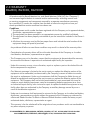
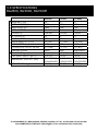
ELECTRIC GENERATORS
BG2800
BG5000
BG7000E
375
OI-B09052
12/2013
ANNAGEM BLVD., MISSISSAUGA, ONTARIO, CANADA, L5T 3A7, 905-364-4200 FAX 905-364-4201
03
200 COMMERCE DR, FREEHOLD, NEW JERSEY, 07728, 732-566-5400 FAX 732-566-5444
07/2014
Bartell Morrison (USA) LLC
Bartell Morrison (USA) LLC
375 Annagem Blvd.
200 Commerce Drive,
Mississauga, Ontario, Canada
Freehold, New Jersey, USA
L5T 3A7
07735
Toll Free (N.A.): (866) 501-1683
Toll Free: 888-999-1570
Phone: (905) 364-4200
Phone: (732) 566-5400
Facsimile: (905) 364-4201
Facsimile: (732) 566-5444
www.bartellmorrison.com
www.bmiamerica.com
ORIGINAL LANGUAGE PARTS MANUAL FOR
ELECTRONIC GENERATOR
© 2013 Bartell Morrison Inc.
No part of this work may be reporduced or transmitted in any
form or by any means, electronic, or mechanical, including
photocopying and recording, or by any information storage or
retrieval system without the prior written permission of Bartell
Morrison Inc, unless such copying is permitted by federal
copyright laws.
Address inquiries or reference permission care of:
Bartell Morrison Inc.,
375 Annagem Blvd.,
Mississauga, Ontario,
Canada, L5T 3A7
Revision
Date
00
01
02
03
12/2013
05/2014
06/2014
07/2014
Description
Initial Release
Parts list, and electrical and parts diagrams updated.
Address Update
Specifications Edit
Approved By:
AL
AL
AL
AL
375 ANNAGEM BLVD., MISSISSAUGA, ONTARIO, CANADA, L5T 3A7, 905-364-4200 FAX 905-364-4201
200 COMMERCE DR, FREEHOLD, NEW JERSEY, 07728, 732-566-5400 FAX 732-566-5444
OPERATOR’S MANUAL
BG2800, BG5000, BG7000E
1.0 INTRODUCTION
1.1 EQUIPMENT USE AND CARE
1.2 SAFETY FEATURES
2.0 WARRANTY
3.0 SPECIFICATIONS
4.0 SAFETY
5.0 PARTS AND COMPONENTS
6.0 INSPECTION
6.1 LUBE OIL
6.2 FUEL
6.3 AIR CLEANER
7.0 STARTING THE GENERATOR
8.0 ELECTRICAL CONNECTION
8.1 GENERATOR GROUNDING
8.2 TYPICAL ELECTRICAL CONSUMPTION
8.3 APPLIANCE START-UP
8.4 AC APPLICATION
8.5 DC APPLICATION
9.0 STOPPING THE GENERATOR
10.0 REGULAR INSPECTION AND MAINTENANCE
10.1 ENGINE OIL REPLACEMENT
10.2 SPARK PLUG CLEANING
11.0 STORAGE
11.1 STORAGE PREPARATION
11.2 CLEANING
11.3 FUEL
11.4 DRAINING THE FUEL TANK AND CARBURETOR
11.5 ENGINE OIL
11.6 STORAGE PRECAUTIONS
11.7 REMOVAL FROM STORAGE
12.0 TROUBLESHOOTING
12.1 STARTING FAILURE
12.2 APPLIANCE DOES NOT WORK
13.0 ELECTRICAL DIAGRAMS
13.1 BG2800, BG5000 ELECTRICAL DIAGRAM
13.2 BG7000E ELECTRICAL DIAGRAM
14.0 ASSEMBLY DRAWINGS
15.0 PARTS LIST
4
4
5
6
7
9
10
11
12
13
14
14
15
16
16
17
18
19
20
21
21
21
22
22
22
23
24
25
26
27
28
30
1.0 INTRODUCTION
BG2800, BG5000, BG7000E
Your New Bartell Electric Generator
The machines are portable Bartell Electric Generators powered by a four-stroke gasoline engine with
120/240VAC, 60Hz and 12VDC output. The Bartell Electric generators are suitable as temporary
power supply. They have been designed to meet ETL safety standards and current EPA air quality regulations.
1.1 Equipment Use and Care
Bartell Electric Generator is designed for use as a portable temporary power supply. It should be operated at all times in accordance with the instructions detailed in this manual:
- Use of this equipment for any purpose other than that stated within creates the risk of personal injury and/or property damage.
Any modifications to the equipment must be performed by the manufacturer or an authorized dealer and must be authorized in advance by the manufacturer.
The equipment should be serviced, cleaned and stored as detailed by this manual.
Failure to follow these guidelines may result in the warranty being void. The manufacturer of this equipment cannot be held responsible for any damages resulting from misuse, abuse, or neglect.
1.2 Safety Features
Bartell Electric Generators are equipped with safety guards and electrical protection in accordance with
North American and International standards.
NEVER attempt to disable or circumvent these safety devices. They are present for the
operator’s protection and any tampering will result in substantial risk to the operator and
all present in the vicinity. If the generator’s safety devices have been tampered with, do not
use the equipment. Immediately contact your sales representative to obtain replacement
parts or return the generator to your dealer for repairs.
375 ANNAGEM BLVD., MISSISSAUGA, ONTARIO, CANADA, L5T 3A7, 905-364-4200 FAX 905-364-4201
200 COMMERCE DR, FREEHOLD, NEW JERSEY, 07728, 732-566-5400 FAX 732-566-5444
4
2.0 WARRANTY
BG2800, BG5000, BG7000E
All products sold by Bartell Morrison Inc. and Bartell Morrison (USA) LLC (the “Company”)
are warranted against defects in material and/or worksmanship; excluding normal wear
on wearing components and components covered by a separate manufacturers warranty,
for a period of 12 months for machine from the date of sale to the original end user purchaser provided that certain conditions have been met.
Conditions:
1. The equipment serial number has been registered with the Company or its approved dealers,
distributors, representatives or agents.
2. The equipment has been operated in an appropriate manner by qualified individuals.
3. The equipment has been properly maintained as per the instructions included in the Owner’s
Manual.
4. All claims for warranty must be filed on proper forms and include the serial number of the
equipment along with proof of purchase.
Any evidence of failure to meet these conditions may result in a denial of the warranty claim.
- Consideration of warranty claims will be at the sole discretion of the Company, or its authorized dealers, distributors, representatives or agents.
- The Company may, at its discretion, request that the equipment to be considered for warranty
be returned at the owner’s expense to an authorized repair facility for inspection.
- Under this warranty we may, at our discretion, repair or replace a part or the whole of the defective component or equipment.
- Our Warranty coverage is limited to the cost to repair or replace the defective portion of the
equipment and a reasonable (as determined by the Company) amount of labour to conduct
the repair or replacement. Under no circumstances shall the Company be liable for any additional or exceptional costs beyond the cost to repair or replace the defective portion of the
equipment. The Company shall not be held accountable for; costs associated with travel to
inspect or repair defective equipment, costs for transporting defective equipment to or from
an authorized repair facility, costs incurred to repair or replace the defective equipment at any
facility other than one authorized by the Company or ancillary damage caused by or as a
result of the defective equipment.
- Under no circumstances shall equipment be returned to the Company or its authorized dealers,
distributors, representatives or agents without the approval of the Company as evidenced by
a Returned Goods Number. To obtain a Returned Goods Number contact the factory or your
authorized dealer, distributor, representative or agent.
- This warranty is for the sole benefit of the original end user purchaser and is not transferable to
any other company or person.
375 ANNAGEM BLVD., MISSISSAUGA, ONTARIO, CANADA, L5T 3A7, 905-364-4200 FAX 905-364-4201
200 COMMERCE DR, FREEHOLD, NEW JERSEY, 07728, 732-566-5400 FAX 732-566-5444
5
UNIT
ENGINE
GENERATOR
3.0 SPECIFICATIONS
BG2800, BG5000, BG7000E
FREQUENCY (Hz)
RATED OUTPUT (W)
MAX OUTPUT (W)
RATED CURRENT
VOLTAGE (V)
DC OUTPUT (V)
ENGINE MODEL
DISPLACEMENT cu. in. (cc)
ENGINE SPEED (rpm)
CONTINUOUS OUTPUT hp (kW)
STARTING SYSTEM
OIL CAPACITY gal. (L)
FUEL TANK CAPACITY gal. (L)
DIMENSION L x W x H in. (mm)
NET WEIGHT lb. (kg)
BG2800
60
2500
2800
10.4 A
120/240
12
200
12 (196)
3600
4.9 (3.66)
Recoil
0.16 (0.6)
3.96 (15)
25.6x18x18.9
(650x458x480)
99 (45)
BG5000
60
4500
5000
18.8 A
120/240
12
390
23.7 (389)
3600
9.9 (7.37)
Recoil
0.37 (1.4)
6.6 (25)
29.3x21x23.2
(745x535x590)
172 (78)
BG7000E
60
6500
7000
27.1 A
120/240
12
420
25.6 (420)
3600
10.7 (8.0)
Recoil/Electric
0.37 (1.4)
6.6 (25)
29.3x21x23.2
(745x535x590)
194 (88)
375 ANNAGEM BLVD., MISSISSAUGA, ONTARIO, CANADA, L5T 3A7, 905-364-4200 FAX 905-364-4201
200 COMMERCE DR, FREEHOLD, NEW JERSEY, 07728, 732-566-5400 FAX 732-566-5444
6
4.0 SAFETY
BG2800, BG5000, BG7000E
The instructions provided in this manual are done so to ensure the operator’s safety as well
as that of others, the equipment, and the job site. Failure to abide by these guidelines can
lead to serious personal injury and even death. The operator and any service personnel
should read and understand the entire manual before working with or servicing any Bartell
Electric Generator.
- The Electric Generator manual should be kept at all times in a place that is accessible to any persons working with the machine. Replacement manuals are available
from Bartell or from your local dealer.
- Only use parts and attachments supplied or approved by your Bartell equipment
manufacturer. The consequences of modifying the design of this equipment can include personal
injury, equipment failure, and voiding your warranty. If you are unsure about a repair or an apparent malfunction, contact your Bartell dealer or the phone contacts at the bottom of each page of this
manual.
- Technical service bulletins, user’s manual updates, and other information are posted
on the Bartell website: http://www.bartellmorrison.com
Check this website periodically for updates or other potentially useful information
about your equipment.
- NEVER use a Bartell Electric Generator in an enclosed space with poor air flow, such as
a basement or small room. The gasoline engine produces, among other things, toxic
carbon monoxide gas. Without proper ventilation, this gas will build up and cause
health effects such as organ damage and death to anyone in the vicinity.
- NEVER operate the Bartell Electric Generator in a wet environment.
- NEVER connect the Bartell Electric Generator to a power circuit if the commercial power supply is not
disconnected.
- ALWAYS keep 3 ft. (1m) away from flammable materials.
- The Generator operator should always be lucid and aware of his/her surroundings. NEVER operate
the Generator while under the influence of drugs, alcohol, fatigue, sickness, hangover, extreme depression, emotional distraction, or medications/substances that may affect motor skills or judgment.
- ALWAYS wear the appropriate personal protective equipment (PPE) while operating a Bartell Electric
Generator. This includes (but is not limited to) proper clothing, hearing protection and protective footwear. Other safety gear may be job-site appropriate.
- NEVER leave the equipment unattended while running.
375 ANNAGEM BLVD., MISSISSAUGA, ONTARIO, CANADA, L5T 3A7, 905-364-4200 FAX 905-364-4201
200 COMMERCE DR, FREEHOLD, NEW JERSEY, 07728, 732-566-5400 FAX 732-566-5444
7
4.0 SAFETY
BG2800, BG5000, BG7000E
- ALWAYS ensure that the operators have been properly trained prior to using the equipment.
- Children and small animals should NEVER be present in the work area during operation of a Bartell
Electric Generator.
- ALWAYS check your Bartell Electric Generator for loose or missing nuts and bolts
before starting. Tighten any loose fasteners and replace missing or broken parts.
- Perform all routine maintenance as described within this manual. Failure to do so
will void your warranty and will eventually result in premature equipment failure.
- NEVER perform maintenance on a running piece of equipment. Shut down the engine and allow it to
cool before servicing a Bartell Electric Generator, including mechanical work or lubrication.
- ALWAYS replace missing, damaged or unclear safety labels to ensure operator awareness and safety.
- NEVER operate a Bartell Electric Generator with missing or damaged safety guards. Replace immediately with appropriate Bartell parts.
- NEVER wear loose fitting clothing or jewelry around rotating equipment as it may become entangled
in the machinery, resulting in serious injury.
- NEVER fuel a Bartell Electric Generator while the engine is running. Ensure the
engine has cooled sufficiently before refueling to avoid igniting gasoline fumes.
- ALWAYS refuel a Bartell Electric Generator in a well-ventilated area, away from
ignition sources such as sparks, flames, and lit cigarettes. Smoking while fuelling
the equipment may result in explosion.
- NEVER operate a Bartell Electric Generator in explosive environments such as those
where paint fumes, methane, natural gas, fine particulate, aerosol propellant, or
solvent fumes are present.
- NEVER smoke near a Bartell Electric Generator as stray gasoline fumes may ignite.
Operating a Bartell Electric Generator around an open flame may also result in
explosion.
- ALWAYS shut down the engine and allow it to cool before lifting or transporting a
Bartell Electric Generator.
- ALWAYS tie down a Bartell Electric Generator when being transported in a truck or on a flatbed.
Empty the fuel tank if transporting over long distances.
375 ANNAGEM BLVD., MISSISSAUGA, ONTARIO, CANADA, L5T 3A7, 905-364-4200 FAX 905-364-4201
200 COMMERCE DR, FREEHOLD, NEW JERSEY, 07728, 732-566-5400 FAX 732-566-5444
8
5.0 PARTS AND COMPONENTS INTRODUCTION
BG2800,
BG5000,
BG7000E INTRODUCTION
2. PARTS
AND COMPONENTS
Model:CL
(1)
(14)
(2)
(12)
(13)
(3)
(4)
(11)
(5)
(6)
(10)
(7)
(9)
(8)
(1)
Fuel tank
tank
(1) Fuel
(2)
Muffler
(2) Muffler
(3)
Earth terminal
terminal
(3) Earth
(4)
AC socket/plug
socket/plug
(4) AC
(5)
Carburetorthrottle
throttlelever
lever
(5) Carburetor
(6)
Recoil starter
(6) Starter
handle handle
(7) Fuel valve
(7) Fuel cock
(8) Air cleaner
(8) Air cleaner
(9) Pipe frame
(9) Pipe frame
(10) Spark plug
(10) Spark plug
(11) Fuel tank cap
(11) Fuel tank cap
(12) Breaker
(12) Breaker
(13) Oil gauge dipstick
(13) Oil
gauge
Dipstick
(14)
Starter
switch
(14) Starter
switch
(15)
AC protector
(15) AC protector
Model:C
(11)
(1)
(2)
(14)
(8)
(4)
(15)
(Non-frame model)
-3375 ANNAGEM BLVD., MISSISSAUGA, ONTARIO, CANADA, L5T 3A7, 905-364-4200 FAX 905-364-4201
200 COMMERCE DR, FREEHOLD, NEW JERSEY, 07728, 732-566-5400 FAX 732-566-5444
9
6.0 INSPECTION
BG2800, BG5000, BG7000E
4. INSPECTION BEFORE OPERATION
4-1. Lube
Lube Oil
6.1
Oil
Always
a level
Always check
check the
the oil
oil level
level on
before
start
surface
before
starting.on a level place.
The stooping
generator
① Turn
fillter gauge
(dipstick)
Turn
outout
thethe
oil oil
dipstick
and wipe
it
withand
a clean
cloth.
clean it with a clean cloth.
② Insert
the dipstick
back without
Insert
the dipstick
back without
screwing
in, pull
it out,
screw
in,and
and check
check the
the level.
oil level.
③ In the case that the oil level is below
In the case that the oil is low, refill it until
lower
mark the
of the
dipstick,
the
the the
level
reaches
upper
markrefill
on the
oil to the upper mark.
dipstick.
④ Reinstall the dipstick.
Reinstall the dipstick when complete.
-7-
375 ANNAGEM BLVD., MISSISSAUGA, ONTARIO, CANADA, L5T 3A7, 905-364-4200 FAX 905-364-4201
200 COMMERCE DR, FREEHOLD, NEW JERSEY, 07728, 732-566-5400 FAX 732-566-5444
10
6.0 INSPECTION
BG2800, BG5000, BG7000E
4-2. Fuel
Fuel
6.2
① Open
fuel
tank
cap.
Open
thethe
fuel
tank
cap.
② Check
fuel
level,
and
refuel
if necessary.
Check
thethe
fuel
level
and
refuel
if necessary.
③ Refuel
up to
the shoulder
thefilter.
fuel fillter.
Fill
up to the
shoulder
of theoffuel
④ Reinstall
tank
cap.
Reinstall
thethe
fuelfuel
tank
cap
when complete.
375 ANNAGEM BLVD., MISSISSAUGA, ONTARIO, CANADA, L5T 3A7, 905-364-4200 FAX 905-364-4201
200 COMMERCE DR, FREEHOLD, NEW JERSEY, 07728, 732-566-5400 FAX 732-566-5444
-811
6.0 INSPECTION
BG2800, BG5000, BG7000E
4-3. Air
Air Cleaner
6.3
Cleaner
① Loosen the clip and remove the air cleaner housing. (For model: CL)
Loosen the clip and remove the air cleaner housing.
Loosen the wing-nut and remove the air cleaner cover. (For model: C)
(Model: CL)
( Model: C)
② Loosen the wing-nut and
washer, and remove the
element.
③ Separate the primary and
secondary element.
④ Wash
⑤ Tap
Tap the
the element
elementor
oruse
use
Squeeze
Squeeze
compressed
air to
to blow
compress air
blow
from
the
inside.
from inside.
Engine Oil
Soak
(Model: CL)
( Model: C)
375 ANNAGEM BLVD., MISSISSAUGA, ONTARIO, CANADA, L5T 3A7, 905-364-4200 FAX 905-364-4201
200 COMMERCE DR, FREEHOLD, NEW JERSEY, 07728, 732-566-5400 FAX 732-566-5444
12
-9-
7.0 STARTING THE GENERATOR
BG2800, BG5000, BG7000E
5. STARTING THE GENERATOR
5-1. Remove all the loads from
5-2. Set the fuel cock to
ACsocket
andfrom
switch
Remove
all loads
theoff
socket
and the
switch
off the breaker.
BREAKER.
Set the
fuelposition.
valve to the
“ON”
“ON” position.
ON
ON
(Model: CL, C)
5-3. Push the choke lever to
Push“CLOSE”
the chokeposition.
lever to the
“CLOSE” position.
(Model: CL)
(Model: C)
5-4. Turn the engine swithch
Turnto
the
engine
or key switch
“ON”
position.
to the “ON” position.
ON
ON
OFF
OFF
(Model: CL)
(Model: C)
5-5. Pull the starter handle until
resistance is felt, then pull it
Pull out
out the
recoil starter
swiftly
from handle
original
until position.
resistance is felt, then pull it
out swiftly from its original position.
The BG7000E is an electric
(Model: CL)
(Model: C)
start model. Continue to turn
the key to “START” and release
when
the generator
starts.
If
5-6. Once
the generator
starts,
the battery is too weak to start,
gradually turn the chock
the recoil start may be used.
lever to “ON” position.
Once the generator starts,
gradually turn the choke lever
to the “OPEN” position.
(Model: CL)
(Model: C)
-10375 ANNAGEM
BLVD., MISSISSAUGA, ONTARIO, CANADA, L5T 3A7, 905-364-4200 FAX 905-364-4201
200 COMMERCE DR, FREEHOLD, NEW JERSEY, 07728, 732-566-5400 FAX 732-566-5444
13
8.0 ELECTRICAL CONNECTIONS
BG2800, BG5000, BG7000E
6. ELECTRIC CONNECTING
CAUTION
keep the
the generator
generatorininthe
thebest
bestrunning
running
and
electric
condition,
please
★ To
To keep
and
electric
condtion,
please
obey
refer
to the following:
the follows:
8.1
Generator
6-1.
Ground the Grounding
generator to prevent electric shock:
Ground the generator to prevent electric shock:
(Model: CL, C)
8.2 Typical Electrical Consumption
Refer
to the
electrical
consumption
of other
appliances:
6-2. Refer
some
appliance
for electric
consumption:
Wattage
Type
Sample
Appliance
Starting Rated
Electric bulb
or heater
Day
light
Daylight
lamp
lamp
Appliance
Electric
bulb
X1
Rated
Electric
bulb
100VA(W) 100VA(W)
X1
TV
X2
Starting
X1.5
Day light lamp
100W
40W
40W Day
Fluorescent
light
Lamp lamp
80VA(W) 60VA(W)
Refrigerator
Motor Drive
X3-5
X2
750W
Electric fan Refrigerator
150W
450-750 300VA(W)
VA
-11375 ANNAGEM BLVD., MISSISSAUGA, ONTARIO, CANADA, L5T 3A7, 905-364-4200 FAX 905-364-4201
200 COMMERCE DR, FREEHOLD, NEW JERSEY, 07728, 732-566-5400 FAX 732-566-5444
14
8.0 ELECTRICAL CONNECTIONS
BG2800, BG5000, BG7000E
8.3 Appliance Start-Up
6-3.
the generator
supply
moretothan
appliances,
be sure to
start
them
If
theIfgenerator
is to is
supply
power
more2 than
two appliances,
start
them
one
by one
with
the
highest
current
first.
one by one with the highest current first.
1 ON
6-3. If the generator is supply more than 2 appliances, be sure to start them
one by one with the highest current first.
1 ON
ON
2
ON
3
ON
2
CAUTION:NEVER
Do not connect the generator to 3home power circuit. When this
connect the generator to a home power circuit without a
ON
connection transfer
is necessary,
beAsure
that switch
a skilled
the job. Improper
switch.
transfer
is electrician
required bydoes
the National
Electric
for the
anygenerator
connection
of home
powerpower
to a home.
connecting Code
between
and
circuit may cause damage of
the generator, and even fire accident.
A transfer switch prevents back-feed, which occurs when power goes
CAUTION:
Do not connect the generator to home power circuit. When this
back down the utility lines. Back-feed has the potential to cause a fire
connectionand
is necessary,
suregenerator.
that a skilled
electrician
does the can
job. elecImproper
OK be the
can damage
Even
worse,Forbidden
back-feed
connectingtrocute
between
generator working
and home
circuit
may cause
anythe
technicians
onpower
the lines,
causing
injurydamage
or evenof
death.
the generator,
and even fire accident.
Forbidden
OK
OK
OK
375 ANNAGEM BLVD., MISSISSAUGA, ONTARIO, CANADA, L5T 3A7, 905-364-4200 FAX 905-364-4201
200 COMMERCE DR, FREEHOLD, NEW JERSEY, 07728, 732-566-5400 FAX 732-566-5444
15
-12-
8.0 ELECTRICAL CONNECTIONS
BG2800, BG5000, BG7000E
8.4
6-4.AC
AC Application
electric connecting
1. Starting
generator.
1.
Start thethe
generator.
2. Connecting the appliances.
(Model: CL, C)
3. Turn
pushthe
down
Ac protector.
3.
Turn on
on the
theBREAKER
breaker ororpush
AC the
protector
down.
ON
6-5.DC
DC Application
Application
8.5
TheDC
DCterminal
terminal
may
used
charging
automotive-type
batteries
The
may
bebe
used
forfor
charging
12V12V
automotive-type
batteries
only.only.
① When using automotive-type batteries with battery cables, be sure to
1.When using automotive-type batteries with cables, be sure to disconnect the negative cable
disconnect
minus
pole battery cable from the battery before charging.
from
the batterythe
before
charging.
② Connect the charging cable to the battery terminals and the DC terminal of
2.Connect the charging cable to the battery terminals and the DC terminal of the generator.
generator.
● Connect
positive
battery
terminal
to positive
the positive
generator
terminal.
Connect
thethe
positive
battery
terminal
to the
generator
terminal.
● Do not reverse the charging cables, or serious damage to the generator
Doand/or
not reverse
themay
charging
Battery
occur.cables, or serious damage to the generator and/or battery may
occur.
● Do not allow the free ends of the cable to touch each other, if this occur, it will
theends
battery.
Dobe
notshort
allowcircuit
the free
of the cables to touch, as it can short circuit the battery.
● When a large capacity battery is charged, excessive current flows (the value
When
a large
capacityon
battery
is charged, condition),
excessive current
flows
on the disvaries
depending
the discharged
and the
fuse(depending
for DC current
charge condition), can cause the fuse for the DC current to burn out.
will burn out.
produce
explosive
gases.
sparks,
and cigarettes
well
③ Batteries
produce
explosive
gases.
KeepKeep
sparks,
flamesflames
and cigarettes
well away.
3.Batteries
away.
4.To prevent the possibility of creating a spark near the battery, always connecting charging
④ To prevent the possibility of creating a spark near the battery, always connect
cables to the battery first and then only to the generator. When disconnecting, remove the
charging
toend
battery
cables
at the cables
generator
first. first and only then to the generator. When
disconnecting, you should disconnect the cables at the generator first.
5.Charge the battery in a well ventilated place.
⑤ Charge the battery in a well ventilated place.
charging,
remove
the cap
of cell
the battery.
Discontinue
charging if the
6.Before
charging,
remove
the from
cap each
from cell
each
of the battery,
Discontinue
⑥ Before
electrolyte temperature exceeds 45C.
charging if the electrolyte temperature exceeds 45°C.
375 ANNAGEM BLVD., MISSISSAUGA, ONTARIO, CANADA, L5T 3A7, 905-364-4200 FAX 905-364-4201
-13200 COMMERCE DR, FREEHOLD, NEW JERSEY, 07728, 732-566-5400 FAX 732-566-5444
16
9.0 STOPPING THE GENERATOR
BG2800, BG5000, BG7000E
7. STOPPING THE GENERATOR
7-1.
off the
Breaker.
TurnTurn
off the
breaker.
OFF
(Model: CL, C)
7-2.
off the
engine
switch.
TurnTurn
off the
engine
switch.
OFF
OFF
(Model: CL)
(Model: C)
7-3.
off the
cock.
TurnTurn
off the
fuelfuel
valve.
OFF
OFF
(Model: CL)
(Model: C)
NOTE:
emergency,
turn the engine
switch
“OFF”toto
stoptothe
generator.
NOTE: InInthe
case of an emergency,
turn the
enginetoswitch
“OFF”
stop
the generator.
WARNING Never
stopping
the generator
at speed
high speed
heavy
Never stop
the generator
at high
underunder
a heavy
load.load,
This
can result inthe
damage.
otherwise,
damage will result.
-14375 ANNAGEM
BLVD., MISSISSAUGA, ONTARIO, CANADA, L5T 3A7, 905-364-4200 FAX 905-364-4201
200 COMMERCE DR, FREEHOLD, NEW JERSEY, 07728, 732-566-5400 FAX 732-566-5444
17
10.0 REGULAR INSPECTION AND MAINTENANCE
BG2800, BG5000, BG7000E
8. REGULAR INSPECTION AND MAINTENANCE
CAUTION
Daily
and regular
inspection
is important
to assureto
safe,
proper,
andproper
long-term
Daily
and regular
inspection
is important
assure
safe,
and
operation of the generator. Refer to the provided regular inspection table when
long-termanoperation
the
generator. Refer to the regular inspection
conducting
inspectionof
and
maintenance.
table when conducting inspection and maintenance.
Inspection
Replace
Cleaning
20hrs or
Daily check first month
50hrs
or every
3 month
Adjustment
100hrs
or every
6 month
300hrs
or every
1year
Refer page
Lube oil
check
P.5
Replace
engine oil
P.14
Air cleaner
check
P.7
Air cleaner
wash
P.7
Fuel fillter
cup
P.16
Fuel fillter
P.16
Spark plug
P.15
Value
Valve
–
Cylinder
cover wash
–
clearance
Fuel tank
wash
Every 2 years or when necessary.
–
-15-
375 ANNAGEM BLVD., MISSISSAUGA, ONTARIO, CANADA, L5T 3A7, 905-364-4200 FAX 905-364-4201
200 COMMERCE DR, FREEHOLD, NEW JERSEY, 07728, 732-566-5400 FAX 732-566-5444
18
10.0 REGULAR INSPECTION AND MAINTENANCE
BG2800, BG5000, BG7000E
8-1. Engine oil replacement
10.1
Engine Oil Replacement
① Loosen the oil drain plug
② Drain off the engine oil in the
1. Loosen
the oil drain plug.
crankshaft.
2. Drain the oil and remove the
and dipstick.
dipstick.
③ Screw
Screw in
the
3.
onand
andtighten
tighten
the
drain
plug
with
seal
washer.
drain with seal washer.
④ Fill
Filling
the
engineoiloiltotothe
the
4.
with
engine
upper
level
onlevel.
the dipstick.
upper
plug
⑤ Reinstall
Reinstallthe
thedipstick.
dipstick.
5.
Recommended Engine Oil:
4-stroke gasoline engine oil API Service Classification
Recommended Engine oil:
SAE 10W-30 equivalent to SJ or better.
4-stroke gasoline engine oil SF, SF from
In Frigid Temperature (below -15C):
API Service Classification or SAE 10W-30
4-stroke gasoline engine oil API Service Classification
to SGtoClass.
SAE equivalent
5W-30 equivalent
SJ or better.
In Frigid Ambience Temperature
(below -15°C)
SE.SF from API Service Classification or
SAE5W-30 equivalent to SG Class.
375 ANNAGEM BLVD., MISSISSAUGA, ONTARIO, CANADA, L5T 3A7, 905-364-4200 FAX 905-364-4201
-16-COMMERCE DR, FREEHOLD, NEW JERSEY, 07728, 732-566-5400 FAX 732-566-5444
200
19
10.0 REGULAR INSPECTION AND MAINTENANCE
BG2800, BG5000, BG7000E
10.2 Spark Plug Cleaning
1. Remove spark plug cap.
3. Clean away any carbon build-up.
2. Dismantle the spark plug.
4. Measure the electrode clearance/gap.
5. Reinstall the spark plug and cap.
375 ANNAGEM BLVD., MISSISSAUGA, ONTARIO, CANADA, L5T 3A7, 905-364-4200 FAX 905-364-4201
200 COMMERCE DR, FREEHOLD, NEW JERSEY, 07728, 732-566-5400 FAX 732-566-5444
20
11.0 STORAGE
BG2800, BG5000, BG7000E
Storing Your Generator
11.1 Storage Preparation
Proper storage preparation is essential for keeping your engine trouble-free and looking
good. The following steps will help to keep rust and corrosion from impairing your engine’s function and appearance, and will make the engine easier to start when you use
it again.
11.2 Cleaning
If the engine has been running, allow it to cool for at least half an hour before cleaning.
Clean all exterior surfaces, touch up any damaged paint, and coat other areas that may
rust with a light film of oil.
NOTICE
Using a garden hose or pressure washing equipment can force water into the air cleaner
or muffler opening. Water in the air cleaner will soak the air filter, and water that passes
through the air filter or muffler can enter the cylinder, causing damage.
11.3 Fuel
NOTICE
Depending on the region where you operate your equipment, fuel formulations may
deteriorate and oxidize rapidly. Fuel deterioration and oxidation can occur in as little as
30 days and may cause damage to the carburetor and/or fuel system. Please check with
your servicing dealer for local storage recommendations.
Gasoline will oxidize and deteriorate in storage. Deteriorated gasoline will cause hard
starting, and it leaves gum deposits that clog the fuel system. If the gasoline in your
engine deteriorates during storage, you may need to have the carburetor and other fuel
system components serviced or replaced.
The length of time that gasoline can be left in your fuel tank and carburetor without causing functional problems will vary with such factors as gasoline blend, your storage temperatures, and whether the fuel tank is partially or completely filled. The air in a partially
filled fuel tank promotes fuel deterioration. Very warm storage temperatures accelerate
fuel deterioration. Fuel deterioration problems may occur within a few months, or even
less if the gasoline was not fresh when you filled the fuel tank.
Fuel system damage or engine performance problems resulting from neglected storage
preparation are not covered under the Distributor’s Limited Warranty.
375 ANNAGEM BLVD., MISSISSAUGA, ONTARIO, CANADA, L5T 3A7, 905-364-4200 FAX 905-364-4201
200 COMMERCE DR, FREEHOLD, NEW JERSEY, 07728, 732-566-5400 FAX 732-566-5444
21
11.0 STORAGE
BG2800, BG5000, BG7000E
11.4 Draining the Fuel Tank and Carburetor
1. Move the fuel valve lever to the OFF position.
2. Place an approved gasoline container below the carburetor, and use a funnel to avoid
spilling.
3. Remove the carburetor drain bolt and gasket. Remove the sediment cup and o-ring,
then move the fuel valve lever to the ON position.
4. After all the fuel has drained into the container, reinstall the drain bolt, gasket, sediment
cup and o-ring. Tighten the drain bolt and sediment cup securely.
11.5 Engine Oil
1. Change the engine oil (see page 9)
2. Remove the spark plug (see page 12).
3. Pour one to two teaspoons (5-10 cc) of clean engine oil into the cylinder.
4. Pull the starter rope several times to distribute the oil in the cylinder.
5. Reinstall the spark plug.
6. Pull the starter rope slowly until resistance is felt and the notch on the start pulley aligns
with the hole at the top of the recoil starter cover. This will close the valves so moisture
cannot enter the engine cylinder. Return the starter rope gently.
11.6 Storage Precautions
If your engine will be stored with gasoline in the fuel tank and carburetor, it is important
to reduce the hazard of gasoline vapor ignition. Select a well ventilated storage area
away from any appliance that operates with a flame, such as a furnace, water
heater, or clothes dryer. Also avoid any area with a spark producing electric motor, or
where power tools are operated.
If possible, avoid storage areas with high humidity, because that promotes rust and corrosion.
Keep the engine level in storage. Tilting can cause fuel or oil leakage.
With the engine and exhaust system cool, cover the engine to keep out dust. A hot
engine and exhaust system can ignite or melt some materials. Do not use sheet plastic
as a dust cover. A nonporous cover will trap moisture around the engine, promoting rust
and corrosion.
If equipped with a battery for electric starter types, recharge the battery once a month
while the engine is in storage. This will help to extend the service life of the battery.
375 ANNAGEM BLVD., MISSISSAUGA, ONTARIO, CANADA, L5T 3A7, 905-364-4200 FAX 905-364-4201
200 COMMERCE DR, FREEHOLD, NEW JERSEY, 07728, 732-566-5400 FAX 732-566-5444
22
11.0 STORAGE
BG2800, BG5000, BG7000E
11.7 Removal from Storage
Check your engine as described in the INSPECTION section of this manual.
If the fuel was drained during storage preparation, fill the tank with fresh gasoline. If you
keep a container of gasoline for refueling, be sure it contains only fresh gasoline. Gasoline oxidizes and deteriorates over time, causing hard starting.
If the cylinder was coated with oil during storage preparation, the engine will smoke
briefly at startup. This is normal.
375 ANNAGEM BLVD., MISSISSAUGA, ONTARIO, CANADA, L5T 3A7, 905-364-4200 FAX 905-364-4201
200 COMMERCE DR, FREEHOLD, NEW JERSEY, 07728, 732-566-5400 FAX 732-566-5444
23
12.0 TROUBLESHOOTING
BG2800, BG5000, BG7000E
10. TROUBLES SHOOTING
12.1
Failure
10-1. Starting
Starting failure
① Is the engine switch at “ON” position?
(Model: CL)
(Model: C)
② Is the oil level too low?
③ Is there enough the fuel?
④ Check the spark plug.
(Model: CL)
OK
(Model: C)
MAINTENACE
-20375 ANNAGEM BLVD., MISSISSAUGA, ONTARIO, CANADA, L5T 3A7, 905-364-4200 FAX 905-364-4201
200 COMMERCE DR, FREEHOLD, NEW JERSEY, 07728, 732-566-5400 FAX 732-566-5444
24
① Check the appliance device.
12.0 TROUBLESHOOTING
BG2800, BG5000, BG7000E
12.2 Appliance does not work.
10-2. Appliance do not work
ON
② Is the BREAKER at “ON” position?
OFF
Checkthe
theappliance
appliance device.
device.
1.①
Check
(Model: CL)
③ Is the AC protector reset at “ON” position?
ON
thebreaker
BREAKER
at “ON”
position?
2.②
Is Is
the
in the
“ON” position?
OFF
(Model: C)
(Model: CL)
OK
MAINTENACE
③ Is the AC protector reset at “ON” position?
(Model: C)
OK
-21-
MAINTENACE
375 ANNAGEM BLVD., MISSISSAUGA, ONTARIO, CANADA, L5T 3A7, 905-364-4200 FAX 905-364-4201
-21200 COMMERCE DR, FREEHOLD, NEW JERSEY, 07728, 732-566-5400 FAX 732-566-5444
25
13.0 ELECTRICAL DIAGRAM
BG2800, BG5000, BG7000E
13.1 BG2800, BG5000 Electrical Diagram
375 ANNAGEM BLVD., MISSISSAUGA, ONTARIO, CANADA, L5T 3A7, 905-364-4200 FAX 905-364-4201
200 COMMERCE DR, FREEHOLD, NEW JERSEY, 07728, 732-566-5400 FAX 732-566-5444
26
13.0 ELECTRICAL DIAGRAM
BG2800, BG5000, BG7000E
13.2 BG7000E Electrical Diagram
375 ANNAGEM BLVD., MISSISSAUGA, ONTARIO, CANADA, L5T 3A7, 905-364-4200 FAX 905-364-4201
200 COMMERCE DR, FREEHOLD, NEW JERSEY, 07728, 732-566-5400 FAX 732-566-5444
27
THIS PAGE HAS BEEN INTENTIONALLY LEFT BLANK
375 ANNAGEM BLVD., MISSISSAUGA, ONTARIO, CANADA, L5T 3A7, 905-364-4200 FAX 905-364-4201
200 COMMERCE DR, FREEHOLD, NEW JERSEY, 07728, 732-566-5400 FAX 732-566-5444
BG2800, BG5000, BG7000E
ASSEMBLY DRAWINGS AND PARTS
LIST
375 ANNAGEM BLVD., MISSISSAUGA, ONTARIO, CANADA, L5T 3A7, 905-364-4200 FAX 905-364-4201
200 COMMERCE DR, FREEHOLD, NEW JERSEY, 07728, 732-566-5400 FAX 732-566-5444
14.0 ASSEMBLY DRAWINGS
BG2800, BG5000, BG7000E
375 ANNAGEM BLVD., MISSISSAUGA, ONTARIO, CANADA, L5T 3A7, 905-364-4200 FAX 905-364-4201
200 COMMERCE DR, FREEHOLD, NEW JERSEY, 07728, 732-566-5400 FAX 732-566-5444
30
14.0 ASSEMBLY DRAWINGS
BG2800, BG5000, BG7000E
Following change:
Item no. Description
Quantity
Remark
FUEL TANK
58
Fuel tank cap(CARB approved)
1
Fuel Strainer
1
59
60
cancel
change to be this drawing
375 ANNAGEM
CANADA, L5Tchange
3A7, to905-364-4200
FAX 905-364-4201
61
Fuel tankBLVD.,
assembly MISSISSAUGA, ONTARIO,
1
be this drawing
200
COMMERCE
DR,
FREEHOLD,
NEW
JERSEY,
07728,
732-566-5400
FAX
732-566-5444
72
Clip
4
add 2 more
31
61-1
Joint
1
add
61-2
Fuel pip 4.5*8.5
600mm
add
15.0 PARTS LIST
BG2800, BG5000, BG7000E
Item No.
2
3
3-2
5
10
11
12
13
14
15
16
17
18
19
20
21
22
23
24-48
24
25
26
27
28
29
30
31
32
32
33
34
35
36
37
BG2800
Part No.
25001001
25001100
25001100-1
LMB08
LSB06012
TD06
PD06
25001004
LSB08020
TD08
PD08
25001005
LSB08020
TD08
PD08
LSB06012
TD08
PD08
3000ALT
25002001
LSB08025
25002002
30002100
25002003
PDC08
TDA08
LZA08230
LZA08230
30002200
30002004
25002005
LSB06145
25002300
BG5000
Part No.
38001001
38001101
38001101-1
LMB08
38001004
LSB08020
TD08
PD08
LSB08020
LSB08020
TD08
PD08
5000ALT
38002001
LSB08032
LSB05012
38002002
50002100
38002003
PDC010
TDA10
LZA10250
LZA10250
50002200
50002004
28002005
LSB06164
38002300
BG7000E
Part No.
38001001
38001101
38001101-1
LMB08
38001004
LSB08020
TD08
PD08
LSB08020
LSB08020
TD08
PD08
7500ALT
38002001
LSB08032
LSB05012
38002002
65002100
38002003
PDC010
TDA10
LZA10265
LZA10265
65002200
65002004
28002005
LSB06179
38002300
Description
Exhaust Gasket
Muffler Assembly
Heat Shroud
Flange HD Hex. Nut
Flange Head Bolt
Lock Washer
Flat Washer
Muffler Support A
Flange HD Hex. Bolt
Lock Washer
Washer
Muffler Support B
Flange HD Hex. Bolt
Lock Washer
Flat Washer
Flange HD Hex. Bolt
Lock Washer
Flat Washer
Alternator Assembly
Front Cover
Flange HD Hex. Bolt
Tapping Screw
Alternator Fan
Rotor
Ball Bearing
Washer
Lock Washer
Hex. Bolt
Hex. Bolt
Stator Assembly
Stator Protector
Rear Cover
Flange HD Hex. Bolt
Capacitor
375 ANNAGEM BLVD., MISSISSAUGA, ONTARIO, CANADA, L5T 3A7, 905-364-4200 FAX 905-364-4201
200 COMMERCE DR, FREEHOLD, NEW JERSEY, 07728, 732-566-5400 FAX 732-566-5444
32
Qty.
1
1
1
2
4
4
4
1
1
1
1
1
1
1
1
1
1
1
1
1
4
2
1
1
1
1
1
1
1
1
1
1
4
1
15.0 PARTS LIST
BG2800, BG5000, BG7000E
Item No.
38
42
42-2
45
46
47
48
49
49-1
49-2
49-3
49-4
49-5
49-6
49-7
49-8
49-9
49-10
49-11
49-12
49-13
49-14
49-15*
49-16*
49-17*
49-18*
49-19*
49-20*
49-21*
49-22*
49-23*
BG2800
Part No.
LSB05012
LSB05012
TD08
25002400
LSB05012
25002007
LSB05012
25003100
BG5000
Part No.
LSB05012
LSB05012
TD08
38002400
LSB05012
38002007
LSB06012
38003100
BG7000E
Part No.
LSB05012
LSB05012
TD08
38002400
LSB05012
38002007
LSB06012
38003100
425140001120 425140001120 425140001120
306000107100 306000107100 306000107100
450025030230 450025030230 450025030230
306000200312 306000200312 306000200312
431160000100 431160000100 431160000100
402060120160 402060120160 402060120160
306000108508 306000108508 306000108508
311020003700 311020003700 311020003700
422060000120 422060000120 422060000120
306000104908 306000104908 306000104908
411060350120 411060350120 411060350120
306290250204 306000105209 306000105209
306000100600 306000100600 306000100600
306290250104 306000105108 306000105108
-
-
306590250707
411060100120
211065900100
306000300600
306140310200
285061503000
285061504015
285061503001
285061504014
Description
Qty.
Flange HD Hex. bolt
Flange HD Hex. bolt
Lock Washer
Terminal Block
Flange Hd Hex. Bolt
End Cover
Flange HD Hex. Bolt
Frame
Locknut
Bearing
Pin
Wheel
Gasket
Bolt
Stabilizer Blade
Shock Absorber
Nut M6
Splint
Screw
Right Handle
Gum Sleeve
Left Handle
Battery Holder
Screw M6 x 10
Rubber Gasket
12AH Battery
Battery Fixer
Red Sheath
Red Battery Wire
Black Sheath
Black Battery Wire
* Only applicable for BG7000E
375 ANNAGEM BLVD., MISSISSAUGA, ONTARIO, CANADA, L5T 3A7, 905-364-4200 FAX 905-364-4201
200 COMMERCE DR, FREEHOLD, NEW JERSEY, 07728, 732-566-5400 FAX 732-566-5444
33
2
1
1
1
2
1
2
1
2
2
2
2
2
4
2
2
4
2
4
1
2
1
1
2
1
1
1
1
1
1
1
15.0 PARTS LIST
BG3000, BG5000, BG7000E
Item No.
50
51
52
53
53
54
55
56
58
60
61
61-1
62
62-2
63
63-2
63-3
63-4
63-5
64
65
66
67
68
69
69-2
69-3
70
70-2
70-3
71
72
BG2800
Part No.
LDA06012
LMA08
PDA08
25003200A
25003200B
TDA08
LSB08045
LMA08
25004001
25004003
25004100
61-1
25004004
62-2
25004005
LDA05010
LSB06012
PDB06
25004006
25004007
LMA06
69-2
69-3
25004200
25004008
25004009
BG5000
Part No.
LDA06012
LMA08
PDA08
25003200A
25003200B
TDA08
LSB08045
LMA08
25004001
25004003
38004100
61-1
25004004
62-2
25004005
LDA05010
LSB06012
PDB06
25004006
25004007
LMA06
69-2
69-3
25004200
38004008
25004009
BG7000E
Part No.
LDA06012
LMA08
PDA08
25003200A
25003200B
TDA08
LSB08045
LMA08
25004001
25004003
38004100
61-1
25004004
62-2
25004005
LDA05010
LSB06012
PDB06
25004006
25004007
LMA06
69-2
69-3
25004200
38004008
25004009
Description
Qty.
Pan HD Screw
4
Hex. Nut
4
Washer
4
Shock Absorber (engine)
2
Shock Absorber (alternator)
2
Lock Washer
8
Flange HD Hex. Bolt
2
Flange HD Hex. Nut
4
Fuel Tank Cap (CARB Approved)
1
Fuel Strainer
1
Fuel Tank Assembly
1
Joint Connection
1
Fuel LEVER
1
Fuel Line 4.5 x 8.5
600mm
Fuel Level Indicator
1
Fuel Indicator Cover
1
Top Gasket Cover
1
Glass
1
Gasket for Glass
1
Countersunk HD Screw
2
Flange HD Hex. Bolt
4
Washer
4
Collar
4
Rubber Grommet
4
Hex. Nut
4
Washer
4
Lock Washer
4
Fuel Valve
1
Special Nut
1
Rubber Seal with Flange
1
Fuel Pipe
1
Clip
4
375 ANNAGEM BLVD., MISSISSAUGA, ONTARIO, CANADA, L5T 3A7, 905-364-4200 FAX 905-364-4201
200 COMMERCE DR, FREEHOLD, NEW JERSEY, 07728, 732-566-5400 FAX 732-566-5444
34
15.0 PARTS LIST
BG3000, BG5000, BG7000E
Item No.
73
74
75
76
77
78
79
80
81
82
83
84
85
86
87
88
89
90
91
92
93
94
94-2
94-3
94-4
96
BG2800
Part No.
411050200120
5022001402201
305215003101
305160045301
305031252000
305031253004
BG5000
Part No.
411050200120
5022001402201
305215003101
305160045301
305031252000
305030002003
BG7000E
Part No.
411050200120
5022001402201
305215003101
305160045301
305031252000
305030002003
Description
Special Screw
Power Indicator Light
Engine On/Off Switch
Voltmeter
Socket
Socket
Ground Terminal (Assemble
with following parts)
402060220260 402060220260 402060220260 Bolt
422060000121 422060000121 422060000121 Nut
431060000103 431060000103 431060000103 Washer 6
432060000101 432060000101 432060000101 Spring Washer 6
434060000201 434060000201 434060000201 Serrated Gasket
305130000602 305130000602 305130000602 DC Socket
305200742001 305200742001 305200742001 Current Switch
305201120704 305201120704 305201120704 Fuse
305170530105 305170530205 305170530275 Circuit Breaker
305495000105 305495001602 305495001602 Rear Control Panel Cover
2050118090018 2050118080001 2050118080002 Control Panel Ass'y
20001001
39001001
39001001
Crankcase
YF254125
YF355208
YF355208
Oil Seal
ZCA6205
ZCA6207
ZCA6207
Ball Bearing
16001002
34001002
34001002
Governor Arm Shaft
16001003
24001003
24001003
Lock Pin
16001004
24001004
24001004
Washer
LSB10015
LSB12015
LSB12015
Drain Plug
16001005
24001005
24001005
Drain Plug Washer
16001100
34001100
34001100
Governor Kit
Governor Weight
Governor Weight Pins
Governor Gear
16001007
16001007
16001007
Governor Shaft Clip
375 ANNAGEM BLVD., MISSISSAUGA, ONTARIO, CANADA, L5T 3A7, 905-364-4200 FAX 905-364-4201
200 COMMERCE DR, FREEHOLD, NEW JERSEY, 07728, 732-566-5400 FAX 732-566-5444
35
Qty.
4
1
1
1
1
1
1
1
2
1
1
1
1
1
1
1
1
1
1
1
1
1
1
1
2
2
1
2
2
1
1
15.0 PARTS LIST
BG3000, BG5000, BG7000E
Item No.
97
98
100
101
102
103
104
105
106
107
109
110
111
112
113
114
115
116
117
119
119-2
119-3
119-4
119-5
119-6
119-7
120
121
122
123
124
125
126
BG2800
Part No.
16001008
16001004
16002001
YF254125
ZCA6205
16002002
16002003
XA0814
16002004
LSC080335
20003101
16003102
16003103
30001000
YJA0418
16003200
20003004
16003005
16003006
16003300
20004100
20004101
16004102
16004103
16004104
16004105
16004106
LZA08020
16004007
XA1016
16004200
16004001
16004300
16004002
BG5000
Part No.
24001008
16001004
34002001
YF355208
ZCA6207
24002002
16002003
XA0814
34002004
LSC080338
34003101
34003102
34003103
39001000
YJA0418
34003200
39003004
34003005
34003006
39003300
34004100
34004101
34004102
24004103
24004104
34004105
34004106
LZA08032
34004007
XA1220
24004200
39004001
24004300
24004002
BG7000E
Part No.
24001008
16001004
34002001
YF355208
ZCA6207
24002002
16002003
XA0814
34002004
LSC080338
34003101
34003102
34003103
42001000
YJA0418
34003200
39003004
34003005
34003006
39003300
34004100
34004101
34004102
24004103
24004104
34004105
34004106
LZA08032
34004007
XA1220
24004200
39004001
24004300
24004002
Description
Governor
Washer
Crankcase Cover
Oil Seal
Ball Bearing
Oil Filler Cap
Oil Filler Cap Gasket
Sleeve
Case Cover Gasket
Flange HD Hex. Bolt
Crankshaft
Timing Driving Gear
Drive Gear
Engine
Woodruff Key
Complete Connecting Rod
Piston
Piston Pin
Piston Pin Clip
Piston Ring Set
Cylinder Head Ass'y
Cylinder Head
Intake Valve Guide
Exhaust Valve Guide
Valve Guide Clip
Intake Valve Seat
Exhaust Valve Seat
Threaded Stud
Threaded Stud
Sleeve
Spark Plug
Cylinder Head Gasket
Head Cover
Head Cover Gasket
375 ANNAGEM BLVD., MISSISSAUGA, ONTARIO, CANADA, L5T 3A7, 905-364-4200 FAX 905-364-4201
200 COMMERCE DR, FREEHOLD, NEW JERSEY, 07728, 732-566-5400 FAX 732-566-5444
36
Qty.
1
2
1
1
1
2
2
2
1
6
1
1
1
1
1
1
1
1
1
1
1
1
1
2
1
1
2
2
2
1
1
1
1
15.0 PARTS LIST
BG3000, BG5000, BG7000E
Item No.
BG2800
Part No.
128
LSB06012
129
16004004
129-2
16004004
130
16004005
131
LSB06012
133
20005100
134
20005001
135
16005002
136
16005003
137
16005201
138
16005203
139
16005202
140
16005204
141
16005004
142
16005005
143
16005006
144
16005007
145
16005008
146
16005009
149
16006100
150
LSB06012
151-160 16006200
151
152
153
154
155
156
157
158
159
160
161
162
16006201
16006202
16006203
16006204
16006205
16006206
16006207
16006208
16006209
16006210
LSB06008
16006001
BG5000
Part No.
LSB06012
24004004
24004004
34004005
LSB06012
39005100
24005001
34005002
24005003
24005201
16005203
16005202
16005204
34005004
34005005
24005006
24005007
24005008
24005009
34006100
LSB06012
34006200
BG7000E
Part No.
LSB06012
24004004
24004004
34004005
LSB06012
39005100
24005001
34005002
24005003
24005201
16005203
16005202
16005204
34005004
34005005
24005006
24005007
24005008
24005009
34006100
LSB06012
34006200
Description
Flange HD Hex. Bolt
Flange HD Hex. Bolt
Flange HD Hex. Bolt
Cover
Flange HD Hex. Bolt
Camshaft Assembly
Valve Lifter
Push Rod
Push Rod Guide Plate
Valve Rocker
Pivot Nut
Rocker Pivot Pin
Special Hex. Nut
Intake Valve
Exhaust Valve
Valve Spring
Intake Valve Spring Seat
Exhaust Valve Spring Seat
Valve Rotator
Fan Hood
Flange Head Hex. Bolt
Recoil Ass'y
4
3
1
1
2
1
2
2
1
2
2
2
2
1
1
2
1
1
1
1
4
34006201
34006202
34006203
34006204
34006205
34006206
34006207
34006208
34006209
34006210
LSB06010
34006001
34006201
34006202
34006203
34006204
34006205
34006206
34006207
34006208
34006209
34006210
LSB06010
34006001
Casing
Spiral Spring
Rope Reel
Ratchet Spring
Ratchet
Friction Spring
Spring Lid
Flanged Retainer Bolt
Starter Rope
Pull handle
Flange Head Hex. Bolt
Starter Shroud
1
1
1
2
2
1
1
1
1
1
3
1
375 ANNAGEM BLVD., MISSISSAUGA, ONTARIO, CANADA, L5T 3A7, 905-364-4200 FAX 905-364-4201
200 COMMERCE DR, FREEHOLD, NEW JERSEY, 07728, 732-566-5400 FAX 732-566-5444
37
Qty.
15.0 PARTS LIST
BG3000, BG5000, BG7000E
Item No.
163
164
165
167
168
168-2
168-3
168-5
168-6
168-7
168-9
169-2
169-3
169-6
170
170-2
170-3
170-4
170-5
170-6
170-7
171
173
173-3
173-4
173-5
174
175
176
177
179
180
187
188
BG2800
Part No.
LSB06012
16007001
16007002
16007004
20007200A
16008200
16008202
16009200
LSB06012
16009001
16009002
16009003
16009005
LMB06
16012100
16012001
BG5000
Part No.
LSB06012
39007001
39007002
34007004
39007200A
34008200
24008202
34009200
LSB06012
34009001
34009002
34009003
16009005
LMB06
34012100
34012001
BG7000E
Part No.
LSB06012
39007001
39007002
34007004
39007200A
34008200
24008202
34009200
LSB06012
34009001
34009002
34009003
16009005
LMB06
34012100
34012001
Description
Qty.
Flange Head Hex Bolt
Air Cleaner Gasket
Carburetor Gasket
Inlet Gasket
Carburetor Assembly
Float Chamber Drain Screw
Fiber Washer
Float Chamber Gasket
Float
Choke Butterfly
Mixture Adjustment Screw
Spring for Mixture Adjustment
Throttle Unit
Choke Switch
Air Filter Assembly
Air Filter Housing
Filter Element Housing
Air Filter Cover
Flange HD Hex. Bolt
Air Filter Clamps
Air Filter Housing Seal
Air Filter Element
Speed Control Assembly
Pan Head Screw
Control Adjust Spring
Control Pull Spring
Flange HD Hex. Bolt
Governor Rod
Throttle Return Spring
Governor Spring
Governor Arm Bolt
Flange Bolt
Fly Wheel
Cooling Fan
1
1
1
1
1
2
2
1
1
1
1
1
1
1
1
1
1
1
4
2
1
1
1
1
1
1
2
1
1
1
1
1
1
1
375 ANNAGEM BLVD., MISSISSAUGA, ONTARIO, CANADA, L5T 3A7, 905-364-4200 FAX 905-364-4201
200 COMMERCE DR, FREEHOLD, NEW JERSEY, 07728, 732-566-5400 FAX 732-566-5444
38
15.0 PARTS LIST
BG3000, BG5000, BG7000E
Item No.
189
190
191
192
193
194
195
196
197
198
BG2800
Part No.
16012002
16012003
16012004
LSB06028
16012005
LSB06014
LMB10
16012007
KBPC3506
-
BG5000
Part No.
34012002
24012003
34012004
LSB06028
24012005
LSB06014
LMB10
16012007
KBPC3506
-
BG7000E
Part No.
34012002
24012003
34012004
LSB06028
24012005
LSB06014
LMB10
16012007
KBPC3506
34012100E
199
200
-
-
34012400
XA810
Description
Starter Pulley
Fly Wheel Nut
Ignition Coil
Flange HD Hex. Bolt
Oil Sensor
Flange HD Hex. Bolt
Special Nut
Diode
Diode Bridge
Flywheel Component Electric Type
Starter Motor Assembly
Dowel Pin
375 ANNAGEM BLVD., MISSISSAUGA, ONTARIO, CANADA, L5T 3A7, 905-364-4200 FAX 905-364-4201
200 COMMERCE DR, FREEHOLD, NEW JERSEY, 07728, 732-566-5400 FAX 732-566-5444
39
Qty.
1
1
1
2
1
2
1
1
1
1
1
2
BARTELL MORRISON
BARTELL MORRISON INC.
375 Annagem Blvd.
Mississauga, Ontario, Canada
L5T3A7
Toll Free: 866-501-1683
Local: 905-364-4200
Fax:
Fax: 905-364-4202
905-364-4201
www.bartellmorrison.com
BARTELL MORRISON (USA) LLC.
12
Drive.
200Industrial
Commerce
Dr.
25
Keyport, New
Freehold,
NewJersey,
Jersey,USA
USA
07735
07728
Toll
Toll Free:
Free: 888-999-1570
888-999-1570
Local:
Local: 732-566-5400
732-566-5400
Fax:
Fax: 732-566-5444
732-566-5444
www.bmiamerica.com
www.bmiamerica.com