1
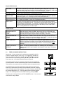
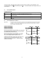
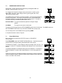
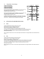
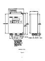
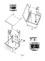
222 W. Memorial Road, Oklahoma City, OK 73114-2317 Phone: 1-800-624-7697 Fax: 405-755-8425 www.magpowr.com E-mail: [email protected] INSTRUCTION MANUAL VERSATECTM TENSION CONTROL MODELS: VTC & VTC-E TABLE OF CONTENTS Section 1 2 3 4 5 6 7 8 9 10 11 12 Title Page Introduction.................................2 Installation ..................................2 Electrical Connections................3 Tension Mode.............................3 Dancer Mode..............................6 Free Loop Mode .........................9 Ranger Mode............................12 Power Amp...............................13 Optional Connections ...............14 Common Features....................16 Trouble Shooting ......................17 Reset Procedures.....................18 No. Figures Page 1 2 3 4 5 6 7 8 9 Specifications ........................... 19 Wiring Isolated Inputs............... 20 Outline Dimensions VTC .......... 20 Outline Dimensions VTC-E ...... 21 Power Amp Instructions ........... 22 Wiring Diagrams....................... 23 Tension Mode Flow Chart ........ 24 Dancer Mode Flow Chart ......... 25 Free Loop Mode Flow Chart..... 26 Ranger Mode Flow Chart ......... 27 All of the information herein is the exclusive proprietary property of Maxcess International, and is disclosed with the understanding that it will be retained in confidence and will neither be duplicated nor copied in whole or in part nor be used for any purpose other than for which disclosed. Copyright 2004, all rights reserved. Periodically there will be updates to this manual. The latest version is available at www.magpowr.com or by calling 1-800-MAGPOWR (624-7697). 850A232-1 12/06 Rev. D 1. INTRODUCTION ® The MAGPOWR Model VERSATEC is a microprocessor-based control, designed for precise tension control of a moving web. The VERSATEC is capable of controlling web tension in unwind and rewind systems when in Tension mode, dancer position when in Dancer mode, loop position when in Free Loop mode, or the Versatec can be used as a ranging control when in Ranger mode. Throughout this manual, instructions or options specific to one of the operating modes (Tension, Dancer, Free Loop or Ranger mode) will be contained in the corresponding section. Instructions and options common to all modes will be grouped together. Throughout this manual, bold words or symbols represent keystrokes. All data entry and calibration is done through the touch pad keyboard. In some numerical data screens, pressing Í or Î moves a cursor below the digits. The underlined digit can be changed with the + or -. 2. INSTALLATION ENVIRONMENTAL The VERSATEC, Model VTC-E and its variants are intended for mounting on any flat vertical surface capable of supporting it. See Figures 2 and 3 for dimensions. The VTC-E meets the environmental and mechanical requirements of EN50178 with the exception that the degree of protection provided by the VTC-E enclosure is IP65 which is more stringent than the standard. If the IP65 rating is required in the final installation, sealing type cable grips should be used for cable entry. Four mounting holes are provided for attachment of the VTC-E to the mounting surface. The means of attachment should comply with the essential requirements of the appropriate standard(s) and is the responsibility of the installer. The VERSATEC, Model VTC is intended for installation through a DIN panel opening. The panel itself should exhibit sufficient strength to support the weight of the VTC as well as insure the integrity of the environmental seal. The VTC maintains a degree of protection of IP65 over its front panel. It also meets the environmental and mechanical requirements of EN50178. The VTC mounting clips found on both sides of the enclosure behind the front panel will accommodate panel thickness of 0.06 inches (1.5 mm) to 0.5 inches (12 mm). Wiring to and from the enclosure must be done with double or reinforced insulation or protective screening which provides protective separation. All wiring outside either of the Versatec enclosures should comply with the essential requirements of the appropriate standard(s) and is the responsibility of the installer. The US-2 ultrasonic sensor must be mounted 6 inches (152 mm) or greater from any target, and not more than 60 inches (1524 mm) from any target. If using a magnetic particle clutch or brake, see Section 8 to install Power Amplifiers. WARNING: DISCONNECT MAINS BEFORE OPENING ENCLOSURE MAINTENANCE The only maintenance that may be required on VTC is fuse replacement. Replacement of any fuse requires opening the enclosure, which circumvents the enclosure IP rating. To replace a fuse: On Model VTC and its variants: On Model VTC-E and its variants: 1. Disconnect the supply mains. 2. Remove the two screws on the rear of the VTC which retain the top cover. 3. Remove the top cover 4. Remove the PA-90 or PA-2 power amplifier if present 5. Remove and replace the blown fuse. 6. Re-install the PA-90 or PA-2 and the top cover. 7. Reconnect supply mains. 1. Disconnect the supply mains. 2. Open the door of the VTC-E by loosening the two retaining screws. 3. Remove the PA-90 or PA-2 power amplifier if present 4. Remove VTC-E and replace the blown fuse. 5. Re-install the PA-90 or PA-2. 6. Close the door and re-tighten the retaining screws. 7. Reconnect supply mains. 2 3. ELECTRICAL CONNECTIONS Figure 5 shows the connections that are required for the basic Versatec system. They are: 115 or 230 vac power MAGPOWR US-2 ultrasonic sensor RUN/STOP using the Versatec internal logic supply Control OUTPUT to clutch, brake, motor controller, etc Power Amplifier input (if used) 115 vac for 90 vdc clutch or brake, or 24 vdc for a 24 vdc clutch or brake. See Section 9 for other options and connections. Route AC power away from sensor and control wiring. MAGPOWR sensor cables are color coded on the nameplate. Run all wiring in shielded cable. Connect shields to the enclosure using the standoffs provided. Maximum shield length and maximum length of wires outside of the shield is 3 inches (75 mm). 4. TENSION MODE INSTRUCTIONS Apply power. Screen contrast can be adjusted by pressing Í and Î for 2 seconds. Adjust using the + and keys. The Versatec is shipped from the factory in Tension mode. The HOME screen (below) always appears at power up. HOME also returns you to this screen. Automatic mode: The output automatically adjusts to correct for changes in roll diameter Manual mode: Switch to Manual mode anytime using the AUTO/MANUAL key. The output is now fixed at the level set in the MANUAL LEVEL screen. Switch back to Automatic mode using the AUTO/MANUAL key. Stopping: During the Stop Time, the Versatec is still in Automatic mode, but the output is momentarily changed by Stop Multiplier. At the end of Stop Time, the Versatec switches to Hold mode. Hold Mode: In Tension mode, the Hold mode output is the same as the operating level. E-Stop: During Emergency Stop, the output goes to full on for unwind systems and to zero output for rewind systems. Off: The output is zero when tension is turned off either by the TENSION ON/OFF key or by a remote connection. Setup #: This number indicates the present setup. Alarm Indicators: The A1, or A2 will flash when the corresponding alarm is on. 3 The operator screens (shown in the figure) are those normally used during machine operation and are accessed using Ï or Ð from the HOME screen. A complete flow chart is shown in Figure 6. The OUTPUT LEVEL screen shows the present output when in Automatic mode. The MANUAL LEVEL screen shows the output when in Manual mode. The SETUP NUMBER screen shows the present setup number. The setup can be changed when in Hold mode by pressing Í or Î. The CORE TENSION and TAPER PERCENT screens only appear when using Taper Tension for rewinds. 4.1 Tension Mode Setup Basic setup cannot be performed if E-STOP is open, or if RUN/STOP is in run mode. To align the sensor, press PROGRAM and use ÍÎ to display SENSOR ALIGN. Press Ð. The screen will show the distance to the target when properly aligned and will show **** if no echo is received. Adjust the alignment of the US2 as necessary. Press PROGRAM and use Íor Î to enter the CONFIGURATION menu. Use Ð to access the SYSTEM screen. Use Íor Î to select unwind or rewind. Press PROGRAM, Ð to display the ROLL DIMENSIONS menu (shown in the figure). Enter the Full Roll Diameter, Core Diameter, and Distance to Axis. The Distance to Axis is the distance from the sensor to the centerline of the roll. Press HOME to return to the HOME screen. In the HOME screen press + or – to set the desired Tension Setpoint. Basic setup is complete. 4 4.2 Tension Mode Options Configuration Menu Screens TAPER TENSION TENSION ON/OFF CORE OFFSET Taper Tension can be used on rewinds to decrease the web tension as the diameter increases. To use taper, select yes for taper tension in the Configuration menu. Two new screens will appear in the operator loop. Enter the Core Tension setpoint and the Taper Percent. The taper percent is the percentage decrease in web tension from the core to full roll. When using Taper Tension, the Tension Setpoint % displayed on the HOME screen will show the tension setpoint at the present diameter. As the roll builds, the tension setpoint % will decrease as the diameter increases based on the amount of taper percent set. At full roll, it will show the core tension setpoint less the taper percent. Use this screen to select the method of using a remote connection to turn the tension on and off. Use this screen to adjust the output at core. Stop and Alarms Screens STOP TIME STOP MULTIPLIER MINIMUM DIAMETER DETECT (A1) MAXIMUM DIAMETER DETECT (A2) ALARM TIME DELAY ALARM HYSTERESIS DISTANCE This is the number of seconds from the time the user applies the stop signal until the system is stopped. The stop signal is applied by the user at terminals TB3.8 and TB3.6. After this time, the system output returns to the normal operating value. Stop Multiplier can be used on unwinds to provide extra torque to help stop the unwind roll. The control output is increased based on this multiplier and the present diameter during the stop time. The factory setting of 1.00 creates no increase in output. If tension falls during stop time, increase the value. Decrease the value if tension rises during stop. Enter the diameter of the desired minimum diameter detection point. The solid state relay output marked “ALARM1” at terminals TB4.1 and TB4.2 will close whenever diameter is less than or equal to the display value. NOTE: Hysteresis and delay will change the way the output works slightly. See below. Enter the diameter of the desired maximum diameter detection point. The solid state relay output “ALARM2” at terminals TB4.3 and TB4.4 will close whenever diameter is great than or equal to the display value. NOTE: Hysteresis and delay will change the way the output works slightly. See below Delays are timed from the moment the target reaches the trigger distance (minus hysteresis if any). If the target moves outside the trigger distance before the delay time is passed, the output will not activate and the delay will be reset as if the target had never reached the trigger distance. The factory setting is .010 seconds. Hysteresis allows the target to move a certain distance with no change in output status. It is used to prevent the output from chattering near the set detect distance. Hysteresis is set in distance units using the + and – keys. The factory setting is 0.1 UNWIND MINIMUM DIAMETER DETECT REWIND MAXIMUM DIAMETER DETECT 5 5.0 DANCER MODE INSTRUCTIONS For a Dancer system, you must also connect the MAGPOWR DFP or DFP-2 to pins TB3.10, TB3.11 and TB3.13 as shown in the wiring diagram Figure 5. The US-2 ultrasonic sensor is optional. Apply power. Screen contrast can be adjusted by pressing Í and Î for 2 seconds. Adjust using the + and keys. To configure the Versatec for Dancer mode (unit must be in “HOLD”), press Ï and Ð for 2 seconds. Then select Dancer mode by pressing Í or Î. Press Ð to enter the Dancer mode. The Dancer mode HOME screen (below) will now be displayed. You can always return to the HOME screen by pressing HOME. Automatic Mode: The output automatically adjusts to control dancer position. Stopping: During the Stop Time, the Versatec is in Automatic operation, but the output is momentarily changed by the Stop Multiplier and Inertia Compensation. After stop time expires, the unit is in Hold mode. Hold Mode: The output is held at the last running output level. Or, if Reset Hold is used, the output is set by the Reset Level. E-Stop: During an Emergency Stop condition, the output will go to maximum if using a torque device or minimum if controlling a speed device. Off: The output is zero when tension is turned off by the TENSION ON/OFF key or by a remote connection. Tension Off is only allowed in TORQUE mode. A complete flowchart is shown in Figure 7. The operator screens (shown in the figure) are those normally used during machine operation and are accessed by pressing Ï or Ð from the HOME screen. These are the only screens accessible when the setup is secured. The Setup Number screen can be used to change the Setup. You must be in Hold mode to change setup. If using the Tension Output, the TENSION screen will show the tension setpoint and the present output level. If using Taper Tension and Diameter Input, the last two screens will appear. 6 5.1 Dancer Mode Setup Setup cannot be performed if E-Stop is open, or if RUN/STOP is in run mode. 1. Choose control device. Press PROGRAM and Í or Î to access the Configuration menu. Press Ð until CONTROL DEVICE is displayed. Press Í or Î to select the type of device, Speed or Torque. If a brake or clutch is being used, choose torque. If a motor is being used, choose speed. 2. Configure the diameter signal. If not using a diameter signal, go directly to Step 3. From the Control Device screen, press Ð until DIAMETER SENSOR is displayed. Use Í or Î to choose YES. Press PROGRAM, and Í or Î to enter the Roll Dimensions menu. Press Ð. Enter the Full Roll Diameter, Core Diameter, and Distance to Axis. The Distance to Axis is the distance from the US-2 to the centerline of the roll. 3. Set the Dancer Position Press PROGRAM, Ð to enter the Dynamic Tuning menu. While holding the dancer arm in the desired running position. Press + and - until the display says OK. Press Ð. 4. Tuning The screen below is the Tuning screen. Pressing Í or Î when in this screen chooses CORE, FULL, or EXIT. Pressing Ï or Ð adjusts the dancer position (if necessary). Pressing + or – adjusts the tuning (+ will normally increase the stability and – will increase the responsiveness.) In the following steps, the words + (FULL) means to press + when FULL is selected, - (FULL) means to press – while FULL is selected, etc. When asked to “STABLIZE” an oscillation, perform one of the following steps: 1. If the dancer is oscillating rapidly (faster than several seconds per cycle), press + until the oscillation stops. OR 2. If the dancer is oscillating slowly (several seconds per cycle), press – until the oscillation stops. Torque device with a diameter signal or speed device (with or without diameter sensor): NOTE: The next step requires that the machine be running near full roll. If this is a rewind, a preliminary adjustment can be made at core with final tuning done at full roll. If the dancer position oscillates during winding, use the appropriate method above to stop the oscillation. With a full roll mounted run the machine at a low speed. If the dancer position is oscillating stabilize the dancer. If necessary, adjust the dancer position using Ï or Ð. If the dancer position is not oscillating, press – (FULL) until the dancer position begins to oscillate. NOTE: The next step requires that the machine be running near core. If this is an unwind you may mount a small roll, or you may continue to unwind until the roll approaches core. Select CORE. If the dancer position oscillates at any time during the unwind stabilize the dancer. Press Í or Î to select CORE. Run the machine at a low speed near core. If the dancer position is oscillating stabilize the dancer. If the dancer position is not oscillating, press – (CORE) until the dancer position begins to oscillate, and then press + (CORE) until oscillations stop. 7 Tuning is complete. Select EXIT and press Ð. This screen shows the condition of AUTO POSITION. It will normally be ON after tuning CORE and OFF after tuning FULL. It can be turned ON or OFF using this screen, but it is best left ON. If controlling a torque device with diameter signal, the AUTO POSITION is always ON, so the AUTO POSITION screen does not display in this mode. Press HOME. Torque device with no diameter signal: NOTE: The next step requires that the machine be running near core. If this is an unwind you may mount a small roll, or you may continue to unwind until the roll approaches core. Select CORE. If the dancer position oscillates at any time during the unwind press + (CORE) until the oscillations stop. With a small roll (near core) mounted run the machine at a low speed. If the dancer position is oscillating press + (CORE) until the oscillations stop. Adjust the dancer position using Ï or Ð if necessary. If the dancer does not oscillate, press - (CORE) until the dancer position begins to oscillate, and then press + (CORE) until the oscillations stop. NOTE: The next step requires that the machine be running near full roll. If this is a rewind, you may mount a full roll, or you may continue to wind until the roll approaches full. Select FULL. If the dancer position oscillates at any time during the wind, press + (FULL) until the oscillations stop. Press Í or Î to select FULL. Run the machine at a low speed near full roll. If the dancer position is oscillating press + (FULL) until the oscillations stop. If dancer position is not oscillating, press – (FULL) until the dancer position begins to oscillate, and then + (FULL) until oscillations stop. Tuning is complete. Select EXIT and press Ð. This screen shows the condition of AUTO POSITION. It will normally be ON after tuning FULL and OFF after tuning CORE. It can be turned ON or OFF using this screen, but it is best left ON. Press HOME. 5.2 Dancer Mode Options Configuration Screens TENSION ON/OFF DIAMETER SENSOR TENSION OUTPUT TAPER TENSION INTEGRATOR TIME PROPORTIONAL GAIN DERIVATIVE TIME FILTER TIME STOP TORQUE RATIO This is available when the control device is torque. Use this screen to select the method of using a remote connection to turn the tension on and off. The US-2 Ultrasonic sensor can be used to improve the stability of systems with large diameter ratios. The US-2 should be connected to TB2. A 4 to 20 madc signal is available at TB3.1 and TB3.4 to connect to the dancer loading device to set the tension in the web Taper tension can be used on rewind systems to decrease the web tension as the diameter increases if using the Tension Output and a diameter signal. The Tension Output to the dancer loading device at terminals TB3.1 and TB3.4 will decrease as the diameter increases. To use Taper Tension, select yes in the TAPER TENSION screen. Enter the core tension and the taper percent in the operator screens. The taper percent sets the percent decrease in tension from core to full roll. This time adjusts the response to errors. Larger values slow down the response to rapidly changing errors. The value is adjusted during Dynamic Tuning. Generates an output adjustment proportional to error. This value is adjusted during Dynamic Tuning. Gives an output adjustment proportional to the rate of change of error. The roll-off time constant. This value is preset at the factory. Adjustment is normally not needed. Ratio of torque required to stop a roll at core to the torque required to stop a full roll. This value is determined through Dynamic Tuning. 8 Stop and Hold Screens STOP TIME STOP MULTIPLIER INERTIA COMP HOLD LEVEL MULT RESET HOLD This is the time that the Versatec stays in Stopping (automatic) mode after the stop signal is received. After the Stop Time expires, the control goes to Hold mode. Stop Time should be slightly longer than the actual machine stopping time. The output in Hold mode is the last running output level, for torque control and 0 for speed control. Multiplies the output upon receipt of a stop signal. A value of 1.0 creates no increase. This is a simple adjustment for roll inertia during stopping. The percent increase in output required to stop the roll at the present diameter and running output level. The value will be computed automatically for changes in diameter. While running press + or – to change the value at the present diameter. The output in Hold Mode is the last running output level multiplied by this value. A value of 1.0 creates no increase. A value of 2.0 will double the output. The output in HOLD MODE is the last running output multiplied by the HOLD LEVEL MULTiplier. When changing from an empty roll to a full roll you may have insufficient output when you restart the machine. The symptom would be that the dancer arm would hit the low tension stop at startup. To avoid this, a momentary switch closure between terminals TB3.9 and TB3.6 will force the output into the value you enter under RESET HOLD. It is adjustable from 0 to 100% output. Alarms Screens MINIMUM DIAMETER DETECT ALARM 1 MAXIMUM DIAMETER DETECT ALARM2 ALARM TIME DELAY ALARM HYSTERESIS DISTANCE 6.0 Enter the diameter of the desired minimum diameter detection point. The solid state relay output marked “ALARM1” at terminals TB4.1 and TB4.2 will close whenever diameter is less than or equal to the display value. NOTE: Hysteresis and delay will change the way the output works slightly. See below. Enter the diameter of the desired maximum diameter detection point. The solid state relay output “ALARM2” at terminals TB4.3 and TB4.4 will close whenever diameter is great than or equal to the display value. NOTE: Hysteresis and delay will change the way the output works slightly. See below Delays are timed from the moment the target reaches the trigger distance (minus hysteresis if any). If the target moves outside the trigger distance before the delay time is passed, the output will not activate and the delay will be reset as if the target had never reached the trigger distance. The factory setting is .010 seconds. Hysteresis allows the target to move a certain distance with no change in output status. It is used to prevent the output from chattering near the set detect distance. Hysteresis is set in distance units using the + and – keys. The factory setting is 0.1 FREE LOOP MODE INSTRUCTIONS Apply power. Screen contrast can be adjusted by pressing Í and Î for 2 seconds. Adjust using the + and - keys. To configure the Versatec for Free Loop mode (unit must be in “HOLD”), press Ï and Ð for 2 seconds. Then select Free Loop mode by pressing Í or Î. Press Ð to enter the Free Loop mode. A complete flowchart is shown in Figure 8. The operator screens (shown in the figure) are those normally used during machine operation and are accessed using Ï or Ð from the HOME screen. These are the only screens which are accessible when the setup is secured. The HOME screen (top screen) displays the target setpoint and the actual distance, the present setup number, the system status (Automatic, Stopping, Hold, or E-Stop), and the alarm indicators. The alarm indicators will flash when the corresponding alarm is on. The output level screen shows the present output. You can always return to this HOME screen by pressing HOME. The setup can be changed from the SETUP NUMBER screen. You must be in Hold mode to change setups. 9 6.1 Free Loop Mode Setup Basic setup cannot be performed if E-STOP is open, or if RUN/STOP is in run mode. To begin, do the following: Press PROGRAM Press Ð to enter LOOP DISTANCES menu Continue through the flow chart at right entering desired data in each screen. The parameters DISTANCE FOR MAX OUTPUT and DISTANCE FOR MIN OUTPUT set the basic gain of the system. The free loop will operate between these distances. DISTANCE FOR MAX OUTPUT is not always greater than DISTANCE FOR MIN OUTPUT. The following rule defines which is greater: RULE: When the motor is at maximum RPM, the free loop will move from the DISTANCE FOR MAX OUTPUT toward the DISTANCE FOR MIN OUTPUT. Enter POSITION SETPOINT. If Auto Position is not being used the free loop will not stay exactly at this position. Adjustment may be needed later. 6.2 Free Loop Mode Tuning The screen below is the Tuning screen. Pressing Í or Î when in this screen chooses Full, Core, or Exit. Pressing Ï or Ð adjusts the loop position (if necessary). Pressing + or – adjusts the tuning (+ will increase the stability and – will increase the responsiveness.) In the following steps, the words + (Full) means to press + when Full is selected, - (Full) means to press – while Full is selected, etc. NOTE: The next step requires that a full roll be mounted. If this is a rewind, a preliminary adjustment can be made at core with final tuning done at full roll. If the loop position oscillates during winding, press + (FULL) until the oscillations stop. With a full roll mounted run the machine at a low speed. If the loop position is oscillating press + (FULL) until the oscillations stop. If necessary, adjust the loop position using Ï or Ð. If the loop position is not oscillating, press - (FULL) until the loop position begins to oscillate, and then press + (FULL) until the oscillations stop. NOTE: The next step requires that the machine to be running near core. If this is an unwind you may mount a small roll, or you may continue to unwind until the roll approaches core. Select CORE. If the loop position oscillates at any time during the unwind press + (CORE) until the oscillations stop. Press Í or Î to select CORE. Run the machine at a low speed near core. If the loop position is oscillating, press + (CORE) until the oscillations stop. If the loop position is not oscillating, press – (CORE) until the loop position begins to oscillate, and then press + (CORE) until oscillations stop. 10 Tuning is complete. Select EXIT and press Ð. This screen shows the condition of AUTO POSITION. It will normally be ON after tuning CORE and OFF after tuning FULL. It can be turned ON or OFF using this screen, but it is best left ON. 6.3 Free Loop Mode Options Configuration Screens INTEGRATOR TIME PROPORTIONAL GAIN DERIVATIVE TIME FILTER TIME 6.4 This time adjusts the response to errors. Larger values slow down the response to rapidly changing errors. The value is adjusted during Dynamic Tuning. Generates an output adjustment proportional to error. This value is adjusted during Dynamic Tuning. Gives an output adjustment proportional to the rate of change of error. The roll-off time constant. This value is preset at the factory. Adjustment is normally not needed. Free Loop Mode Stop and Alarms Stop Time This is the number of seconds from the time the user applies the stop signal until the system is stopped. The stop signal is applied by the user at terminals TB3.8 and TB3.6. After this time, the system output goes to zero. ALARM 1 ON DISTANCE ALARM 1 OFF DISTANCE ALARM 2 ON DISTANCE ALARM 2 OFF DISTANCE Enter the desired distance at which ALARM 1 or 2 is to turn ON. the solid state relay output ALARM 1 or 2, will close whenever the displayed distance equals this value. Enter the desired distance at which ALARM 1 or 2 is to turn OFF. The solid state relay output ALARM 1 or 2 will open whenever the displayed distance equals this value. ALARM OFF DISTANCE is usually set to a value which is far enough away from the ALARM ON DISTANCE so that chattering of the alarm will not occur. If delay is set, alarm actuation will be delayed. 11 7.0 RANGER MODE INSTRUCTIONS Apply power. Screen contrast can be adjusted by pressing Í and Î for 2 seconds. Adjust using the + and - keys. To configure the Versatec for Ranger mode (unit must be in “HOLD”), press Ï and Ð for 2 seconds. Select Ranger mode by pressing Í or Î. Press Ð to enter the Ranger mode. The HOME screen (top screen in the figure) appears. It shows the target distance and the present output. The number in the top left corner is the present setup. The alarm indicators (A1 andA2) will flash when the alarms are on. The letter in the bottom left corner indicates the status (either A or H). Automatic Mode: The output automatically adjusts to changes in target position. Hold Mode: The output is zero when in Hold mode. The setup can be changed from the SETUP NUMBER screen when in Hold mode. The HOME screen and SETUP NUMBER screen are the only screens accessible when security is set. You can always return to the HOME screen by pressing HOME. A complete flowchart is shown in Figure 9. 7.1 Ranger Mode Setup Basic setup cannot be performed if E-STOP is open, or if RUN/STOP is in run mode. Press PROGRAM to enter the TARGET DISTANCES menu. Continue through the screens shown in the figure entering the desired data in each screen. The Distance for Display = 0 is the distance at which a reading of 0.0 is to occur. For example, if a value of 7 is entered, the Distance will display 0.0 at 7 inches from the sensor. The Readout Multiplier is the desired scaling value of the Distance. For example, a Readout Multiplier of 3 would make a target distance of 12.0 inches appear as a 36.0. Distance for Display=0, and Readout Multiplier automatically convert the displayed values for Distance, Position, Distance for Max Output, Distance for Min Output and Alarm 1 and Alarm 2 On and Off. 12 7.2 Ranger Option – Alarm Settings ALARM 1 ON DISTANCE ALARM 1 OFF DISTANCE ALARM 2 ON DISTANCE ALARM 2 OFF DISTANCE Enter the desired distance at which ALARM 1 or 2 is to turn ON. The solid state relay output ALARM 1 or 2, will close whenever the displayed distance equals this value. Enter the desired distance at which ALARM 1 or 2 is to turn OFF. The solid state relay output ALARM 1 or 2 will open whenever the displayed distance equals this value. ALARM OFF DISTANCE is usually set to a value which is far enough away from the ALARM ON DISTANCE so that chattering of the alarm will not occur. If delay is set, alarm actuation will be delayed. 8.0 INSTALLATION OF POWER AMPLIFIERS (IF USED) 8.1 PA-90 Install the PA-90 before applying power to the control. Remove the VTC cover, or open the VTC-E door. Set JP1 on the Versatec p.c. board to “0-10V”. Set JP1 on the power amplifier for the desired output current range. On model VTC, unplug TB6 and remove the knockout from the rear of the enclosure. Mount Power Amplifier per Figure 4 using the standoffs provided with the PA-90. Re-secure cover or door. When using the PA-90, the 0 to 10 vdc control output is still active but no longer isolated, and is referenced to the AC line. 8.2 PA-2 Install the PA-2 before applying power to the control. Remove the VTC cover, or open the VTC-E door. Set JP1 on the Versatec p.c. board to “0-10V”. Set JP1 and JP2 on the power amplifier for the desired output voltage and current range. On model VTC unplug TB6 and remove the knock-out from the rear of the enclosure. Mount Power Amplifier per Figure 4 using the standoffs provided with the PA-2. Re-secure cover or door. When using the PA-2, the 0 to 10 vdc control output is still active but no longer isolated, and is referenced to the AC line. 13 9. OPTIONAL CONNECTIONS, FUNCTIONS AND OTHER TECHNICAL INFORMATION A complete wiring diagram is shown in Figure 5. TABLE OF CONTENTS FUNCTION RUN/STOP........................................................................................................ 9.1 E-STOP ............................................................................................................. 9.2 REMOTE TENSION ON/OFF........................................................................... 9.3 DANCER POSITION SENSOR ........................................................................ 9.4 ALARM .............................................................................................................. 9.5 TENSION ON/OFF OUTPUT ........................................................................... 9.6 OUTPUT INDICATORS.................................................................................... 9.7 TENSION OUT.................................................................................................. 9.8 INVERSE DIAMETER OUTPUT ...................................................................... 9.9 TENSION UP / TENSION DOWN .................................................................... 9.10 REMOTE SETUP SELECT .............................................................................. 9.11 ISOLATED LOGIC INPUTS.............................................................................. 9.12 SELECTING OUTPUT VOLTAGE/CURRENT.............................................. 9.13 RESET HOLD.................................................................................................. 9.14 9.1 RUN/STOP Connect TB3.6 to TB3.8 to initiate the stopping function. Open the connection between TB3.6 and TB3.8 to run. When using the internal 5 vdc supply (set JP6-5 (OPTO SUPPLY) to INT (internal)), 2 madc flows in the switch. See Section 9.12 to use isolated logic inputs (5 or 24 vdc). 9.2 E-STOP (E-STOP IS AN AUXILIARY FUNCTION NOT INTENDED TO PROVIDE SAFETY PROTECTION) CATEGORY 1 Open the connection between TB3.6 and TB3.7 to initiate E-STOP. To run again, connect TB3.6 and TB3.7 and toggle the run/stop connection. When using the internal 5 vdc supply (set JP6-5 (OPTO SUPPLY) to INT (internal)), 2 madc flows in the switch. See Section 9.12 to use isolated logic inputs (5 or 24 vdc). 9.3 REMOTE TENSION ON/OFF The output can be set to zero from a remote location by using the remote Tension On/Off. Either of two optional modes of operation are selected using PROGRAM-CONFIGURATION. TOGGLE duplicates TENSION ON/OFF on the keypad. A momentary connection between TB3.5 and TB3.6 will toggle between TENSION ON and OFF. When the toggle is selected, the TENSION ON/OFF key remains functional. LEVEL turns TENSION OFF when TB3.6 is connected to TB3.5. When level is selected, the TENSION ON/OFF key is disabled. When using the internal 5 vdc supply (set JP6-5 (OPTO SUPPLY) to INT (internal)), 2 madc flows in the switch. See Section 9.12 to use isolated logic inputs (5 or 24 vdc). 9.4 DANCER POSITION SENSOR Connect DFP or DFP2 to terminals TB3.10, TB3.11, TB3.13 (TB3.12 is not used) when using Dancer mode. 14 9.5 ALARM 1, ALARM 2 Both alarm outputs function identically but are independent. Each has an open collector, open emitter NPN output which can switch up to 100 ma at 30 vdc. The alarm output can be made TTL compatible by setting JP3 and JP4 to the 4 ma setting. An output is considered to be on when the VTC connects the two terminals together. For example, when ALARM 1 is turned on, terminals TB4.1 and TB4.2 are connected together. When in Tension mode or Dancer mode with a diameter signal, ALARM 1 turns on when the target reaches the MIN DIAMETER DETECT distance. ALARM 2 turns on when the target reaches the MAX DIAMETER DETECT distance. When in Ranger mode or Free Loop mode there are four distance settings ALARM 1 ON DISTANCE, ALARM 1 OFF DISTANCE, ALARM 2 ON DISTANCE, and ALARM 2 OFF DISTANCE which determine at what target position each alarm will turn on or off. JP2 can be used to make this output TTL compatible. 9.6 TENSION ON/OFF output This is an output which has the same electrical capabilities as the ALARM outputs. The Versatec connects terminals TB4.5 and TB4.6 when tension is on and disconnects them when tension is off. 9.7 TENSION INDICATORS (0 to1 madc) A 1 madc meter may be connected to terminals TB3.2 and TB3.4 to get a remote indication of % TENSION setpoint. 9.8 TENSION OUT (4 to 20 madc) A 4 to 20 madc signal is provided to set the load on the dancer arm. Connect to terminals TB3.1 and TB3.4. 9.9 INVERSE DIAMETER OUTPUT (0 to 10 vdc) A 0 to10 vdc output is provided that is inversely proportional to diameter. This can be used on rewinds that utilize clutches to reduce the motor input speed as the roll builds, which will reduce the heat dissipation in the rewind clutch. Connect to terminals TB3.3 and TB3.4. You must have a US-2 diameter signal to use this feature. 9.10 TENSION UP / TENSION DOWN TENSION MODE: Connecting terminal TB3.17 to TB3.15 will cause tension (when in Auto mode) or the manual level (when in Manual mode) to increase. Connecting terminal TB3.18 to TB3.15 will cause tension (when in Auto mode) or the manual level (when in Manual mode) to decrease. FREE LOOP MODE: Connecting terminals TB3.17 and TB3.15 will increase position. TB3.18 and TB3.15 will decrease position. DANCER MODE: Connecting terminals TB3.17 and TB3.15 will increase the Tension output. TB3.18 and TB3.15 will decrease the Tension output. 9.11 REMOTE SETUP SELECT The setup can be changed remotely. The Versatec must be in Hold mode to change setup. The following table defines the function of the setup select terminals. Setup 1 2 3 4 TB3.16 Open Open Closed Closed 15 TB3.14 Open Closed Open Closed 9.12 ISOLATED LOGIC INPUTS If it is desired to isolate the logic inputs on TB4 to interface with other equipment or for increased noise immunity, an external power supply can be used as shown in Figure 1. On the main PCB set JP6 and JP5 (OPTO SUPPLY) to EXT (external). 9.13 SELECTING OUTPUT VOLTAGE/CURRENT The output voltage/current at TB5.1(+)and TB5.2(-) is set by positioning jumpers on JP1 as shown in figure to the right. JP1 must be set for 0 to 10 vdc when the PA-90 or PA-2 Power Amplifiers are used. The –10 to +10 vdc output is normally used with regenerative drives in torque mode. When using –10 to +10 vdc output, select –10 to +10 vdc in the OUTPUT RANGE screen of the Configuration menu. 9.14 RESET HOLD Connect TB3.9 to TB3.6 to enable reset hold. Used in Dancer mode only. 10. FEATURES COMMON TO ALL MODES The following are the screens which are common to all the operating modes. CONFIGURATION...........................................................................................10.1 STOP AND ALARMS.......................................................................................10.2 COPY SET-UPS ..............................................................................................10.3 UNLOCKED .....................................................................................................10.4 SENSOR ALIGN ..............................................................................................10.5 RECALIBRATE OUTPUT................................................................................10.6 10.1 CONFIGURATION SCREENS SELECT LANGUAGE ENGLISH, FRANCAIS, DEUTSCH, ESPANOL, or ITALIANO SELECT UNITS ENGLISH, METRIC OUTPUT RANGE Select –10 to +10 vdc if using a regenerative drive. ECHO REJECT DIST The VERSATEC ignores objects that are closer to the ultrasonic sensor than this distance. The minimum distance allowed between the actual target and ECHO REJECT DISTANCE is 2 inches (50 mm). 10.2 STOP AND ALARMS SCREENS ALARM TIME DELAY Delays are timed from the moment the target reaches the trigger distance (minus hysteresis if any). If the target moves outside the trigger distance before the delay time is passed, the output will not activate and the delay will be reset as if the target had never reached the trigger distance. The factory setting is .010 seconds. 16 10.3 COPY SETUPS There are four independent setups. Each contains its own complete set of parameters. You can switch between setups only while stopped using the setup number screen, in the OPERATOR LOOP. Each setup can be entered individually as described in the previous sections, or the parameters in any one setup can be copied to any other setup by using the COPY SETUPS screen. COPY SETUPS always copies from a selected setup to the present setup. You can also copy the factory DEFAULTS to the present setup. 10.4 UNLOCKED PROGRAM-UNLOCKED can be used to prevent changes to all the programming parameters. When secured, only values in the operator screens can be changed. 10.5 SENSOR ALIGN The sensor align screen is provided to aid in initial positioning of the US-2 sensor. The screen will show **** if no echo is received and will show the distance to the target when properly aligned. 10.6 RECALIBRATE OUTPUT The RECALIBRATE OUTPUT screen allows fine adjustment of the output voltage/current at 0% and 100%. Use the + or – keys to adjust the actual output with a meter on TB5.1 and TB5.2 11. TROUBLE SHOOTING FOR ALL OPERATING MODES PROBLEM Screen blank or hard to read POSSIBLE CAUSE Contrast misadjusted Power select switch improperly set. Output always low TENSION ON/OFF set to OFF SOLUTION OR DIAGNOSTIC Press Í, Î for 2 seconds. Use + and - to adjust. Set 115/230 vac power select switch to the appropriate voltage. If REMOTE TENSION ON/OFF is set to “TOGGLE” press TENSION ON/OFF on the keypad once. If REMOTE TENSION ON/OFF is set to “LEVEL” one or more of the remote tension off switches are closed. E-STOP is active (except unwind). E-STOP is wired incorrectly. JP6-5 not set for the proper logic supply. Output always high E-STOP is active (unwinds only). If the internal logic is being used (the factory default) TB3.6 must be connected to TB3.7 to disable E-STOP. Also verify JP6-5 is set to “INT”. If an external logic supply is used see Section 9.12. E-STOP is wired incorrectly. If the internal logic is being used (the factory default) TB3.6 must be connected to TB3.7 to disable E-STOP. Also verify JP6-5 is set to “INT”. JP6-5 not set for the proper logic supply. If an external logic supply is used see Section 9.12. 17 Cannot enter PROGRAM Not in Hold mode: RUN/STOP not wired correctly. JP6-5 not set for the proper logic supply. Front panel TENSION ON/OFF does not work If the internal logic supply is being used (the factory default) TB3.8 must be connected to TB3.6 to be in Hold mode. Also verify JP6-5 set to “INT”. If an external logic supply is used see Section 9.12. VTC configured for LEVEL for external TENSION ON/OFF When LEVEL is selected for TENSION ON/OFF only external tension on/off can be used. E-STOP is active If the internal logic is being used (the factory default) TB3.6 must be connected to TB3.7 to disable E-STOP. Also verify JP6-5 set to “INT”. E-STOP is wired incorrectly JP6-5 not set for the proper logic supply. If an external logic supply is used see Section 9.12. This is normal for Free Loop and Dancer, Speed modes. Cannot change to a different setup Not in Hold mode RUN/STOP not wired correctly JP6-5 not set for the proper logic supply Remote setup selection enabled 12. If the internal logic supply is being used (the factory default) TB3.8 must be connected to TB3.6 to be in Hold mode. Also verify JP6-5 set to “INT”. If an external logic supply is used see Section 9.12. You cannot change setup from the keypad when using remote setup selection. RESET PROCEDURES If it is desired to reset parameters to factory default values perform one of the following reset procedures: 1. 2. 3. 4. 5. 6. 7. Turn the power to the Versatec “OFF” for 5 seconds. Press + and - simultaneously. While holding the keys down, turn the power “ON”. Release both keys when the screen appears. The screen will display “RESET Í NO Δ Press Î to display “RESET ÍYES Δ Press Ð. Program reset is complete. The basic setup has been erased, and all other programming has been reset to factory default values The VERSATEC has returned to the Tension Mode 18 VERSATEC Specifications Supply Voltage Supply Frequency: Fuses: F1, F2 Enclosure VTC VTC-E Front Panel Enclosure Climatic Class: Temperature Range: Operating Storage Relative Humidity Pollution Degree: Altitude: Compatible Residual Current Devise Types: Worst Case Fault Current: Inputs: 115 or 230 vac, ±10% 50 or 60 cycles per second, sinusoidal 1.6 amp, Littelfuse Part No. 21601.6, or Wickmann Part No. 19194-053-FS IP65 (IEC529) IP20 (IEC529) IP65 (IEC529) 3K3 (EN60721) 0°C to 40°C -30°C to +80°C 5% to 85% 2 (IEC664-1) 0 to 2000 m A or B (IEC755) 1.6 amp ac Power Ultrasonic Sensor E-Stop Run/Stop Tension On/Off Remote Setup Select Remote Tension Adjust Reset Hold Dancer Position Outputs: 115/230 vac +/- 10%, 50/60 Hz Switch selectable, 1.6 amp max MAGPOWR US-2 Switch closure or 5 vdc or 24 vdc logic Switch closure or 5 vdc or 24 vdc logic Switch closure or 5 vdc or 24 vdc logic Switch closure, or 5 vdc or 24 vdc logic Switch closure, or 5 vdc or 24 vdc logic Switch closure, or 5 vdc or 24 vdc logic MAGPOWR DFP or DFP-2 Sensor (0 to 5 vdc) 1 to 10 kohm potentiometer Control Output 0 to 10 vdc, 1 ma max 4 to 20 madc, 500 ohm max -10 to +10 vdc, 1 madc max Inverse Diameter 0 to 10 vdc, 1 madc max Tension Output 4 to 20 madc, 500 ohm max Tension Output Reference 0 to 1 madc, 500 ohm max Alarm Outputs 1 & 2 dc solid state relay; 100 madc, 30 vdc max or TTL levels Tension On/Off Reference dc solid state relay; 100 madc, 30 vdc max or TTL levels US-2 Sensing Range: 6 in. (152 mm) to 60 in. (1524 mm) Resolution: .025% of span, or .007 in. (.18 mm) whichever is larger Typical Accuracy: .05 in. at 25ºC Error due to air temperature change: .2% / ºC Figure 1 MODEL VTC Figure 2 20 MODEL VTCE Figure 3 21 Figure 4 22 Figure 5 23 Figure 6 Figure 7 Figure 8 Figure 9