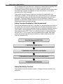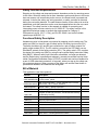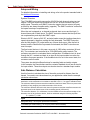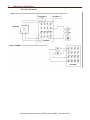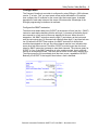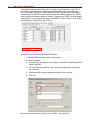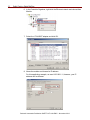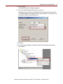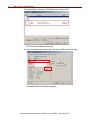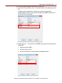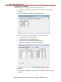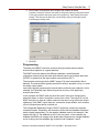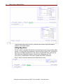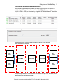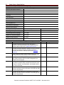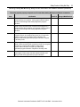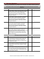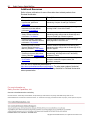
1
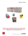
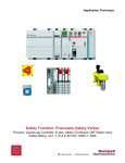
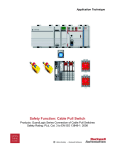
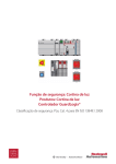
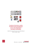
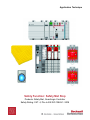
Application Technique
Safety Function: Safety Mat Stop
Products: Safety Mat, GuardLogix Controller
Safety Rating: CAT. 4, PLe to EN ISO 13849-1: 2008
2
Safety Function: Safety Mat Stop
Important User Information
Read this document and the documents listed in the additional resources section about installation,
configuration, and operation of this equipment before you install, configure, operate, or maintain this
product. Users are required to familiarize themselves with installation and wiring instructions in addition
to requirements of all applicable codes, laws, and standards.
Activities including installation, adjustments, putting into service, use, assembly, disassembly, and
maintenance are required to be carried out by suitably trained personnel in accordance with applicable
code of practice.
If this equipment is used in a manner not specified by the manufacturer, the protection provided by the
equipment may be impaired.
In no event will Rockwell Automation, Inc. be responsible or liable for indirect or consequential
damages resulting from the use or application of this equipment.
The examples and diagrams in this manual are included solely for illustrative purposes. Because of the
many variables and requirements associated with any particular installation, Rockwell Automation, Inc.
cannot assume responsibility or liability for actual use based on the examples and diagrams.
No patent liability is assumed by Rockwell Automation, Inc. with respect to use of information, circuits,
equipment, or software described in this manual.
Reproduction of the contents of this manual, in whole or in part, without written permission of Rockwell
Automation, Inc., is prohibited.
Throughout this manual, when necessary, we use notes to make you aware of safety considerations.
WARNING: Identifies information about practices or circumstances that can
cause an explosion in a hazardous environment, which may lead to personal
injury or death, property damage, or economic loss.
ATTENTION: Identifies information about practices or circumstances that can
lead to personal injury or death, property damage, or economic loss. Attentions
help you identify a hazard, avoid a hazard, and recognize the consequence.
IMPORTANT
Identifies information that is critical for successful application and
understanding of the product.
Labels may also be on or inside the equipment to provide specific precautions.
SHOCK HAZARD: Labels may be on or inside the equipment, for example, a
drive or motor, to alert people that dangerous voltage may be present.
BURN HAZARD: Labels may be on or inside the equipment, for example, a
drive or motor, to alert people that surfaces may reach dangerous
temperatures.
ARC FLASH HAZARD: Labels may be on or inside the equipment, for
example, a motor control center, to alert people to potential Arc Flash. Arc
Flash will cause severe injury or death. Wear proper Personal Protective
Equipment (PPE). Follow ALL Regulatory requirements for safe work practices
and for Personal Protective Equipment (PPE).
Rockwell Automation Publication SAFETY-AT118A-EN-P – November 2013
Safety Function: Safety Mat Stop
3
General Safety Information
Contact Rockwell Automation to find out more about our safety risk assessment
services.
IMPORTANT
This application example is for advanced users and
assumes that you are trained and experienced in safety
system requirements.
ATTENTION: Perform a risk assessment to make sure all
task and hazard combinations have been identified and
addressed. The risk assessment can require additional
circuitry to reduce the risk to a tolerable level. Safety circuits
must take into consideration safety distance calculations,
which are not part of the scope of this document.
Table of Contents
General Safety Information ....................................................................................... 3
Introduction ............................................................................................................... 3
Safety Function Realization: Risk Assessment ......................................................... 4
Safety Mat Safety Function ....................................................................................... 4
Safety Function Requirements .................................................................................. 5
Functional Safety Description ................................................................................... 5
Bill of Material ........................................................................................................... 5
Setup and Wiring ...................................................................................................... 6
Safe Distance Calculation ......................................................................................... 6
Configuration ............................................................................................................ 9
Programming .......................................................................................................... 17
Falling Edge Reset.................................................................................................. 18
Calculation of the Performance Level...................................................................... 19
Verification and Validation Plan............................................................................... 21
Additional Resources .............................................................................................. 26
Introduction
This safety function application technique explains how to wire, configure, and
program a Compact GuardLogix® controller and POINT Guard I/O™ module to
monitor a 440F safety mat.
This application technique assumes a dual-channel safety mat. It also assumes that
the dual-channels are shorted together whenever the safety mat is stepped on.
When this type of safety mat is wired directly into a safety input module, there is no
way to distinguish between an actual wiring short between the two channels and
stepping onto the mat. When either occurs, a short is created between the channels.
For this reason, a machine stop must be the default state when the mat is stepped
Rockwell Automation Publication SAFETY-AT118A-EN-P – November 2013
4
Safety Function: Safety Mat Stop
on. The machine can never start due to a channel-to-channel field wiring short. This
would be possible if stepping onto the mat caused the machine to start.
If a demand is placed on the safety mat or a fault is detected in the monitoring circuit,
the GuardLogix controller de-energizes the final control devices, in this case, a
redundant pair of 100S contactors.
This example uses a Compact GuardLogix controller, but is applicable to any
GuardLogix controller. This example also uses a 440F safety mat, but is applicable
to any dual-channel safety mat that shorts the channels together when the mat is
stepped on. The Safety Integrity Software Tool for the Evaluation of Machine
Applications (SISTEMA) software calculations shown later in this document must be
recalculated if different products are used.
Safety Function Realization: Risk Assessment
The required performance level (PLr) is the result of a risk assessment and refers to
the amount of the risk reduction to be carried out by the safety-related parts of the
control system. Part of the risk reduction process is to determine the safety functions
of the machine. In this application, the PLr by the risk assessment is Category 3,
Performance Level d (CAT. 3, PLd), for each safety function. A safety system that
achieves CAT. 3, PLd, or higher, can be considered control reliable. Each safety
product has its own rating and can be combined to create a safety function that
meets or exceeds the PLr.
From: Risk Assessment (ISO 12100)
1. Identification of safety functions
2. Specification of characteristics of each function
3. Determination of required PL (PLr) for each safety function
To: Realization and PL Evaluation
Safety Mat Safety Function
This application includes one safety function: a Category 0 stop by actuation of a
safety mat.
Rockwell Automation Publication SAFETY-AT118A-EN-P – November 2013
Safety Function: Safety Mat Stop
5
Safety Function Requirements
Stepping on the safety mat stops and prevents hazardous motion by removing power
to the motor. When the safety mat is reset, hazardous motion and power to the motor
does not resume until a secondary action occurs—the Reset button is pressed and
released. A fault at the safety mat, wiring terminals, or safety controller is detected
before the next safety demand. The safe distance location of the safety mat must be
established such that hazardous motion must be stopped before the user can reach
the hazard. The safety function in this example is capable of connecting and
interrupting power to motors rated up to 9 A, 600V AC. The safety function in this
application technique meets or exceeds the requirements for Category 3,
Performance Level d (CAT. 3, PLd), per EN ISO 13849-1 and control reliable
operation per ANSI B11.19.
Functional Safety Description
Hazardous motion is interrupted or prevented by stepping onto the safety mat. The
safety mat (SM1) is wired to a pair of safety inputs of a safety input module (SI1).
The safety contactors (K1 and K2) are connected to a pair of safety outputs of a
safety output module (SO1). The I/O module is connected via CIP Safety over an
EtherNet/IP network to the safety controller (SC1). The safety code in SC1 monitors
the status of the safety mat (SM1) by using the pre-certified safety instruction Safety
Mat (SMAT). When all safety input interlocks are satisfied, no faults are detected,
and the Reset button is pressed and released, a second pre-certified function block
called Configurable Redundant Output (CROUT) controls and monitors feedback for
a pair of 100S redundant contactors. In summary, when you step on the safety mat,
the contactors drop out. When you step off the safety mat and the Reset button is
pressed and released, the contactors are energized.
Bill of Material
This application uses these products.
Cat. No.
Description
Quantity
Mat guard safety mat, 1000 x 1000 mm (3.3 x 3.3 ft), 4.5 m
440F-M2020BYNN (14.8 ft) cables, yellow
1
800F reset push button - metal, guarded, blue, R, metal
800FM-G611MX10 latch mount, 1 N.O. contact, standard
1
100S-C09ZJ23C
Bulletin 100S-C - Safety Contactors
2
1768-ENBT
CompactLogix™ EtherNet/IP bridge module
1
1768-L43S
Compact GuardLogix processor, 2.0 Mb standard memory,
0.5 Mb safety memory
1
1768-PA3
Power supply, 120/240V AC Input, 3.5 A @ 24V DC
1
1769-ECR
Right end cap/terminator
1
1734-AENT
24V DC Ethernet adapter
1
1734-TB
Module base with removable IEC screw terminals
4
1734-IB8S
POINT Guard I/O safety input module
1
1734-OB8S
POINT Guard I/O safety output module
1
1783-US05T
Stratix 2000™ unmanaged Ethernet switch
1
Rockwell Automation Publication SAFETY-AT118A-EN-P – November 2013
6
Safety Function: Safety Mat Stop
Setup and Wiring
For detailed information on installing and wiring, refer to the product manuals listed in
the Additional Resources.
System Overview
The 1734-IB8S input module sources the 24V DC for both channels using two test
outputs. The input module synchronizes the 24V DC for both channels using two
safety inputs. The safety mat (SMAT) instruction toggles the test outputs (sources)
so that they are always complementary (opposite). The SMAT instruction verifies that
the inputs are always complementary.
When the mat is stepped on, a channel-to-channel short occurs and the high (1)
channel has a path to both inputs. The SMAT instruction detects that the inputs are
not complementary and drops the SMAT output.
Shorts to 0V DC, shorts to 24V DC, and wire breaks cause the toggling channels to
operate improperly; therefore, making the fault detectable. The SMAT instruction
sets the fault present (FP) output when any of these faults occur. After the fault is
cleared, and the Reset button is pressed and released, the SMAT instruction can
reset its output.
The final control devices, in this case, are a pair of 100S safety contactors (K1 and
K2). The contactors are controlled by a 1734-OB8S safety output module. The
contactors are wired in a redundant series configuration. A feedback circuit is wired
through the N.C. contacts and back to an input on the input module to monitor the
contactors for proper operation. If the feedback circuit is not in the correct state, the
contactors cannot restart.
The system has individual Reset buttons for resetting faults and safety outputs.
In this example, the Reset buttons and the contactor feedback circuit are all wired to
the input module. These three inputs can also be wired to a standard input module.
Safe Distance Calculation
Use this formula to calculate the size of the safety mat and its distance from the
hazard. You need to use values based on your application rather than the example
calculation shown here.
The select and use of pressure-sensitive mats/floors is dependent on the appropriate type-C
standard or a risk assessment in accordance with ISO 14121-1, if no type-C standard exists.
The minimum width of pressure-sensitive mats/floors shall be at least 750 mm to prevent the
possibility of easy stepping over without actuation of the device.
The minimum distances derived in this clause for pressure-sensitive mats/floors assume the
approach speed to the hazard zone will be at walking speed (1600 mm/s).
The minimum distance, S, in millimeters, from the hazard zone to the outermost edge of the
detection zone of the protective device, shall be calculated using the following equation.
S = (1600 x T) + 1200
Input
Safety Mat delay = 25 ms (from product documentation)
1734-IB8S input module delay = 16 ms (from product documentation)
1
Input module connection delay
Rockwell Automation Publication SAFETY-AT118A-EN-P – November 2013
Safety Function: Safety Mat Stop
7
2
Safety controller delay
•
Safety Task Watchdog
•
Safety Task Period
3
Output module connection delay
1734-OB8S output module delay = 6 ms (from product documentation)
Contactor response time = 15 ms (from product documentation)
Actual machine stop time = assume 900 ms for this example
1
The input module connection delay defaults to 4 x requested packet interval (RPI).
If we assume a RPI of 10 ms, the maximum delay = 40 ms
The worst case reaction time can be calculated by assuming there is only a single fault in the
control system. This means that only the higher of the two connection delay values shown
above needs to be included in the time (T) calculation. For this example, 40 ms is used, and
the 30 ms is excluded. To account for multiple faults occurring at the same time, use both
values in the calculation.
2
The safety controller delay is a combination of the safety task period plus the safety task
watchdog. The watchdog accounts for the possibility that the safety code runs right up to,
but does not trip the watchdog. The safety task period accounts for the possibility that the
asynchronous scan just ended when the input changed state. For this example, the
following assumptions were made:
Safety Task Period = 10 ms
Safety Task Watchdog = 5 ms
To calculate T, add the following:
• Safety Mat delay = 25 ms
• 1734-IB8S module delay = 16 ms
• Higher of input/output module connection delay = 40 ms
• Safety controller delay = 10 + 5 = 15 ms
• 1734-OB8S delay = 6 ms
• Contactor response time = 15 ms
• Measured actual machine stop time = 900 ms
Therefore, the T in this example is 1017 ms.
S = (K * T) + C – 0.4H = (63 * 1.017) + 47.2 - 0 = 111.27 in.
Conclusion: The safety mat’s far edge must be placed 111.27 in. away from the hazard.
3
The Output Module connection delay defaults to 3 x RPI.
If we assume an RPI of 10 ms, the maximum delay = 30 ms.
Rockwell Automation Publication SAFETY-AT118A-EN-P – November 2013
8
Safety Function: Safety Mat Stop
Electrical Schematic
24V DC
Safety Reset
Fault Reset
Safety Mat
1734-IB8S
24V DC COMMON
1734-OB8S
Rockwell Automation Publication SAFETY-AT118A-EN-P – November 2013
Safety Function: Safety Mat Stop
9
Configuration
The Compact GuardLogix controller is configured by using RSLogix™ 5000 software,
version 17 or later. First, you must create a new project and add the I/O modules,
then configure the I/O modules for the correct input and output types. A detailed
description of each step is beyond the scope of this document. Knowledge of the
RSLogix programming environment is assumed.
Configure the SMAT Instruction
The short-circuit detect delay time (SCDDT) is the amount of time (ms) the ` (SMAT)
instruction waits before declaring that the two high (1) channels at the safety inputs
were caused by a fault and not someone stepping on the mat. When the mat is
stepped on, the SMAT instruction sees the high (1) equivalency at the inputs and
sets the test outputs low (0). Because both channels were high (1) and now both are
low (0) before the SCDDT timer expires, the SMAT instruction is notified that
someone has stepped on the mat. Any other channel reaction is an indication that
some other fault has occurred. Therefore, SCDDT must be longer than the time it
takes for SMAT instruction to attempt to reset both channels. The minimum delay for
SCDDT is 5 ms. If the SMAT instruction is in the continuous task, that is sufficient
enough to accomplish this task. This delay has no effect on the safety reaction time.
The output goes low (0) immediately when the short occurs, regardless of SCDDT.
Basically, the SCDDT is the length of time before a fault is declared.
Rockwell Automation Publication SAFETY-AT118A-EN-P – November 2013
10
Safety Function: Safety Mat Stop
The input-module error-latch time (IELT) is shown in the image below. The IELT is
the time the input-module test output-fault remains before the module allows the
IELT to be reset. If the IELT is longer than the SCDDT, the test output fault always
remains when the SCDDT expires, and that causes the SMAT instruction to declare
a fault every time someone steps on the mat. Therefore, the SCDDT must be greater
than the IELT. In the image shown above, the SCDDT is set to 100 ms. In the image
shown below, the latch time is set to 50 ms.
Configure the Controller and Add I/O Modules
1. In RSLogix 5000 software, create a new project.
2. Choose a controller.
a. From the Type pull-down menu, choose 1768-L43S CompactLogix 5343S
Safety Controller.
b. From the Revision pull-down menu, choose the appropriate revision for
the controller.
c. In the Name box, type an appropriate name for the controller.
d. Click OK.
Rockwell Automation Publication SAFETY-AT118A-EN-P – November 2013
Safety Function: Safety Mat Stop
11
3. In the Controller Organizer, right-click 1768 Bus and choose New Module.
4. Select the 1768-ENBT/A module and click OK.
5. Name the module, type its IP address, and click OK.
For this application, we used 192.168.1.8; however, your IP address can be
different.
Rockwell Automation Publication SAFETY-AT118A-EN-P – November 2013
12
Safety Function: Safety Mat Stop
6. In the Controller Organizer, right-click the Ethernet network and choose New
Module.
7. Select the 1734-AENT adapter and click OK.
8. Name the module and choose its IP address.
For this application example, we used 192.168.1.11; however, your IP
address can be different.
Rockwell Automation Publication SAFETY-AT118A-EN-P – November 2013
Safety Function: Safety Mat Stop
13
9. Click Change.
The Module Definition dialog box appears.
10. From the Chassis Size pull-down menu, choose 3.
Chassis size is the number of modules that are inserted in the chassis. The
1734-AENT adapter is considered to be in slot 0; therefore, for one input and
one output module, the chassis size is 3.
11. Click OK.
12. In the Controller Organizer, right-click PointIO 3 Slot Chassis and choose
New Module.
Rockwell Automation Publication SAFETY-AT118A-EN-P – November 2013
14
Safety Function: Safety Mat Stop
13. Expand Safety, select the 1734-IB8S module, and click OK.
The New Module dialog box appears.
14. In the New Module dialog box, name the device IB8S and click Change.
The Module Definition dialog box appears.
Rockwell Automation Publication SAFETY-AT118A-EN-P – November 2013
Safety Function: Safety Mat Stop
15
15. From the Output Data pull-down menu, choose Test.
16. Verify that the Input Status is set to Combined Status-Power-Muting and click
OK.
Configuring the output data for Test lets you control the test outputs
programmatically, which is required for the safety mat (SMAT) instruction to
source the two mat channels.
17. Repeat steps 12…16 to add the 1734-OB8S safety output module with these
exceptions:
•
name the module OB8S
•
set the module to slot 2
•
set the Input Status to Combined Status-Readback-Power
Rockwell Automation Publication SAFETY-AT118A-EN-P – November 2013
16
Safety Function: Safety Mat Stop
Configure the I/O Modules
Follow these steps to configure the POINT Guard I/O modules.
1. In the Controller Organizer, right-click the 1734-IB8S module and choose
Properties.
2. Click Test Output and configure the module as shown.
3. Click Input Configuration and configure the module as shown:
•
Input Points 0/1 are the Safety Mat
•
Input Points 4/5 are the Reset buttons
•
Input Point 7 is the Contactor Monitoring Circuit
Input Point 7 is being sourced from Test Output 2.
4. Click OK.
5. In the Controller Organizer, right-click the 1734-OB8S module and choose
Properties.
Rockwell Automation Publication SAFETY-AT118A-EN-P – November 2013
Safety Function: Safety Mat Stop
17
6. Click Output Configuration and configure the module as shown.
Typically, contactor coils will not react to the pulse testing of the output wires.
If using a contactor that does react to the pulse test, then disable the pulse
testing. This should not affect the overall safety rating if redundancy and
monitoring are being used.
7. Click OK.
Programming
The safety mat (SMAT) instruction monitors dual-input safety devices whose
channels short together on a typical demand.
The SMAT instruction detects the difference between a normal demand
(channel-to-channel short) and other faults when the short-circuit detect delay time
(SCDDT) is greater than the input-module error-latch time (IELT).
The automatic restart type lets the SMAT output (O1) reset automatically after a
demand. The manual action typically required for safety is provided in rung 1 to reset
the safety output enable.
Input status typically represents the channel status of the two input channels. In this
example, the Combined Input Status bit goes low (0) if any of the eight input
channels has a fault.
In this example, the SMAT reset acts as a fault reset. Even when configured for
automatic restart, a reset is required to recover from a fault. The output (O1) of the
SMAT instruction is used as a safety interlock in the seal-in rung to drive the output
enable tag. If the SMAT output drops out, so does the output enable, and it remains
off until a manual reset action is carried out.
The Configurable Redundant Output (CROUT) instruction controls and monitors
redundant outputs. Essentially, this instruction verifies that the feedback follows the
safety outputs appropriately. For the negative feedback used in this example, if the
outputs are high (1), the feedback is low (0) and vice versa. In this example, the
feedback has 500 ms to change to the proper state. Because only a single feedback
circuit is being used, the feedback tag is used for both Feedback 1 and 2.
Rockwell Automation Publication SAFETY-AT118A-EN-P – November 2013
18
Safety Function: Safety Mat Stop
The two output tags from the CROUT instruction are used to drive the contactor
outputs on the output module.
Falling Edge Reset
EN ISO 13849-1 stipulates that instruction reset functions must occur on falling edge
signals. To comply with this requirement, add a One Shot Falling (OSF) instruction to
the rung immediately preceding the Cmd_Zone1_OutputEnable rung, then use the
OSF instruction Output Bit tag as the reset bit for the following rung. The
Cmd_Zone1_OutputEnable is still used to enable the CROUT instruction.
Rung 1, above, would be replaced by the following two rungs.
Rockwell Automation Publication SAFETY-AT118A-EN-P – November 2013
Safety Function: Safety Mat Stop
19
Calculation of the Performance Level
When properly implemented, this safety mat stop safety function can achieve a
safety rating of Category 4, Performance Level e (CAT. 4, PLe), according to
EN ISO 13849-1: 2008, as calculated by using the SISTEMA software PL calculation
tool.
Individual Subsystem Values
Overall Safety Functional Value
The safety mat stop function can be modeled as shown in the following
safety-related block diagram.
440F
Ch A
K1
100S
1734-IB8S
1768-L43S
1734-OB8S
440F
Ch B
Subsystem 1
K2
100S
Subsystem 2
Subsystem 3
Subsystem 4
Subsystem 5
Calculations are based on one operation of the safety mat per hour; therefore, 8760
operations of the contactors per year.
Rockwell Automation Publication SAFETY-AT118A-EN-P – November 2013
20
Safety Function: Safety Mat Stop
The measures against Common Cause Failure (CCF) are quantified using the
scoring process outlined in Annex F of EN ISO 13849-1. For the purposes of the
performance level (PL) calculation, the required score of 65 needed to fulfill the CCF
requirement is considered to be met. The complete CCF scoring process must be
performed when implementing this example.
Safety Mat Safety Function Subsystem 1
Safety Mat Safety Function Subsystem 2
Safety Mat Safety Function Subsystem 3
Safety Mat Safety Function Subsystem 4
Safety Mat Safety Function Subsystem 5
Rockwell Automation Publication SAFETY-AT118A-EN-P – November 2013
Safety Function: Safety Mat Stop
21
Verification and Validation Plan
Verification and validation play important roles in the avoidance of faults throughout
the safety system design and development process. EN ISO 13849-2 sets the
requirements for verification and validation. The standard calls for a documented
plan to confirm all of the safety functional requirements have been met.
Verification is an analysis of the resulting safety control system. The Performance
Level (PL) of the safety control system is calculated to confirm that the system meets
the required Performance Level (PLr) specified. The SISTEMA software is typically
used to perform the calculations and assist with satisfying the requirements of
EN ISO 13849-1.
Validation is a functional test of the safety control system to demonstrate that the
system meets the specified requirements of the safety function. The safety control
system is tested to confirm that all of the safety-related outputs respond
appropriately to their corresponding safety-related inputs. The functional test
includes normal operating conditions in addition to potential fault injection of failure
modes. A checklist is typically used to document the validation of the safety control
system.
Validation of software development is the process in which similar methodologies
and techniques that are used in hardware development are deployed. Faults created
through poor software development processes and procedures are systemic in
nature rather than faults associated with hardware that are considered as random.
Prior to validating the GuardLogix Safety System, it is necessary to confirm that the
safety system and safety application program have been designed in accordance
with the GuardLogix System Safety Reference Manuals, publication 1756-RM093
(GuardLogix 5560 and Compact GuardLogix controllers) and 1756-RM099
(GuardLogix 5570 controllers), and the GuardLogix Application Instruction Safety
Reference Manual, publication 1756-RM095.
Rockwell Automation Publication SAFETY-AT118A-EN-P – November 2013
22
Safety Function: Safety Mat Stop
GuardLogix Safety Mat Monitoring Safety Function Verification and Validation Checklist
General Machinery Information
Machine Name/Model Number
Machine Serial Number
Customer Name
Test Date
Tester Name(s)
Schematic Drawing Number
Controller Name
Safety Signature ID
Safety Network Number(s)
RSLogix 5000 Software
Safety Control System Modules
GuardLogix Modules
GuardLogix Safety Controller
1768-L43S
CompactLogix Ethernet Bridge
1768-ENBT
POINT I/O™ Ethernet Adapter
1734-AENT
POINT I/O Input Modules
1734-IB8S
POINT I/O Output Modules
1734-OB8S
Test Step
Firmware Revision
GuardLogix Safety System Configuration and Wiring Verification
Verification
Pass/Fail Changes/Modifications
Verify that the safety system has been designed in
accordance with the GuardLogix Control Systems Safety
Reference Manual listed in the Additional Resources.
Verify that the safety application program has been designed
in accordance with the GuardLogix Safety Application
Instruction Set Reference Manual listed in the Additional
Resources.
Visually inspect the safety system network and I/O to verify
that they are wired as documented in the schematics.
Visually inspect the RSLogix 5000 program to verify that the
safety system network and I/O module configuration are
configured as documented.
Visually inspect the RSLogix 5000 application program to
verify that the suitable safety-certified instructions are used.
The logic is readable, understandable, and testable with the
aid of clear comments.
Verify that all input devices are qualified by cycling their
respective actuators. Monitor the status in the RSLogix 5000
Controller Tags window.
Verify that all output devices are qualified by cycling their
respective actuators. Monitor the status in the RSLogix 5000
Controller Tags window.
Rockwell Automation Publication SAFETY-AT118A-EN-P – November 2013
Safety Function: Safety Mat Stop
23
GuardLogix Safety Mat Monitoring Safety Function Verification and Validation Checklist (continued)
Normal Operation Verification
The safety system properly responds to all normal Start, Safety Mat Input, and Reset commands.
Test
Step
Verification
Pass/Fail Changes/Modifications
Initiate a Start command. Both contactors energize for a
normal machine run condition. Verify proper machine-status
indication and RSLogix 5000 safety application program
indication.
Initiate a Stop command. Both contactors de-energize for a
normal machine Stop condition. Verify proper machine-status
indication and RSLogix 5000 safety application program
indication.
While the system is running, step onto the safety mat. Both
contactors remain de-energized and open for a normal safe
condition. Verify proper machine-status indication and
RSLogix 5000 safety application program indication. Repeat
for all safety mats.
While the system is stopped, stand on the safety mat and
initiate a Start command. Both contactors remain de-energized
and open for a normal safe condition. Verify proper
machine-status indication and RSLogix 5000 safety
application program indication. Repeat for all safety mats.
Initiate a Reset command. Both contactors remain
de-energized. Verify proper machine-status indication and
RSLogix 5000 safety application program indication.
Rockwell Automation Publication SAFETY-AT118A-EN-P – November 2013
24
Safety Function: Safety Mat Stop
GuardLogix Safety Mat Monitoring Safety Function Verification and Validation Checklist (continued)
Abnormal Operation Validation
The GuardLogix safety system properly responds to all foreseeable faults with corresponding
diagnostics.
Safety Mat Input Tests
Test Step
Validation
Pass/Fail Changes/Modifications
While the system is running, remove the channel 1 wire from
the safety I/O. Both contactors de-energize. Verify proper
machine-status indication and RSLogix 5000 safety
application program indication. Verify that the system is
unable to reset and restart with a fault. Restore channel 1
and repeat for channel 2.
While the system is running, short channel 1 of the safety I/O
to 24V DC. Both contactors de-energize. Verify proper
machine-status indication and RSLogix 5000 safety
application program indication. Verify that the system is
unable to reset and restart with a fault. Restore channel 1
and repeat for channel 2.
While the system is running, short channel 1 of the safety I/O
to 0V DC. Both contactors de-energize. Verify proper
machine-status indication and RSLogix 5000 safety
application program indication. Verify that the system is
unable to reset and restart with a fault. Restore channel 1
and repeat for channel 2.
While the system is running, short channels 1 and 2 of the
safety I/O. Both contactors de-energize. Verify proper
machine-status indication and RSLogix 5000 safety
application program indication. Because this condition cannot
be differentiated from a normal demand, verify that the
system is unable to reset and restart with a fault. Restore
channels 1 and 2 wiring.
GuardLogix Controller and Network Tests
Test Step
Verification and Validation
Pass/Fail
Changes/Modifications
While the system is running, remove the Ethernet network
connection between the safety I/O and the controller. All
contactors de-energize. Verify proper machine-status
indication and I/O Connection Status in the RSLogix 5000
safety application program.
Restore the safety I/O module network connection and allow
time to reestablish communication. Verify the Connection
Status Bit returns to the proper state. Repeat for all safety
I/O connections.
While the system is running, switch the controller out of Run
mode. All contactors de-energize. Return the keyswitch back
to Run mode. All contactors remain de-energized. Verify
proper machine-status indication and RSLogix 5000 safety
application program indication.
Rockwell Automation Publication SAFETY-AT118A-EN-P – November 2013
Safety Function: Safety Mat Stop
25
GuardLogix Safety Mat Monitoring Safety Function Verification and Validation Checklist (continued)
Test Step
Safety Contactor Output Tests
Verification and Validation
Pass/Fail
Changes/Modifications
Initiate a Start command. Both contactors energize for a
normal machine run condition. Verify proper machine-status
indication and RSLogix 5000 safety application program
indication.
While the system is running, remove the contactor feedback
from the safety I/O. All contactors remain energized. Initiate
a Stop command and attempt a Reset command. The
system does not restart or reset. Verify proper
machine-status indication and RSLogix 5000 safety
application program indication.
While the system is running, short the contactor feedback to
the safety I/O. All contactors remain energized. Initiate a
Stop command and attempt a Reset command. The system
does not restart or reset. Verify proper machine-status
indication and RSLogix 5000 safety application program
indication.
Rockwell Automation Publication SAFETY-AT118A-EN-P – November 2013
26
Safety Function: Safety Mat Stop
Additional Resources
Refer to these publications for more information about related products from
Rockwell Automation.
Resource
Description
Compact GuardLogix Controllers
User Manual, publication
1768-UM002
Provides information on configuring, operating, and
maintaining Compact GuardLogix controllers.
POINT Guard I/O Safety Modules
Installation and User Manual,
publication 1734-UM013
Provides information on configuring, operating, and
installing POINT Guard I/O modules.
GuardLogix Control Systems
Safety Reference Manual,
publication 1756-RM093
Provides detailed requirements for achieving and
maintaining safety ratings with the GuardLogix and
Compact GuardLogix controller systems.
GuardLogix Safety Application
Instruction Set Reference Manual,
publication 1756_RM095
Provides detailed information on the GuardLogix
Safety Application instruction set.
GuardLogix 5570 Controller
Systems Safety Reference
Manual, publication 1756-RM099
Contains detailed requirements for achieving and
maintaining safety ratings with the GuardLogix 5570
controller system.
Safety Accelerator Toolkit for
GuardLogix Systems Quick Start
Guide, publication IASIMP-QS005
Provides step-by-step guide to using the design,
programming, and diagnostic tools in the Safety
Accelerator Toolkit.
Safety Product Catalog, publication
S117-CA001
Provides data and guidance concerning safety
principals, standards component data, and
application examples.
You can view or download publications at
http://www.rockwellautomation.com/literature. To order paper copies of technical
documentation, contact your local Allen-Bradley distributor or Rockwell Automation
sales representative.
For more information on
Safety Function Capabilities, visit:
discover.rockwellautomation.com/safety
Rockwell Automation, Allen-Bradley, Rockwell Software, Compact GuardLogix, POINT Guard I/O, CompactLogix, Stratix 2000, RSLogix, POINT I/O, and
LISTEN.THINK.SOLVE. are trademarks of Rockwell Automation, Inc. Trademarks not belonging to Rockwell Automation are property of their respective companies.
Publication SAFETY-AT118A-EN-P – November 2013
Copyright © 2013 Rockwell Automation, Inc. All rights reserved. Printed in U.S.A.