1
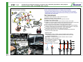
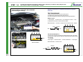
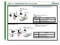
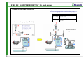
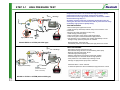
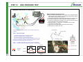
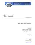
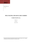
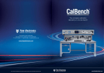
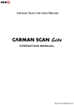
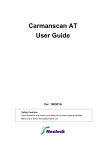
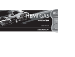
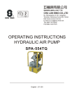
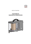
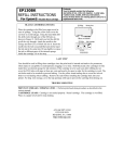
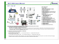
NCT-1000 Users Manual
NCT – 1000 KIT
11
NCT-1000 KIT
12
1
13
20
2
8
3
14
21
15
16
7
4
10
17
6
18
5
9
22
19
1. TOOL CASE
2. RAIL PLUG (12mm) 5ea (1 for spare)
3. RAIL PLUG (14mm) 5ea (1 for spare)
4. FLASK & HOLDER 1ea
5. VISIBLE TUBE 4ea
6. INJECTOR RETURN HOSE ADAPTER 4ea
7. INJECTOR RETURN HOSE PLUG (TUBE)
8. CLEAN CASE 1ea
9. DUST CAP
10. HIGH PRESSURE GAUGE with
PRV CONTROLLER
11. LOW PRESSURE GAUGE
12. VACUUM GAUGE
13. GAUGE CONNECTION TUBE
14. CONNECTION ADAPTER WITH HOSE
15. CONNECTION ADAPTER
16. FUEL FILTER PLUG( for Delphi system)
17. ADAPTER CONNECTOR ( for Bosch )
18. ADAPTER CONNECTOR (for Delphi New)
19. ADAPTER CONNECTOR (for Delphi Old)
20. DUMMY RESISTER
21. USER’S MANUAL
22. DUMMY RESISTER (HP Sensor)
This Tester has been developed to diagnose common rail diesel system efficiently and accurately.
1-1. CRITERIA OF DIAGNOSIS USING COMMON RAIL TESTER
Impossible to start engine or engine stall while driving
* NCT-1000 is not a INJECTOR TESTER. If vehicle has different symptoms such as engine vibration or black/white smoke emitting while engine idle, the
problem may due to unevenness injection from injectors. It would recommend to perform Power Balance Test (Injector quantity comparison) using scan
tool (Hi-Scan, GDS or G-Scan) or NCT-2000, Injector Tester.
1-2. DIAGNOSIS PROCEDURE ACCORDING TO SYMPTOM
1) When the engine is not able to start
① Injector Back Leak Test (Static Test) → ② Low Pressure Pump Test → ③ High Pressure Pump Test
2) When the engine is able to start
① Injector Back Leak Test (Dynamic Test) → ② Low Pressure Pump Test → ③ High Pressure Pump Test
CRDi system has many precision-made components. If any foreign particle (even extremely small) enters the system, it may cause to have injector clogging
or sticking. Therefore, make sure to protect fuel lines from any dust or contamination during service.
1
Conduct this test when the engine is not able to start, otherwise( if possible to start) skip this
test and conduct “STEP 1-2 DYNAMIC TEST” instead.
STEP 1-1
INJECTOR BACK LEAK TEST WITH STATIC
( Test with engine cranking)
Purpose of this test is to measure the amount of injector back leak
and to check the performance of High pressure pump.
* If injector back leak amount is too much High pressure pump’s
performance test will not be performed correctly. proceed Step 31 thru step 3-2 in this case.
8
2
1
TEST PROCEDURE
3
7
4
5
4
6
4
BOSCH EURO- 3 SYTEM (with PRV type)
2
2
Injector return
hose plug
1) Install the Back Leak tube① and the flask to injectors.
2) Block the fuel return hose② with plug.
3) Remove the wiring connectors from all Injectors and PRV.
4) Install the high pressure gauge.
5) Install the PRV dummy resistor to the connector of PRV control wire.
6) Install the HP sensor dummy resistor to the connector of HP sensor control wire.
Purpose of Dummy resister is to prevent fail safe mode by ECU.
7) Turn on the power supply switch⑦ of the high pressure gauge.
8) Crank the engine a few seconds to build high pressure and to do air bleeding.
Crank the engine again and measure the maximum high pressure of the pump
9) To prepare measuring back leak amount, empty visible tubes
removing the injector return hose adapter from injector.
10) Crank the engine once for 5 to 6 seconds and measure the back leak
amount from each visible tube.
SERVICE SPEC
High pressure : Above 700 bar ( with normal Back Leak condition)
※ Too much back leak amount leads rail pressure down and cause
insufficient high pressure.
Back Leak : Less than 3.5 times than minimum amount injector
CHECK POINT ( if test was failed )
- Fuel Leak (rail plug or pipes connection)
- PRV ( leakage or damaged )
- Fuel line ( clogging filter )
- HP pump (leakage or damaged)
4
3
2
1
2
STEP 1-2
Conduct this test when the engine is able to start, otherwise( if unable to start) skip this test
and conduct “STEP 1-1 STATIC TEST” instead.
Purpose of this test is to measure the amount of injector
back leak.
INJECTOR BACK LEAK TEST WITH DYNAMIC
(Test with engine running)
TEST PROCEDURE
1) Remove the fuel return hose from each injector
2) Install injector back leak test kit to the Injectors
3) Conduct the BACK LEAK test referring to following explanation.
BOSCH system
① Start engine → 1minute at idle →up to 3000rpm for 30sec → Stop
② Measure the amount of fuel in each test bottle
SERVICE SPEC : Less than 3.5 times than minimum amount injector
30sec / 3000rpm
Start
1min
stop
3
2
1
1
25cc
Injector
return hose
plug
1
2
3
2
3
4
DELPHI SYSTEM (HP 2.9)
①Connect the Hi-Scan and select the 'High Pressure Leak Test' mode.
②Conduct the 'High Pressure Leak Test' until the Hi-Scan finish the test
automatically.
or manually :
Start engine→ 2minutes at idle → 3 times acceleration → Stop engine
4
SERVICE SPEC : Less than 25cc
Normal Condition
3800rpm
2min
Start
Idle
Stop
acceleration
1
3
25cc
25cc
2
3
4
STEP 2-1 LOW PRESSURE TEST for each system
ELECTRIC PUMP TYPE
Purpose of this test is to check the condition of the
fuel line, blockage, performance of the feed pump, etc.
Pressure gauge
(Positive pressure Gauge)
Electric fuel pump
NOTE
- Only for Electric fuel pump type vehicles
EURO Ⅳ : 2 ~ 4.5 bar
OTHERS : 1.5 ~ 3 bar
Diagnostic factor
Symptoms
Fuel filter
• Immediate engine stall after initial starting
• Lack of engine power
Pump
SUCTION PUMP TYPE
Hard to start / Engine stall
NOTE
- Only for the Suction pump type Vehicles
SERVICE SPEC : 8 ~ 25 cm Hg
Pressure gauge
(Negative pressure Gauge)
BOSCHI
DELPHI
Suction pump
Diagnostic
factor
Fuel filter
Pump
4
Symptoms
• Immediate engine stall after initial starting
• Lack of engine power
Hard to start / Engine stall
STEP 2-2
LOW PRESSURE TEST for each system
INTERNAL SUCTION PUMP TYPE (DELPHI)
Purpose of this test is to check the condition of the
fuel line, blockage, performance of the feed pump, etc.
VACUUM
JUDGMENT
8~19 cmHg
System normal
20~60 cmHg
Filter or line clogging (pump OK )
0~7 cmHg
Air leak in to the system or Pump
problem
Block the return line
with plug
5
STEP 3-1
HIGH PRESSURE TEST
HIGH PRESSURE TEST WITHOUT INJECTOR
Rail Plugs
High pressure
sensor
Purpose of this test is to confirm the High pressure pump
performance and to reconfirm high pressure pump
performance when high pressure value is lower than 700bar
measured during Step 1-1.
Avoiding injector back leak completely by blocking the rail
outlet you can find out whether the lack of pressure was really
caused by high pressure pump faulty.
TEST PROCEDURE
- Remove the Injector pipes from the rail
- Install the dummy resistors(for PRV & HPS) to the connector of it’s
control wire.
- Block the rail outlet using RAIL PLUG ( 4 ea )
- Install the high pressure gauge
- Select mode switch of the gauge to Max High position
- Crank the engine to check the maximum High pressure
- If the pressure is over 1400bar stop cranking immediately to avoid
damage of High pressure pump due to overload.
High pressure Pump
SERVICE SPEC : Above 900 bar
If measured pressure is above 900bar,the high pressure is normal.
BOSCH EURO- 3 SYTEM (with PRV type)
TEST PROCEDURE
Rail Plugs
High pressure
sensor
- Remove the Injector pipes from the rail
- Removed the wiring connector of Inlet Metering Valve (IMV)
- Block the rail outlet using RAIL PLUG
- Install the high pressure gauge
- Selector mode switch of the gauge to Max High position
- Crank the engine to check the maximum High pressure
- If the pressure is over 1400bar stop cranking to avoid
damage of High pressure pump due to overload.
Disconnect
the IMV connector
SERVICE SPEC : Above 1000 bar
If measured pressure is above 1000bar,the high pressure is normal.
High pressure Pump
Not used
( Disconnect the HP
sensor connector)
DELPHI or EURO- 2 SYTEM (without PRV type)
6
Sensor problem
Low pressure
Normal
STEP 3-1
HIGH PRESSURE TEST
PRESSURE REGULATOR VALVE DIAGNOSIS
When assemble fuel pipe after test
1) Before connecting the fuel pipes to the engine, be sure that all the pipe
outlet surfaces, inner passages, and especially fuel pipe fitting nuts are
clean. Clean using air gun if necessary.
2) Assemble all fuel pipes except the fuel pipe fitting nuts of injector side.
3) Temporarily tighten the fuel pipe fitting nuts to injectors by hand .
4) To prevent contamination on engine room, wrap up around the injector
pipes using paper towel or shop rag as shown.
5) Crank the engine 2 - 3 times for 5 - 6 seconds to remove dusts
from injector connection area.
6) Tighten the nuts with specified torque using torque wrench.
7) Erase the DTC code by scan tool.
1
Fuel pipe end
Using HIGH PRESSURE GAUGE you can build or reduce rail
pressure.
Air gun nozzle
TEST PROCEDURE
1) Install the High Pressure controller & Tester
2) Select the MODE switch to HIGH mode
3) Crank the engine to build the high pressure
4) Turn on the power switch to create rail pressure and turn off
the switch to decay the pressure. Watch the response of needle
of gauge during the power switch is on and off .
Cleaning by air gun
Injector
Case 1 : Pressure drop delayed = Valve screen may clogged
Case 2 : Pressure was not increased or delayed = Valve leakage
Case # 1
Abnormal
Normal
Case #2
Current
Tighten the nuts
Paper towel
Pressure
7
Loosen the nuts
Valve clogging
Valve large
leak
Introducing CIT-2000 (injector Tester)
This new Injector Tester NCT- 2000 is developed in addition to CNCT-1000, in order to
improve diagnostic efficiency and accuracy for vehicles equipped with Common Rail
System.
CIT-2000 enables Injection Quantity Comparison Test under Low and High fuel pressure
conditions, which it was not possible with Hi-scan or NCT-1000.
Also Cylinder compression and Rail pressure regulator test are additionally available.
Tool supplier : Nextech Co., Ltd.
Contact Point : Mr. Alex Lim
Tel : +82-2-3140-1489 or 1443
Fax : +82-2-3140-1449
E-mail : [email protected]
Above all, most benefit is that you can show the real condition of Injector to customers.
1. INJECTOR TEST
2. COMPRESSION TEST
Injection quantity Comparison Test
You can estimate remaining
life time of Injector.
Cylinder Compression Comparison Test
3. PRV ACTUATION TEST
Pressure Regulator Valve Actuation Test,
PRV
Dummy injectors
with multiple adapter to cope
with variable injector type and
quick coupling for gauge
1
1
8