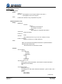
1
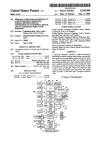
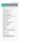
SignalTEK II User Guide 156810 issue 1 The information contained in this document is the property of IDEAL INDUSTRIES Ltd. and is supplied without liability for errors and omissions. No part of this document may be reproduced or used except as authorized by contract or other written permission from IDEAL INDUSTRIES Ltd. The copyright and all restrictions on reproduction and use apply to all media in which this information may be placed. IDEAL INDUSTRIES Ltd. pursues a policy of continual product improvement and reserves the right to alter without notice the specification, design, price or conditions of supply of any product or service. All rights reserved Publication ref: 156810 Issue 1 Issue 1 - 04/12 (Applies to software revision 1.0.0 onwards) IDEAL INDUSTRIES LTD. Stokenchurch House Oxford Road Stokenchurch High Wycombe Buckinghamshire HP14 3SX UK UK: France: Deutschland: International: +44 (0)1925 444446 [email protected] +33 1 69 35 54 70 [email protected] +49-(0)89-99686-200 [email protected] +44 (0)1925 444446 [email protected] Introduction ...............................................................................................................................................4 Care of your SignalTEK II .........................................................................................................................5 Final Disposal ...........................................................................................................................................5 Safety Information ....................................................................................................................................5 Connector Safety ...................................................................................................................................5 Power........................................................................................................................................................6 Power Module Management ..................................................................................................................6 Power Module Recharging.....................................................................................................................6 Battery Pack ...........................................................................................................................................6 Switching ON and OFF ..........................................................................................................................7 Power Saving .........................................................................................................................................7 Master Reset ..........................................................................................................................................7 Handset Controls, Indicators and Ports....................................................................................................8 Menu Navigation .......................................................................................................................................9 Soft Keys ..................................................................................................................................................9 Data entry .................................................................................................................................................9 Getting started ........................................................................................................................................10 Modes of Operation ................................................................................................................................10 Cable ....................................................................................................................................................10 Ethernet................................................................................................................................................10 Ports .......................................................................................................................................................12 Replaceable insert – RJ-45 socket ......................................................................................................12 Setup ......................................................................................................................................................13 Setup menu descriptions ........................................................................................................................14 Supported SFP Transceivers .................................................................................................................17 Tests modes ...........................................................................................................................................18 Cable mode ..........................................................................................................................................18 Ethernet mode .....................................................................................................................................18 Tests – run, setup and save ...................................................................................................................19 Tests menu description – Cable mode ...................................................................................................20 Wiremap ...............................................................................................................................................20 Tone .....................................................................................................................................................23 Autotest ................................................................................................................................................23 Tests menu description – Ethernet mode...............................................................................................24 Cable performance ..............................................................................................................................24 PoE ......................................................................................................................................................25 Blink .....................................................................................................................................................25 Ping4 and Ping6 ...................................................................................................................................26 TRoute4 and TRoute6 .........................................................................................................................26 Netscan ................................................................................................................................................27 VoIP .....................................................................................................................................................28 Web ......................................................................................................................................................29 Video ....................................................................................................................................................29 CCTV ...................................................................................................................................................29 Jobs ........................................................................................................................................................30 Using the Jobs menu ...........................................................................................................................31 Change the active Job .........................................................................................................................31 Managing Jobs .....................................................................................................................................32 Generating Reports ................................................................................................................................33 Specifications - SignalTEK II ..................................................................................................................34 Near-End Unit ......................................................................................................................................34 Remote Unit .........................................................................................................................................49 Glossary, abbreviations and acronyms ..................................................................................................54 SignalTEK II User Guide 156810 Iss 1 Page 3 SignalTEK II comprises two hand-held units and a set of standard accessories all held in a semi-rigid case. Two models are available, SignalTEK II and SignalTEK II FO. Both models are capable of performing the same range of tests. SignalTEK II has RJ45 connectivity; SignalTEK II FO has both RJ45 and Fiber connectivity. Fig 1 SignalTEK II components The Near-End unit is the terminal from where all tests are run and stored. The Remote Unit is a loopback terminal that enables performance testing. The Near-End Unit and Remote Unit are paired. When they are both connected to the same network, the Near-End Unit will find the Remote Unit that it is uniquely paired with, and not any other SignalTEK II Remote Unit that may be connected to the same network. The Near-End unit may be used as a stand-alone device for wiremap testing copper network cables. When both units are directly connected by a cable, wiremap and cable performance tests can be run. When the Near-End Unit is connected to a network, it can be used to carry out a range of IP tests. When both the Near-End and Remote Unit are connected to an active network, both IP tests and network performance tests are possible. This manual describes the operation and functions of the SignalTEK II FO. If you are using SignalTEK II please disregard all references to fiber optics. 156810 Iss 1 Page 4 SignalTEK II User Guide Although light and portable, the SignalTEK II units are robust and have been designed to operate in a protected outdoor working environment. To ensure reliable operation: Avoid very high or low temperatures - SignalTEK II is designed to operate between 0°C and +40°C, although you should only charge the batteries between +10°C and +30°C. You can store the unit safely between -20°C and +70°C. To avoid damage, when they are not in use we recommend that you keep both SignalTEK II units in their carrying case. Do not use solvents, strong detergents or abrasive materials to clean SignalTEK II. Use only cleaning agents approved for use on ABS and polycarbonate plastics. When your SignalTEK II has reached the end of its life you must dispose of both complete units in accordance with local environmental regulations. When using SignalTEK II, always take basic safety precautions to reduce the risk of fire, electric shock and injury to persons. These include the following: When connecting to the line, special care must be taken as high voltages may be present on the line and there may be a danger of electrocution. Avoid using SignalTEK II during an electrical storm - there is a remote risk of electric shock by lightning. Use only the mains electricity adaptor supplied with your SignalTEK II. CLASS 1 LASER PRODUCT. Light output from the fiber optic port can damage eyesight even though it is invisible. Never stare into open optical ports or the end of a fiber to see if light is coming out. Connector Safety The following connectors conform to EN60950 SELV safety status: RJ-45 Ethernet port. USB port. DC inlet port. DO NOT CONNECT ANY TELECOMMUNICATIONS NETWORK TO ANY OF THE TESTER’S PORTS SignalTEK II User Guide 156810 Iss 1 Page 5 SignalTEK II can be powered from: A rechargeable power module, Directly from power connected to the DC inlet built in to the power module. From an alkaline battery pack. The type of module or pack supplied as standard depends on the model purchased. Power Module Management A fully charged power module will support up to five hours of heavy, continuous use. For maximum life of the power module it is recommended to discharge it fully and then recharge it fully at least once a month. The power module is not user-serviceable. When it has reached the end of its life, contact your local IDEAL representative for service. Power Module Recharging The power module can be fully recharged in three hours with the SignalTEK II (either unit) switched ON or OFF. To recharge the power module, connect the supplied power adaptor to the DC inlet. For convenience the power module may be removed from, or left attached to, the unit for charging. The Power LED next to the DC inlet glows green to show that the battery is being charged, and flashes green to show that it is not being charged. The Near-End Unit’s power module charge state is indicated at FULL, 2/3, 1/3 and EMPTY by the graphical power meter shown in the display’s information bar at the top of its LCD display. Fig 2 Power indications The Remote Unit’s power module charge state is indicated by an LED directly below the Autotest key. LED indications are: Green Power ON. Battery level sufficient for use Red Power ON. Battery charge level low but still operational Off Power OFF Battery Pack Battery packs accept four replaceable AA alkaline cells. These cells cannot be recharged. 156810 Iss 1 Page 6 SignalTEK II User Guide Switching ON and OFF To switch ON the units, press the ON/OFF button. A splash screen showing the IDEAL logo and model identity is shown on the display. The Near-End unit attempts to detect a network and the Remote Unit. The home screen is then shown on the display. SignalTEK II is ready for use. To switch OFF either unit, press and hold the Power button for approximately 1/2 second, a shutdown message is displayed on the screen. The currently stored setup is saved. If the unit does not switch OFF within five seconds, see Master Reset. Always switch OFF the unit before removing the battery pack or power module. Power Saving Near-End Unit. Power saving preferences are selected from SETUP>SYSTEM>PREF. Auto Off can be Disabled (unit remains ON indefinitely), or set to switch the unit OFF after three, 10 or 30 minutes of inactivity. The backlight can be set to Always On, or to dim to 50% brightness after three minutes of inactivity. Note that when mains power is connected the display is always on full brightness and the unit remains ON indefinitely. Remote Unit. The remote unit remains ON indefinitely whether on battery or mains power. Master Reset In the unlikely event of a system lock-up which prevents the unit from being switched OFF, it may be necessary to perform a master reset. This will not delete any stored data. Remove the power module or battery pack to access a small aperture in the SignalTEK II (Fig 3). Insert a paper clip into the reset hole and press the internal reset switch. Fig 3 Replace the power module or battery pack. SignalTEK II User Guide 156810 Iss 1 Page 7 Fig 4 1 RJ 45 port 9 Function keys F1 to F3 17 Link LED 2 RJ 45 activity LED 10 Escape key 18 Status LED 3 RJ 45 link LED 11 Cursor and ENTER keys 19 1000 Mb/s line rate LED Optical port (SFP) 12 1 4 1 5 Optical activity LED 1 ON/OFF button 20 100 Mb/s line rate LED 2 Power module 21 10 Mb/s line rate LED 2 2 13 6 Optical link LED 14 Charger LED 22 Remote Autotest button 7 USB port 15 DC in connector 23 Power LED 8 LCD color display 16 Autotest button 1 Fig 4 items 4, 5 & 6 – SignalTEK II FO only. 2 Fig 4 item 13 shows optional power module. Note: The top, bottom and left hand side of both units are identical. 156810 Iss 1 Page 8 SignalTEK II User Guide Cursor and ENTER keys. The arrowed cursor keys are intuitively marked to move the highlighted field between all menu icons, settings fields and drop-down menus that appear on the display. ENTER selects the currently highlighted option. Escape key. Returns to previous screen or hides the options of a drop-down menu. Note that when a value in a settings field is changed, if the Escape key is pressed before the soft key ‘APPLY’, the value will not be stored. Autotest key. Immediately runs pre-stored range of tests. The range is easily changed using the SETUP menu. The Autotest keys on the Near-End and Remote Unit have identical function. Function keys. F1 to F3 are to select the corresponding soft keys at the lower edge of the display. Fig 5 The soft keys appear along the bottom edge of the display. Their function changes and is dependent on the screen currently shown on the display. When you navigate to and select a field that requires a value or text to be entered, such as a customer’s name or a URL, a QWERTY keyboard will be shown on the display (Fig 6). All data is entered using the QWERTY keyboard. Move the key that is highlighted on the keyboard using the tester’s cursor keys. ENTER selects the currently highlighted key which will now appear in the text window directly above the keyboard. Key stroke errors are corrected using the backspace key ( <− ). Press the UP cursor key to move the cursor into the text window for editing. Press the QWERTY keyboard’s SHIFT key to change the display from lower to upper case. Press SHIFT a second time to display symbols and punctuation characters. When the text or value has been entered, press the soft key OK (F1). The display will return to the previous screen which is now populated with the required data. You must press the soft key APPLY to save the changes. Fig 6 SignalTEK II User Guide 156810 Iss 1 Page 9 Press the soft key DETECT (F1) and the Near-End Unit will determine the mode of operation dependent on the services detected. The display will show a home screen with one of four connection symbols. There are two modes of operation, Cable and Ethernet. Cable has one way of connecting, Ethernet has three. Cable Cable mode is used for Wiremap testing and cable route tracing using the tone generator. When the Near-End Unit is connected to a copper cable, with or without an Active Remote, press the soft key DETECT (F1) to display all options available from the Cable mode screen. When an Active Remote is connected it will be shown on screen (Fig 7) and its identification number displayed. For a full description of these options, see Tests menu description – Cable mode. Fig 7 Ethernet Ethernet mode is used for a range of IP and performance tests. There are three ways to connect in Ethernet mode:(1) When the Near-End Unit and Remote Unit are directly connected, with copper or fiber cable, press the soft key DETECT (F1) to detect all options available (Fig 8). In addition to wiremap tests (copper), cable performance can be tested and measured. For a full description of these options see Tests menu description – Ethernet mode, page 24. Fig 8 156810 Iss 1 Page 10 SignalTEK II User Guide (2) When the Near-End Unit is connected to an active network, using copper or fiber cable, press the soft key DETECT (F1) to display all options available (Fig 9). IP tests can be run. For a full description of these options see – Tests menu description – Ethernet mode, page 25. The detected services are PoE (802.3af/at), ISDN, PBX and Unknown. The IPv4 and IPv6 addresses assigned to the tester are displayed (when available). Fig 9 (3) When both the Near-End Unit and Remote Unit are connected to an active network, using copper or fiber cables, press the soft key DETECT (F1) to display all options available (Fig 10). IP tests and performance tests can be run. For a full description of these options see – Tests menu description – Ethernet mode, page 28. The detected services are PoE (802.3af/at), ISDN, PBX and Unknown. The IPv4 and IPv6 addresses assigned to the tester are displayed (when available). Fig 10 SignalTEK II User Guide 156810 Iss 1 Page 11 From the home screen press the soft key PORTS (F2), highlight the required port and press ENTER (Fig 11). Tick the check box to always see this screen at startup. Testing over fiber is available with the SignalTEK II FO only. Fig 11 Replaceable insert – RJ-45 socket To replace a damaged or worn RJ-45 socket insert proceed as follows: Equipment required: Kit, IDEAL part number 150058 – includes Tool x1 and Replacement Insert x10. Switch the SignalTEK II OFF. Connect the tool to the socket insert that is to be replaced. Note the orientation of the insert within the socket and carefully remove it using the tool. Install the new insert to the socket using your fingers. Fig 12 156810 Iss 1 Page 12 SignalTEK II User Guide All user-defined settings and preferences of the SignalTEK II are set from the SETUP menu. A map of the SETUP menu is shown at Fig 13 and a description of the available settings and preferences is found on pages 14 to 17. Fig 13 SignalTEK II User Guide 156810 Iss 1 Page 13 From the home screen, press the soft key SETUP (F3) to display the Setup menu shown in Fig 14. The settings for all tests, functions and preferences can be changed and saved from here. Selecting any of the seven icons will produce the options that follow: Fig 14 Highlight the System icon and press ENTER to access the settings and preferences listed below: Enter your name or your company’s name, address and phone number(s). The details stored here will appear on all reports exported via a USB key. This option enables you to manage Jobs as follows: Create new Jobs. View, edit or delete existing Jobs. Save Jobs to a USB key. The ‘Activate’ icon selects the Job you require to be active. See Jobs for a full description. Sets the language for the tester. The on-screen display, and the exported results and reports will appear in the selected language. Sets the power saving options, the preferred units of length and the date and time formats. Export or import setup information to/from a USB stick. Use this function when you wish to copy setup information from one tester to another. Sets the current date and time. Note that the date and time are recorded against test results and will appear on exported reports. The internal clock is autonomous of the power module or battery pack for up to one day. For the Near-End Unit this menu item facilitates software updates downloaded from the IDEAL website and saved to a USB key. Select the update icon and follow the onscreen instructions. To update the Remote Unit: with unit switched OFF, insert USB key and then PRESS and HOLD the AUTOTEST key while switching on the unit. The LED’s will illuminate in sequence indicating that a software update is in progress. The unit reboots when the update is complete. Provides model, software, hardware and firmware information. Provides the option to return all settings to the factory default. The Near-End and Remote Unit must be paired after resetting to factory default. Refer to PAIR on page 17. A FACTORY RESET WILL REMOVE ALL STORED DATA AND PAIRING INFORMATION FROM THE TESTER 156810 Iss 1 Page 14 SignalTEK II User Guide Highlight the Tests icon and press ENTER to access the settings and preferences listed below: The two wiretests that follow are available :Set the cable type and color scheme to suit the cable to be tested, crossover allowed y/n, and NVP. NVP is preset at 72% but can be custom set anywhere in the range of 59 to 89% to suit the cable to be tested. Select from three tones. This avoids confusion when a second or third tester is being used on the same installation. Choose on which pin, or pin pair, to play the tone to achieve the best results. The six IP tests that follow are available :- Set the target URL/Numerical address (select from up to 10 targets stored in the v4 TARGET look up table or edit the currently displayed URL), Count (Number of times to repeat the Ping - 1 to 999999), Pause (Interval between successive Pings - 10 to 5000 ms), Length (Number of bytes in Ping frame payload - 8 to 1000 bytes). Set the target URL/Numerical address (select from up to 10 targets stored in the v4 TARGET look up table or edit the currently displayed URL), Maximum number of hops (2 to 100), Timeout (Abort timeout for any hop: 2 to 30 secs), Use a short timeout to reduce test time, or a long timeout to reach remote internet locations. Protocol (ICMP or UDP as required by your network). Select Name Lookup if supported by your network. If not required, de-select Name Lookup to reduce test time. Select whether the Netscan is to be Local (scan within the range of the tester’s own IP address) or Custom (scan within the range of the IP address configured). Set the Scan Range depending on whether a wide scan or a short test time is more important. Scan Range Max Number of Hosts Test time Class C/24 256 Short Class C/20 2048 Medium Class B/16 65,536 Long IPv6 Netscan Setup – None required (Automatically set). Select PoE or PoE Plus to suit your network. Set minimum power to be detected to suit the demand of your appliance. SignalTEK II User Guide 156810 Iss 1 Page 15 IP Tests continued Set the target URL/Numerical address (select from up to 10 targets stored in the v6 TARGET look up table or edit the currently displayed URL), Count (Number of times to repeat the Ping - 1 to 999999), Pause (Interval between successive Pings - 1 to 5 seconds), Length (Number of bytes in the Ping frame payload - 8 to 1000 bytes). Set the target URL/Numerical address (select from up to 10 targets stored in the v6 TARGET look up table or edit the currently displayed URL), Maximum number of hops (1 to 30), Timeout (Abort timeout for any hop - 2 to 30 secs), Select Name Lookup if supported by your network. If not required, de-select Name Lookup to reduce test time. The five performance tests that follow are available: Tick IEEE802.3 check box to set the frame failure threshold to 0 and the test duration to 10 secs. With the tick box unchecked the frame failure threshold and duration can be set manually to suit your test. The frame size is permanently set to 1518. Frame fill is always fixed. No. of Calls (Set expected number of simultaneous calls on the network – 1 to 10,000), Threshold (Frames) (Enter the number of errored frames acceptable – 0 to 99), Duration (Set test duration from 1 second up to 24 hrs). No. of sessions (Set expected number of simultaneous sessions on the network – 1 to 500), Threshold (Frames) (Enter the number of errored frames acceptable – 0 to 99), Duration (Set test duration from 1 second up to 24 hrs). Definition (Set to HD or SD), No. of Streams (Set expected number of simultaneous calls on the network – 1 to 70), Threshold (Frames) (Enter the number of errored frames acceptable – 0 to 99), Duration (Set test duration from 1 second up to 24 hrs). Resolution (Set to VGA, 720p, 1080p, 3MP or 5MP), CODEC (Set to H.264 or MJPEG), No. of Cameras (Set the number of cameras in the system), Threshold (Frames) (Enter the number of errored frames acceptable – 0 to 99). Select the tests that will run every time the Near-End or Remote Unit’s Autotest button is pressed. For details of the tests available, see Fig 34. Select this option to enter up to 10 IPv4 targets in a look up table. The targets you save here can be quickly selected when running Ping4 and TRoute4 tests. Select this option to enter up to 10 IPv6 targets in a look up table. The targets you save here can be quickly selected when running Ping6 and TRoute6 tests. 156810 Iss 1 Page 16 SignalTEK II User Guide Enable/disable IPv4 and set IP address as static or dynamic (DHCP) depending on which type your network supports. If Static is selected, enter the numerical address, Netmask, Gateway, DNS1 and DNS2. Enable/disable IPv6 and select address type as Static, Stateless, Stateful (DCHP) depending on which type your network supports. If Static is selected, enter numerical IP address, Prefix (64 or 128), Gateway, DNS1 and DNS2. The factory set MAC address of the tester is displayed. The skew between the Ethernet pairs is displayed. Skew is the delay (ns) between the arrival time of the four components of the Gigabit Ethernet signals. It is measured relative to the first signal to arrive, so that the displayed skew is always zero for at least one pair. Both MAC and skew data are displayed for information only. Provides the information that follows on the SFP connected to the Optical port: Status – Available or Not Fitted, Vendor, Part number, Rx Power (µW), Tx Power (µW). See Supported SFP Transceivers below. When first supplied, the Near-End and Remote units are paired. When a different or replacement Remote Unit is used, or the Near-End Unit has been RESET to factory default settings, select PAIR from the set up menu and press the soft key PAIR (F1). When the message ‘Remote detected’ is shown on the display the units are paired indefinitely. The SFP types that follow are supported. The use of other SFP types is possible but correct operation is not guaranteed. SX Avago AFBR-5705PZ 1Gb/s Multimode 850nm LC Duplex SX Apac LM28-C3S-TI-N-DD 1Gb/s Multimode 850nm LC Duplex LX Avago AFCT-5705PZ 1Gb/s Singlemode 1310nm LC Duplex LX Apac LS38-C3S-TC-N-DD 1Gb/s Singlemode 1310nm LC Duplex ZX Apac LS48-C3U-TC-N-DD 1Gb/s Singlemode 1550nm LC Duplex SignalTEK II User Guide 156810 Iss 1 Page 17 Testing with SignalTEK II falls into two modes, Cable and Ethernet. Cable mode Cable testing comprises of wiremap tests and a tone generator. When no network or SignalTEK II Remote Unit is detected, the home screen information bar will read ‘Cable’. When the TESTS icon is selected, the cable tests shown in the menu map at Fig 15 are available. Fig 15 Tests menu map – Cable testing Ethernet mode Ethernet testing is divided into three categories that are dependent on the services detected by the Near-End Unit. All available tests are illustrated in the three menu maps that follow (1) When a SignalTEK II Remote Unit is directly connected but no active network is detected, the home screen information bar will read ‘Ethernet’. When the TESTS icon is selected, the Ethernet tests shown in the menu map at Fig 16 are available. Fig 16 Tests menu map – Ethernet testing (1) (2) When an active network is detected but no SignalTEK II Remote Unit, the home screen information bar will read ‘Ethernet’ and when the TESTS icon is selected, the Ethernet tests shown at Fig 17 are available. Fig 17 Tests menu map – Ethernet testing (2) 156810 Iss 1 Page 18 SignalTEK II User Guide (3) When a SignalTEK II Remote Unit is detected through an active network the information bar will read ‘Ethernet’. When the TESTS icon is selected, the Ethernet tests shown at Fig 18 are available. Fig 18 Test menu map – Ethernet testing (3) To select a test highlight its icon and press Enter. Each test has its own result screen. This is indicated by the test name being shown in the display’s information bar. Press the soft key RUN (F1) to start the test. The test will use the setup criteria currently stored for that test. The F1 soft key changes to STOP, giving you the opportunity to abort the test. When you want to change the setup criteria before a test is run, press the soft key SETUP (F3). The display will show a screen where all variables for the test can be changed. Press the soft key APPLY (F2) to save the changes and return to the result screen. For all tests a symbol is displayed at the top right hand corner of the screen below the clock in the display’s information bar. Indicates test has not been run and that the tester is ready. Will be displayed if the test is aborted, or when a test has been run and a fault detected or a network is unknown or unreachable. Indicates test is in progress. This symbol is also displayed while the tester is detecting a port. Indicates a test has been run with no faults detected. When a test is complete the results will be displayed; the soft keys now read RUN, SAVE and SETUP. You can save the results now or press Escape to return to the Tests screen and select another test to run. The results of the previous test are not lost unless you wish to discard them by pressing the soft key RESET (F1). This arrangement gives you the choice of saving the results of either one or several tests to a single Result. To find out how Results are stored, see the description of ‘Jobs’ on page 30. Press the soft key SAVE (F2) and the Save Results screen is displayed. Dropdown menus give you the choice of which job and result you would like to store the test under. The remaining storage capacity is displayed as a percentage. For a full description of the storage of test results see Jobs. SignalTEK II User Guide 156810 Iss 1 Page 19 When the TESTS icon from the cable mode home screen is selected, Fig 19, the available tests will be displayed, Fig 20. Fig 19 Fig 20 After any one of the three available tests from the menu is selected, the soft keys RUN and SETUP will appear: Wiremap When the soft key RUN (F1) is pressed a wiremap test will be run on the cable currently connected to the tester’s RJ45 port. The settings used for the test will be those that have been preset via the setup menu: SETUP>TESTS>WIRETEST>WIREMAP. After the test has been run, the display will show a graphical interpretation of the result (Fig 21) and an indication of the distance to the fault or, the length of the cable. In addition, a FAULT icon and a SAVE soft key will appear. Select the FAULT icon and the display will show a textual list of the faults detected, Fig 22. Fig 21 156810 Iss 1 Page 20 Fig 22 SignalTEK II User Guide Note that for the example of a Wiremap test shown above; if the option ‘XOver Allowed’ had been checked in the Wiremap SETUP options, the results would be displayed as shown in Fig 23 and Fig 24. Fig 23 Fig 24 The wiremap tests may be run with no termination – open, or with an Active Remote termination. When connected, an image of an Active Remote will be shown on the display and its type identified. After a test has been run, the length of the cable is displayed (range up to 100m (330ft)). With an open termination the possible faults detected are: Fig 25 Open circuit by pair SignalTEK II User Guide Fig 26 Short circuit by pin 156810 Iss 1 Page 21 With an Active Remote or a SignalTEK II Remote Unit termination the possible faults detected are: Fig 27 Open circuit by pin Fig 28 Short circuit by pin Fig 29 Crossed pairs Fig 30 Split pairs Fig 31 Bridged shorts Fig 32 Remote shorts As with the result of the Crossover fault shown in Fig 21 and Fig 22, all wiremap test results are displayed as a graphic that includes the FAULT icon. When the icon is selected, the faults are presented as a list. The indications that follow appear on the Active Remote device: Flashing green LED – Test Passed. Flashing red LED – Test Failed. Amber LED – DC voltage greater than 12 Volts detected – cannot perform test. 156810 Iss 1 Page 22 SignalTEK II User Guide Tone SignalTEK II can act as a tone generator (Fig 33). Together with a compatible tone probe, the route of a cable can be traced. A choice of three tones can be selected. To achieve the best result, the tone may be played over one of eight pins relative to the other seven, or over one of four pairs. The tone is started and stopped with the F1 soft key which displays as RUN or STOP accordingly. Press the soft key SETUP (F3) to change the tone and the pin, or pin pair, that the tone is played on. Press the soft key APPLY (F2) for your changes to take effect. Fig 33 Autotest SignalTEK II can be set up to run a predefined range of tests when the yellow Autotest button is pressed on either the Near-End or Remote Unit. The range of tests is set from SETUP>TESTS>AUTOTEST by ticking the check boxes next to your choice, Fig 34. Press the soft key APPLY (F2) for your changes to take effect. Fig 34 When an Autotest is run, Fig 35, the display lists the tests that are applicable to the current mode from the list that you selected at Setup and shows the status of each. After the Autotest is complete, or has been stopped, each individual test can be selected and its detailed results displayed. In Cable mode, Autotest is limited to Wiremap. Fig 35 SignalTEK II User Guide 156810 Iss 1 Page 23 When a SignalTEK II Remote Unit is directly connected but no active network is detected, select the TESTS icon from the home screen (Fig 36) to view the tests available, Fig 37. Fig 36 Fig 37 After any one of the three available tests is selected from the menu, the soft keys RUN and SETUP will appear: Wiremap and Autotest are described in Tests menu description – Cable mode. When Wiremap is run in Ethernet mode, the only difference is that the cable to be tested is not connected to an Active Remote but to either the Remote Unit or an active network port. Cable performance When a cable performance test is run, back-to-back frames are transmitted to the Remote Unit which loops them back to the Near-End Unit where they are checked and counted. Fig 38 156810 Iss 1 Page 24 Fig 38 shows the result screen of a successful cable test. Frame Size, which is fixed, is stated for information. Tx states the number of frames transmitted, the associated green indicator bar confirms that 100% of the frames were sent. As the frame size (and fill) is fixed, the number of frames transmitted is dependent on the duration of the test only. Rx states the number of frames received, the green indicator bar confirms that 100% of the transmitted frames were received. As all transmitted frames were received, Error states 0 and its associated indicator bar remains uncolored and shows 0%. When there is a discrepancy between the number of transmitted and received frames, Error states the number of errored frames and the indicator bar is partly colored red proportional to the number of errored frames. However, the cable will still pass the test provided the Frame Threshold is not exceeded (see Setup page 16). SignalTEK II User Guide When an active network is detected but no SignalTEK II Remote Unit, select the TESTS icon from the home screen (Fig 39) and the Tests screen (Fig 40) is displayed. In addition to Autotest, (described in Tests menu description – Cable mode) POE and Blink tests can be run from here. Select the IP TEST icon to reach the IP tests Ping, Trace route and Netscan (Fig 41). Fig 39 Fig 40 Fig 41 PoE When the Near-End Unit is connected to a port it automatically detects PoE voltage (when present). In addition, running a PoE test will apply a resistive load and measure the power available at the connected port. SignalTEK II identifies which pairs are carrying power, and displays the voltage(V), current(mA) and power(W). The PoE test result screen at Fig 42 shows that pair one and two, and pair three and six are carrying 11 Watts. The port tested is capable of powering devices that require upto 11 Watts. Fig 42 The test is PASSED because the power available is ≥ the minimum power value entered at set up. Blink A Hub Blink test forces the connected port of a network device to blink. SignalTEK II also changes the speed and therefore LED color (on supporting devices) making it easier to identify the correct port. Select the BLINK icon from the Tests screen, the test is started and stopped with the soft key F1 which displays as RUN or STOP accordingly. SignalTEK II User Guide 156810 Iss 1 Page 25 Ping4 and Ping6 Ping will test the availability and measure the response times of devices and URLs. The results of a successful test, both in progress and passed are shown in Fig 43. The range of possible results are listed next to the figure. Info: READY, IN PROGRESS, PASSED, NO RESPONSE, UNKNOWN HOST. Tx: Count of transmitted ping frames: 1 to 999999. Rx: Count of successfully received Ping responses: 1 to 999999. Delay: Round trip delay in ms between transmitting Ping and receiving response. Displayed as Minimum, Average and Maximum. Fig 43 TRoute4 and TRoute6 Trace Route will display the route and measure transit delays of frames across an IP network. Press the soft key SETUP (F3) to enter the target or select one from the v4 or v6 TARGET look-up table, and to view or amend the test settings. Select an individual hop to view its statistics. The soft keys PREV (F1) and NEXT (F3) and are used to navigate between individual hops. Each hop is traced three times. The time recorded during each trace is displayed in ms as T1, T2 and T3. Fig 44 156810 Iss 1 Page 26 SignalTEK II User Guide Netscan Netscan will report the number of IPv4 hosts and IPv6 hosts detected within the scan range. Press the soft key SETUP (F3) to adjust the scan settings if required. Fig 45 SignalTEK II User Guide 156810 Iss 1 Page 27 When a SignalTEK II Remote Unit is detected through an active network, select the TESTS icon from the home screen (Fig 46) to display the Tests screen (Fig 47). From the Tests screen select the IP TEST icon to show the IP Tests screen (Fig 48), or select the DATA icon to show the Performance Tests screen (Fig 49). The IP Tests are as described on pages 26 and 27. Each of the performance tests operate on the principle that follows: (1) Frames transmitted to Remote Unit at calculated Frame Rate for specified duration, (2) Frames looped back by Remote Unit, (3) Received frames checked and counted. Fig 46 Fig 47 Fig 48 IP Tests Fig 49 Performance Tests Before a Performance test is run, the warning and dialogue that follow are displayed: This test will generate traffic loading which may interfere with other network users CONTINUE? YES/NO Select YES to continue with the test and not display the warning again until the next power cycle. Select NO to not continue with test and display the warning again before another test is run. Performance tests are as follows: VoIP Fig 50 shows the result screen of a successful VoIP test. Frame Size and Frame Fill are fixed, and stated for reference only. The Information rate, IR (Mb/s), is variable and dependent on the number of calls you have entered at set up. Tx states the number of frames transmitted, the green indicator bar confirms that 100% of the frames were sent. Rx states the number of frames received, the green indicator bar confirms that 100% of the transmitted frames were received. As all transmitted frames were received, Error states 0 and its associated indicator bar remains uncolored and shows 0%. Fig 50 156810 Iss 1 Page 28 SignalTEK II User Guide Web Fig 51 shows the result screen of a successful Web test. Frame Size and Frame Fill are fixed, and stated for reference only. The Information rate, IR (Mb/s), is variable and dependent on the number of sessions you have entered at set up. Tx states the number of frames transmitted, the green indicator bar confirms that 100% of the frames were sent. Rx states the number of frames received, the green indicator bar confirms that 100% of the transmitted frames were received. As all transmitted frames were received, Error states 0 and its associated indicator bar remains uncolored and shows 0%. Fig 51 Video Fig 52 shows the result screen of a successful Video test. Frame Size and Frame Fill are fixed, and stated for reference only. The Information rate, IR (Mb/s), is variable and dependent on the number of streams entered and the definition chosen at set up. Tx states the number of frames transmitted, the green indicator bar confirms that 100% of the frames were sent. Rx states the number of frames received, the green indicator bar confirms that 100% of the transmitted frames were received. As all transmitted frames were received, Error states 0 and its associated indicator bar remains uncolored and shows 0%. Fig 52 CCTV Fig 53 shows a CCTV performance test in progress. Frame Size and Frame Fill are fixed, and stated for reference only. The Information rate, IR (Mb/s), is variable and dependent on the Resolution, CODEC and number of cameras chosen at set up. Tx shows that, so far, 72,371 frames have been transmitted which is 92% of the total frames required to be sent in this test. Rx shows that only 62,405 of the transmitted frames have been received (79% of the total sent so far). Error shows the number of errored (unreturned) frames (Approx. 12%). When the number of errored frames is ≥ the Threshold (Frames) that you entered at set up, the test is failed. Fig 53 SignalTEK II User Guide 156810 Iss 1 Page 29 SignalTEK II provides a system that enables the storage and organization of test results and statistics. Test results can be exported via a USB key and used to produce reports. The two elements of this storage and organization system are Jobs and Results. A Job is a named repository for a collection of Results. A Result is a group of test results. It may contain the saved results of one or several tests. Therefore, a Job may be understood as a folder, a Result as the file(s) held within that folder. SignalTEK II can store up to 10 Jobs each containing 250 Results. At any time, one Job is always ‘active’. Any existing Job can be activated, at any time, via the menu on the Jobs Options screen. The currently active Job is indicated in the display’s information bar. Test results are saved by pressing the soft key SAVE (F2). The Save Result screen is displayed. From here you may choose which Job to save the test(s) to and, the prefix and serial number of the Result. If you do not choose, SignalTEK II defaults to the active Job and assigns the next serial number. The structure in which Jobs, Results and test results are stored is shown in Fig 54. Fig 54 Example of Job storage structure When creating a new Job, you can store: The customer’s contact, address and telephone details. This information will appear on reports that are compiled from exported test results. A prefix (relates to all associate Results). It will appear at the front of every Result number, e.g. ABC0001, where ABC is the user-defined prefix and 0001 is the system-allocated Result number. The prefix must be an alphanumeric string (no spaces or punctuation). Adding a prefix for Result numbers is optional. A Job title (user defined). Enables Jobs to be named. The Job title must be an alphanumeric string (no spaces or punctuation). 156810 Iss 1 Page 30 SignalTEK II User Guide Using the Jobs menu From the home screen select the JOBS icon. The display will show the Job List screen, Fig 55. The Job List screen lists all currently stored Jobs. The column ‘Tests’ indicates the number of Results saved to each Job. The column ‘Pass %’ indicates the percentage of the total number of tests in all Results allocated to a Job that have passed. Fig 55 Job List screen Change the active Job In the example of a Job List screen shown at Fig 55, the active Job is ‘Acme’ as indicated on the display’s information bar. To change the active Job, scroll to the Job required (e.g. My Job) and press the soft key OPTIONS (F2); the display will show the Options screen, Fig 56. Highlight the ACTIVATE icon and press ENTER. The display will show a dialogue stating: ‘MyJob is set as current job’ To change the active Job List from Acme to MyJob Press ENTER to confirm. The display returns to the Job List screen, and the new active Job is now shown in the information bar. Fig 56 Options screen SignalTEK II User Guide 156810 Iss 1 Page 31 Managing Jobs Select one of the icons from the Job List screen to manage Jobs as follows: Create a new Job. Up to five Jobs can be stored. Data entry fields are: Prefix. Enter an alphanumeric string which will be prefixed to all Results stored under the new Job. Job. Enter an alphanumeric string which will be the title of the new Job. For example, your customer’s name. Customer details. Fields are provided for – Company, Address, City, State, ZIP, Phone No. When a new Job is created it automatically becomes the Active Job. Amend any details of an existing Job. Press the soft key APPLY (F2) to save the changes. Delete a Job and all its associated Results. When DELETE is selected, the dialogue ‘Are you sure you want to delete ‘Job’ will appear. ONCE DELETED, A JOB CANNOT BE RESTORED Selects the Job to be currently active. All test results are saved to the active Job. Full details of this function are described on page 31. When selected, the display will show the Results screen. The Results are shown as a list and can be viewed, deleted or exported to a USB key. The soft key SHOW (F2) toggles between Status (pass/fail), and the Date and Time that the test was saved. Exports the active Job List to USB. Information on how to generate reports is detailed below. 156810 Iss 1 Page 32 SignalTEK II User Guide Reports can be generated using test results exported via a USB key. To generate a report: Insert a USB key into the SignalTEK II USB port. From the home screen select the JOBS icon. The display will show the Job List screen. Highlight the Job to be exported and press the soft key OPTIONS (F2). The display will show the Options screen. Highlight the TO USB icon and press Enter. The dialogue ‘Result saved to USB’ appears. Alternatively, an individual Result from a Job may be exported: Insert a USB key into the SignalTEK II USB port. From the home screen select the JOBS icon. The display will show the Job List screen. Highlight the Job required and press ENTER. The display shows all Results contained within the Job. Highlight the Result you require and press the soft key TO USB (F3). The dialogue ‘Result saved to USB’ appears. Test results and statistics are now saved on the USB key and can be viewed as a report on any PC installed with Microsoft Internet Explorer™ version 8, Mozilla Firefox™ version 9 or other suitable browser. Two files are saved to the USB key, the test results are stored as an XML document and a report template is stored as an XSLT file. Open the XML document to view the report. SignalTEK II User Guide 156810 Iss 1 Page 33 The specifications listed below are for the SignalTEK II FO. SignalTEK II has identical function but is fitted with a copper (RJ45) port only. Near-End Unit Connectors Test Ports RJ45 Used for - Cable Test (With a companion Remote Unit) - Network Test (Connected to an active network) Connector type - Samtec Lifejack with user-replaceable contacts Insertion Cycles - 500 min Location - Left hand side Optical Used for - Cable Test (With a companion Remote Unit) - Network Test (Connected to an active network) Connector type - SFP socket Location - Left hand side System Ports USB Used for - Software Update - Results transfer Class - Host Connector type - A USB type - 1.1 Location - Top Power Used for - Battery charging - Mains powering via adaptor Connector type - 2.5mm pin power jack Polarity - Centre pin positive Voltage - 12v Current - 2 amp Location - Bottom of power module (Not present in alkaline battery pack) Controls ON/OFF Push button Used for - Power ON/OFF Location - Front Function Keys F1 to F3 Used for - Screen-defined functions Location - Front Navigation Keys Cursor and ENTER Used for - User interface navigation Location - Front (continued) 156810 Iss 1 Page 34 SignalTEK II User Guide Controls (continued) Navigation Keys Escape Used for - Return to previous menu Location - Front Autotest Used for - Launch of automatic test sequence Location - Front Reset Push button Used for - Escape from exceptional lockup condition Location - Accessible through hole inside battery compartment using paper clip Displays Screen LCD Used for - Display of setup functions and results Location - Front Size - 2.8 inch diagonal Type - QVGA Color Pixels - 240 x 320 LEDs Charger LED Used for - Indication of charging status… Green - Battery is charging Off (with charger connected) - Battery is charging Green flashing - Battery is not being charged Color - Green Location - Bottom of Power module (Not present in alkaline battery pack) RJ45 Link LED Use - ON indicates link UP Location - Adjacent to RJ45 socket, nearest top of tester Color - Green RJ45 Activity LED Use - Flashing indicates link activity Location - Adjacent to RJ45 socket, nearest bottom of tester Color - Green Optical Link LED Use - ON indicates Optical link UP Location - Adjacent to SFP socket, nearest front of tester Color - Green Optical Activity LED Use - Flashing indicates Optical link activity Location - Adjacent to SFP socket, nearest back of tester Color - Green SignalTEK II User Guide 156810 Iss 1 Page 35 Ports RJ45 Fixed Setup Speed – Auto negotiated Duplex – Auto negotiated MAC – Factory set Tests Automatic mode selection depending on detection of Network / Remote Unit: No-Link (No network or Remote Unit detected) Link (Active network detected but no Remote Unit) Link-Remote (Remote Unit detected through a network device) Remote (Remote Unit detected but no network) Active Remote (Active remote #1 - #12 detected) Link Mode Tests (Active network detected but no Remote Unit) - IPv4 Ping - IPv6 Ping - Traceroute v4 - Traceroute v6 - Netscan - PoE / PoE+ Load - Hub Blink - Auto IPv4 Ping IPv6 Ping Traceroute v4 Traceroute v6 Netscan PoE / PoE+ Load Remote Mode Tests (Remote Unit detected but no network) - Double-ended Wiremap - Cable Performance - Auto Double-ended Wiremap Cable Performance Link-Remote Mode Tests (Remote Unit detected through a network device) - VoIP Performance - Web Performance - Video Performance - CCTV Performance - IPv4 Ping - IPv6 Ping - Traceroute v4 - Traceroute v6 - Netscan - PoE / PoE+ Load - Hub Blink (continued) 156810 Iss 1 Page 36 SignalTEK II User Guide Ports (continued) RJ45 Tests - Auto VoIP Performance Web Performance Video Performance CCTV Performance IPv4 Ping IPv6 Ping Traceroute v4 Traceroute v6 Netscan PoE / PoE+ Load Active Remote Mode Tests (Active Remote #1 - #12 detected) - Double-ended Wiremap - Tone Generator - Auto Double-ended Wiremap No-Link Mode Tests (No network or Remote Unit detected) - Single-ended Wiremap - Tone Generator - Auto Single-ended Wiremap Service Detection Detected Services - PoE / PoE+ (802.3af/at. Not Cisco pre-standard) - ISDN - PBX - Unknown Optical Supported SFPs The following SFP types are supported. Use of other types of SFP is possible but correct operation is not guaranteed. SFP Type SX Manufacturer Part # - Avago AFBR-5705PZ / Apac LM28-C3S-TI-N-DD Speed - 1Gb/s Fiber Type - Multimode Wavelength - 850nm Connector Type - LC Duplex SFP Type LX Manufacturer Part # - Avago AFCT-5705PZ / Apac LS38-C3S-TC-N-DD Speed - 1Gb/s Fiber Type - Singlemode Wavelength - 1310nm Connector Type - LC Duplex SFP Type ZX Manufacturer Part # - Apac LS48-C3U-TC-N-DD Speed - 1Gb/s Fiber Type - Singlemode Wavelength - 1550nm Connector Type - LC Duplex (continued) SignalTEK II User Guide 156810 Iss 1 Page 37 Ports (continued) Optical Setup Speed MAC - 1Gb/s - Factory set Indication Optical power indicated on home screen if supported by fitted SFP Tests Automatic mode selection depending on detection of Network / Remote Unit: No-Link (No network or Remote Unit detected) Link (Active network detected but no Remote Unit) Link-Remote (Remote Unit detected through a network device) Remote (Remote Unit detected but no network) Active Remote (Active remote #1 - #12 detected) Link Mode Tests (Active network detected but no Remote Unit) - IPv4 Ping - IPv6 Ping - Traceroute v4 - Traceroute v6 - Netscan - Hub Blink - Auto IPv4 Ping IPv6 Ping Traceroute v4 Traceroute v6 Netscan Remote Mode Tests (Remote Unit detected but no network) - Cable Performance - Auto Cable Performance Link-Remote Mode Tests (Remote Unit detected through a network device) - VoIP Performance - Web Performance - Video Performance - CCTV Performance - IPv4 Ping - IPv6 Ping - Traceroute v4 - Traceroute v6 - Netscan - Hub Blink - Auto VoIP Performance Web Performance Video Performance CCTV Performance IPv4 Ping IPv6 Ping Traceroute v4 Traceroute v6 Netscan 156810 Iss 1 Page 38 SignalTEK II User Guide Cable Tests Wiremap Setup Cable Type – Cat3 UTP Color Scheme - Cat3 STP - Cat5 UTP - Cat5 STP - Cat5e UTP - Cat5e STP - Cat6 UTP - Cat6 STP - Cat7 - USOC - ETH S1236 - ETH S1278 - ETH U1236 - ETH U1278 - IND. M12 - COAX RG59 - None - 568A - 568B - USOC - TERA Crossover Allowed - Yes - No NVP - Fixed 72% - Custom 59% - 89% Termination Types supported and identified by icon Active Remote - #1 - #12 Remote Unit Single-ended Wiremap Tests Faults - Open circuit by pin - Short circuit by pin Length of pair - Meters / Feet (Set in System Setup) - Range 100m / 390ft Double-ended WiremapTests I/D - Active Remote # / Remote icon Indications on Active Remote - Voltage Warning (>±10v on any pins) - Pass/Fail Indications on Remote Unit - See below Faults - Open circuit by pin - Short circuit by pin - Crossed pairs - Split pairs - Bridged shorts - Remote shorts Length of pair - Meters / Feet (Set in System Setup) - Range 100m / 390ft Delay Skew - Per pair (ns) (continued) SignalTEK II User Guide 156810 Iss 1 Page 39 Cable Tests (continued) Tone Generator Setup Tones - 3 Wire I/D - Tone applied to one of 8 pins relative to the other 7 - Tone applied across one of 4 pairs Test Audible tone detected using compatible tone probe Cable Performance Test Setup IEEE802.3 Tick-box Ticked Fix Failure Threshold at 0 Fix Duration at 10 secs Unticked Allow editing of Threshold and Duration Frame size Fixed 1518 bytes Frame Fill Fixed Duration User-defined (hh:mm:ss up to 24 hours. Default 10 secs) Failure Threshold Number of frames (0 to 9999. Default 0) Test - Back-to back frames transmitted to Remote for specified duration. - Remote loops frames back - Received frames checked and counted Results Test conditions Line Rate 10 Mb/s 100 Mb/s 1000 Mb/s Duplex Full Half Frame Size Frame Fill Overall result Pass (100% frames transmitted, 100% frames received and Failure threshold not exceeded) Fail Transmitted Frames 12 Count (0 to 10 ) Percentage (0 to 100% with colored bar indication - green if 100%, red if <100%) Result Pass (100%) Fail (<100%) (continued) 156810 Iss 1 Page 40 SignalTEK II User Guide Cable Tests (continued) Cable Performance Test Results Received Frames 12 Count (0 to 10 ) Percentage (0 to 100% with colored bar indication - green if 100%, red if <100%) Result Pass (100%) Fail (<100%) Errored Frames 12 Count (0 to 10 ) Percentage (0 to 100% with colored bar indication. Green if below threshold, red if > threshold) Result Pass (<threshold) Fail (> threshold) Link-Remote Performance Tests VoIP Performance Test Fixed Settings Frame size Fixed 218 bytes Frame Fill Random Setup Number of Simultaneous Calls User-defined. (Range 1 to 10,000 . Default 100) Equivalent Information Rate calculated and displayed Duration User-defined (hh:mm:ss upto 24 hours. Default 10 secs) Failure Threshold Number of frames (0 to 99. Default 0) Test - Frames transmitted to Remote at calculated Frame Rate for specified duration - Frames looped back by Remote - Received frames checked and counted (continued) SignalTEK II User Guide 156810 Iss 1 Page 41 Link-Remote Performance Tests (continued) VoIP Performance Test Results Test conditions Line Rate 10 Mb/s 100 Mb/s 1000 Mb/s Information Rate Mb/s Duplex Full Half Frame Size Frame Fill Overall result Pass (100% frames transmitted and Failure threshold not exceeded) Fail Transmitted Frames 12 Count (0 to 10 ) Percentage (0 to 100% with colored bar indication - Green if 100%, red if <100%) Result Pass (100%) Fail (<100%) Received Frames 12 Count (0 to 10 ) Percentage (0 to 100%) Errored Frames 12 Count (0 to 10 ) Percentage (0 to 100% with colored bar indication -, Green if 100%, red if <100%) Result Pass (100%) Fail (>100%)) Web Performance Test Fixed Settings Frame size Fixed 1518 bytes Frame Fill Random Setup Number of Simultaneous Sessions User-defined. (Range 1 to 500. Default 10) Equivalent Information Rate calculated and displayed IR = 1.8 x No of sessions (Mb/s) Equivalent Frame Rate calculated but not displayed FR = IR / 1518 / 8 (fps) Duration User-defined (hh:mm:ss upto 24 hours. Default 10 secs) Failure Threshold Number of frames (0 to 99. Default 0) (continued) 156810 Iss 1 Page 42 SignalTEK II User Guide Link-Remote Performance Tests (continued) Web Performance Test Test See VoIP Performance Test Results See VoIP Performance Test Video Performance Test Fixed Settings Frame size Fixed 1518 bytes Frame Fill Random Setup Definition SD HD Number of Simultaneous Video Streams User-defined. (Range 1 to 70. Default 1) Equivalent Information Rate calculated and displayed Duration User-defined (hh:mm:ss upto 24 hours. Default 10 secs) Failure Threshold Number of frames (0 to 99. Default 0) Test See VoIP Performance Test Results See VoIP Performance Test CCTV Performance Test Fixed Settings Frame size Fixed 1518 bytes Frame Fill Random Setup Resolution VGA 720p 1080p 3MP 5MP CODEC H.264 MJPEG (continued) SignalTEK II User Guide 156810 Iss 1 Page 43 Link-Remote Performance Tests (continued) CCTV Performance Test Setup Number of Cameras User-defined. (Range 1 to 500. Default 1) Equivalent Information Rate calculated and displayed Duration User-defined (0 to 99 secs. Default 10 secs) Failure Threshold Number of frames (0 to 99. Default 0) Test See VoIP Performance Test Results See VoIP Performance Test Network Setup IPv4 Setup Addressing - DHCP - Static Numerical - Address - Netmask - Gateway - DNS1 - DNS2 IPv6 Setup Addressing - Stateful (DHCPv6) - Stateless - Static Numerical - 128bit HEX IP address Network Prefix - 64 bit - 128 bit Network Tests Pingv4 Setup Target Count Pause Length - Numerical address - URL (Store up to 10) - 1 to 999999 - 1 to 5 Sec - 8 to 1000 bytes. Results Info Tx Count Rx Count Delay(ms) 156810 Iss 1 Page 44 - READY - IN PROGRESS - PASSED - NO RESPONSE - UNKNOWN HOST - 1 to 999999 - 1 to 999999 - Minimum SignalTEK II User Guide - Average - Maximum Pingv6 Setup Target Count Pause Length - IPv6 address - URL (Store up to 10) - 1 to 999999 - 1 to 5 Sec - 8 to 1000 bytes. Results Info Tx Count Rx Count Delay(ms) - READY - IN PROGRESS - PASSED - NO RESPONSE - UNKNOWN HOST - 1 to 999999 - 1 to 999999 - Minimum - Average - Maximum Traceroutev4 Setup Target Max Hops Timeout Type - Numerical address - URL (Store up to 10) - 1 to 30 - 2 to 30 sec - ICMP - UDP (continued) SignalTEK II User Guide 156810 Iss 1 Page 45 Network Tests (continued) Traceroutev4 Results Info - READY - IN PROGRESS - PASSED - NO RESPONSE - UNKNOWN HOST - Numerical address - t1 - t2 - t3 Hop Delay(ms) Traceroutev6 Setup Target - Numerical address - URL (Store up to 10) - 1 to 30 - 2 to 30 sec - UDP Max Hops Timeout Type Results Info - READY - IN PROGRESS - PASSED - NO RESPONSE - UNKNOWN HOST - Numerical address - t1 - t2 - t3 Hop Delay(ms) Netscan Setup Address Type Scan Range - Local - Custom IPv4 address - 0 (class C /24) - 1 (class C /20) - 2 (class B /16) Results - Total of IPv4 hosts - Total of IPv6 hosts Blink Test Sequence 156810 Iss 1 Page 46 - Off/10/Off/100/Off/1000 Mb/s (RJ-45) - Off/On (Optical) SignalTEK II User Guide Storage Configurations Internal storage Number of configurations - 2 (Current & Factory settings) Results Internal storage Max Number of Jobs (Projects) - 10 Max Number of result sets per Job - 250 Max total number of result sets - Up to 2500 depending on tests performed. Results stored Where available - Wiremap - Cable Performance - VoIP Performance - Web Performance - Video Performance - Netscan - PoE Load - info: listening, assigned, DHCP failed - DHCP or Static - IPv4 Address - IPv4 Netmask - IPv4 Gateway - IPv4 DNS1 - IPv4 DNS2 - info: listening, assigned, DHCP failed - Stateful (DHCPv6) or Stateless or Static - IPv6 Address - IPv6 Network Prefix, 64 bit or 128 bit - IPv6 Link Address - IPv6 DNS (continued) SignalTEK II User Guide 156810 Iss 1 Page 47 Storage (continued) Export Port - USB Format - .xml PC Viewer - Any IE-compatible browser System Setup Owner Details - Name - Company - Address - Phone Preferences Language - English - French - German - Spanish - Italian - Portuguese - Chinese Auto off - Disabled - 3 mins - 10 mins - 30 mins Backlight - Always On - Dims to 50% after 3 mins Length Units - Meters - Feet Date Format - dd/mm/yy - mm/dd/yy Time Format - 12 hour - 24 hour Software update Update - Via USB General Date/Time Internal Clock Used for -Time stamping results Autonomy - Up to 1 day with battery removed (continued) 156810 Iss 1 Page 48 SignalTEK II User Guide General (continued) Power Battery Supported Types Autonomy Recharge time Battery level Indication - Standard Power module (4 x AA NiMH cells) - Optional Alkaline battery pack with 4 AA cells - Up to5 hours (power module only - 3 hours (Power module only) - Full - 2/3 - 1/3 - Empty Physical Dimensions Length - 175mm Width - 80mm Depth - 40mm Weight Unit - 0.22kg Batteries - 0.18kg Environmental Temperature Operating - 0°C to 40°C Storage - – 20°C to 70°C Relative Humidity Min - 5% Max - 90% non-condensing Approvals EMC EN 55022:2006 / A1:2007 EN55024:1998 / A1:2001 / A2:2003 Safety IEC 60950-1:2005+A1:2009/EN 60950-1:2006+A1:2010 Remote Unit Connectors Test Ports RJ45 Used for - Wiremap Test (Done by a companion Near-End Unit) - Performance Tests (Done by a companion Near-End Unit) Connector type - Samtec Lifejack with user-replaceable contacts Insertion Cycles - 500 min Location - Left hand side Optical Used for - Performance Tests (Done by a companion Near-End Unit) Connector type - SFP socket Location - Left hand side System Ports USB Used for - Software Update Class - Host Connector type - A USB type - 1.1 Location - Top (continued) SignalTEK II User Guide 156810 Iss 1 Page 49 Connectors (continued) System Ports Power Used for - Battery charging - Mains powering via adaptor Connector type - 2.5mm pin power jack Polarity - Centre pin positive Voltage - 12v Current - 2 amp Location - Bottom of power module (Not present in alkaline battery pack) Controls ON/OFF Push button Used for - Power ON/OFF Location - Front Autotest Push button Used for - Instructing connected Near-End Unit to start its Autotest Location - Front Displays LEDs Charger LED Used for - Indication of charging status… Green - Battery is charging Off (with charger connected) - Battery is charging Green flashing - Battery is not charging Color - Green Location - Bottom of Power module Power LED Used for - Indication of battery and power status… Green - Power ON. Buttery level sufficient for use Red - Power ON. Battery charge level low but still operational. Off - Power OFF Color - Red / Green Location - Front RJ45 Link LED Use - ON indicates link UP Location - Adjacent to RJ45 socket, nearest top of tester Color – Green RJ45 Activity LED Use - Flashing indicates link activity Location - Adjacent to RJ45 socket, nearest bottom of tester Color - Green (continued) 156810 Iss 1 Page 50 SignalTEK II User Guide Displays (continued) Optical Link LED Use - ON indicates Optical link UP Location - Adjacent to SFP socket, nearest front of tester Color - Green Optical Activity LED Use - Flashing indicates Optical link activity Location - Adjacent to SFP socket, nearest back of tester Color - Green Link LED Use - ON indicates connection to Near-End Unit Location - Front Color - Green Status LED Use - Flashing green indicates test in progress with Near-End Unit - Green indicates test completed and passed - Red indicates test completed and failed Location - Front Color - Red/Green 10M LED Use - ON indicates 10Mb/s line rate Location - Front Color - Green 100M LED Use - ON indicates 100Mb/s line rate Location - Front Color - Green 1000M LED Use - ON indicates 1000Mb/s line rate Location - Front Color - Green Ports RJ45 Fixed Setup Speed - Auto negotiated Duplex –- Auto negotiated MAC - Factory set Functions Controlled automatically by connected Near-End Unit Performance test with connected Near-End Unit - Regenerate all traffic addressed to this unit’s MAC address - Swap Source/Destination MAC Wiremap test with connected Near-End Unit - Function identical to Active Remote. (continued) SignalTEK II User Guide 156810 Iss 1 Page 51 Ports (continued) Optical Supported SFPs The following SFP types are supported. Use of other types of SFP is possible but correct operation is not guaranteed. SFP Type SX Manufacturer Part # - Avago AFBR-5705PZ / Apac LM28-C3S-TI-N-DD Speed – 1Gb/s Fiber Type - Multimode Wavelength - 850nm Connector Type - LC Duplex SFP Type LX Manufacturer Part # - Avago AFCT-5705PZ / Apac LS38-C3S-TC-N-DD Speed - 1Gb/s Fiber Type - Singlemode Wavelength - 1310nm Connector Type - LC Duplex SFP Type ZX Manufacturer Part # - Apac LS48-C3U-TC-N-DD Speed - 1Gb/s Fiber Type - Singlemode Wavelength - 1550nm Connector Type - LC Duplex Fixed Setup Speed - 1Gb/s MAC - Factory set Function Performance test with connected Near-End Unit - Regenerate all traffic addressed to this unit’s MAC address - Swap Source/Destination MAC Software update Via USB stick General Power Battery Supported Types Autonomy Recharge time - Standard Power module (4 x AA NiMH cells) - Optional Alkaline battery pack with 4 AA cells - Up to 5 hours (power module only) - 3 hours (Power module only) (continued) 156810 Iss 1 Page 52 SignalTEK II User Guide General (continued) Physical Dimensions Length Width Depth - 175mm - 80mm - 40mm Weight Unit Batteries - 0.22kg - 0.18kg Environmental Temperature Operating - 0°C to 40°C Storage -20°C to 70°C Relative Humidity Min Max 5% 90% non-condensing Approvals EMC EN 55022:2006 / A1:2007 EN55024:1998 / A1:2001 / A2:2003 Safety IEC 60950-1:2005+A1:2009/EN 60950-1:2006+A1:2010 SignalTEK II User Guide 156810 Iss 1 Page 53 10M-HD 10 Mb/s Half Duplex 10M-FD 10 Mb/s Full Duplex 100M-HD 100 Mb/s Half Duplex 100M-FD 100 Mb/s Full Duplex 1000M-HD 1000 Mb/s Half Duplex 1000M-FD 1000 Mb/s Full Duplex Broadcast Communication from single sender to all connected receivers CCTV Closed Circuit Television CRC Cyclic Redundancy Check DHCP Dynamic Host Configuration Protocol DNS Domain Name System ICMP Internet Control Message Protocol IP Internet Protocol IPv4 Internet Protocol version 4 Static IP address assigned manually by the operator Dynamic IP address assigned automatically using DHCP IPv6 Internet Protocol version 6 Stateful IP address assigned automatically using DHCPv6 Stateless IP address assigned automatically using ICMPv6 Static IP address assigned manually by the operator LAN Local Area Network MAC Media Access Control MDI Medium Dependent Interface MDIX Medium Dependent Interface Crossover Multicast Communication between single sender and multiple receivers NVP Nominal Velocity of Propagation of signals in a cable, expressed as a percentage of the speed of light in a vacuum. Can be determined using cable manufacturers’ data or experimentally using a known cable length. PoE Power over Ethernet PoE+ Power over Ethernet which exceeds the IEEE 802.3af limit of 12.95 watts QinQ Ethernet frame format that allows multiple VLAN headers to be inserted into a single frame RJ45 Registered Jack standard for a modular connector using 8 conductors Rx Receive SFP Small Form-factor Pluggable STP Shielded Twisted Pair Tx Transmit UDP User Datagram Protocol Unicast Communication between single sender and single receiver 156810 Iss 1 Page 54 SignalTEK II User Guide (continued) URL Uniform Resource Locator USB Universal Serial Bus UTP Unshielded Twisted Pair VoIP Voice over Internet Protocol XML Extensible Markup Language XSLT Extensible Stylesheet Language Transformations SignalTEK II User Guide 156810 Iss 1 Page 55 A subsidiary of IDEAL INDUSTRIES INC.