1
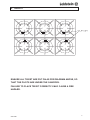
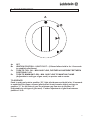
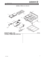
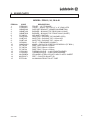
The Heavyweight BOILING TOP Series
PROUDLY AUSTRALIAN MADE
INSTALLATION PROCEDURE – USER MANUAL
SERVICE INSTRUCTION
MODELS PFB-12, PFB-24, PFB-36, PFB-48
WINER OF
AUSTRALIAN
DESIGN COUNCIL
AWARD 1990
PFB-24
GAS APPROVAL No.6250
ESTABLISHED 1911
The Cooking Equipment Professionals
www.goldsteineswood.com.au
TABLE OF CONTENTS
1.
INTRODUCTION
Page 3
2.
INSTALLATION
Page 4 & 5
3.
COMMISSIONING
Page 6
4.
MAINTENANCE
Page 7
5.
TRIVETS
Page 8
6.
PILOT OPERATION
Page 9
7.
PROBLEM SOLVING
Page 10
8.
DRAWINGS
Page 11
9.
SPARE PARTS
Page 12
10.
WARRANTY
Page 13
11.
BRANCHES
Page 14
2
IM038B1
1. INTRODUCTION
Congratulations for purchasing your Goldstein commercial cooking appliance.
J. Goldstein & Co. is a wholly owned Australian company and have been
operating since 1911, building high quality products. The information in this
manual will assist your installer and ensure correct location and connection.
Thoroughly read the user instructions and the user maintenance sections, as
understanding your products, its operation, and its cleaning and service
requirements will provide you with long and satisfactory service. Failure to do
so could shorten the life of the product and decrease its efficiency. Please ensure
only authorised service technicians are called to any difficulties that may arise.
INTRODUCTION
GOLDSTEIN HEAVYWEIGHT BOILING TOP SERIES
MODELS PFB-12, PFB-24, PFB-36, PFB-48
GOLDSTEIN Boiling Tops are designed to give long and satisfactory service and
incorporate the best possible materials and workmanship. Proper installation,
adjustment and preventative maintenance are vitally important if efficiency and
appearance are to be maintained.
Read these instructions carefully as they contain important safety information
regarding the installation, use and maintenance of the appliance.
RECEIVING INSPECTION
x Check crates for handling damage. After carefully uncrating, check for “concealed”
damage. Report any damage immediately to carrier and to dealer.
x Remove check all loose items from unit and check contents as found on back of
warranty cards.
x Check type and capacity of gas supply.
x The type of gas for which these Boiling Tops are factory adjusted can be seen on the
rating plate, located on the front panel of the Boiling Top.
IMPORTANT
A CLEANER THAT IS COMPATIBLE WITH ALUMINIUM MUST BE USED ON THE
EQUIPMENT OTHERWISE THE GAS PIPING WITHIN THE UNIT WILL BE DAMAGED
AND THIS WILL AUTOMATICALLY VOID THE WARRANTY.
“THE EQUIPMENT MUST BE INSTALLED BY A LICENSED GASFITTER AND
LICENSED CONTRACTOR”
3
IM038B1
2. INSTALLATION
RECEIVING INSPECTION – PRE-INSTALLATION
x Please follow these instructions carefully.
x
x
x
x
x
x
x
x
x
x
Remove cartons from unit and check for any damages.
Report any damages to the transport company or your dealer.
Set unit into correct position.
Adjust feet till they are touching the floor and using a spirit level, level from left to
right.
This operation is important as variation of 25mm to 76mm in a floor level is found to
be common.
Make sure unit is under an exhaust hood that provides adequate ventilation.
Check Rating plate to ensure appliance is suitable to the gas that it is being
connected to.
The Rating Plate is located on the front bottom left side and has what the unit is set
up for as factory set and tested.
Check all loose items listed on the back of the Warranty Card.
Note: The appliance must be installed by an Authorised person and in accordance
with the regulations of the local Gas Authority AS5601/AG601 and any other
authority having jurisdiction
The appliance has been tested and preset before leaving our Factory, but small
adjustments may be necessary to suit pressure supply.
Correct operation of the appliance must be tested as part of the installation
procedure.
1. Have a licensed gas fitter or your Gas Company connect the appliance to the
gas supply, Location of the connection is on the right side at rear. The fitting
is 19mm BSP. The appliance must be installed in accordance with the rules of
any authority having jurisdiction.
2. The pressure regulator (NG) and LPG standards (AS4563/AG300 1.1.05) are
supplied as a loose item and a hand stop tap must be supplied as close to the
appliance as possible to stop and pressure drop.
4
IM038B1
2. INSTALLATION
INSTALLATION
Please follow these instructions carefully
All equipment must be sitting level for proper operation and combustion where plinth
type installation is made, plinth height and front overhang must be 50 mm minimum.
Levelling can be made by the use of metal shims. For performer series where adjustable
legs are provided, levelling can be made easily due to the threaded construction of the
legs.
LIGHTING INSTRUCTIONS
Boiling Top arrangement:
A. All open burners may be ignited by the constant pilots.
B. Griddle top and hot top sections are provided with flame failure device gas
cocks Model 21S and is ignited by Piezo ignition.
ADJUSTMENT
Adjustments to burners and burner pilots can be made when necessary by any
qualified service organisation or your local gas utility service department.
NOTICE
PLEASE RETURN YOUR WARRANTY CARD
FAILURE TO DO SO WILL VOID WARRANTY
ON THE EQUIPMENT
5
IM038B1
3. COMMISSIONING
To be carried out be Gasfitter or Authority service person
COMMISSIONING APPLIANCE – DETAILS, TESTING, CHECKING PRESSURE ETC.
COMMISSIONING CHECK LIST
1.
CHECK FOR DAMAGE AND MISSING PARTS ON BACK OF WARRANTY
CARD.
2.
REMOVE ALL PLASTIC COATING FROM S/STEEL PANELS.
3.
MAKE SURE ALL PARTS ARE IN THEIR CORRECT POSITION E.G. TRAYS
BURNERS KNOBS.
4.
MAKE SURE ALL ELECTRIC AND GAS CONNECTIONS ARE CORRECT AND
TIGHT.
5.
TURN ON GAS OR ELECTRICITY
6.
ADJUST GAS PRESSURE WITH THREE-QUARTERS OF THE UNIT RUNNING,
ADJUST GAS PRESSURE.
NATURAL GAS
LPG
1.00 KPA
2.70 KPA
7.
TURN ON ONE AT A TIME TO MAKE SURE ALL IS WORKING E.G. BURNER,
RADIANT, GRIDDLE AND OVEN.
8.
SHOW CUSTOMER
A)
B)
C)
D)
9.
HOW TO WORK EQUIPMENT
HOW TO CLEAN
HOW TO PULL IT APART E.G. TRAY, TRIVETS
ALSO WHAT NOT TO DO, E.G. WATER WITH ELECTRICAL, GREASE
AND OIL IN CONTROLS.
CHECK TO MAKE SURE MANUALS AND WARRANTY CARDS ARE THERE.
ALSO GO THROUGH MANUAL WITH CUSTOMER E.G. LIGHTING,
CLEANING.
NOTE
WASH HOSES SHOULD NEVER BE USED ON THE APPLIANCE.
USE OF HOSES WILL VOID WARRANTY.
6
IM038B1
4. MAINTENANCE
MAINTENANCE PROCEDURE
USE PROTECTIVE CLOTHING FOR CLEANING TO AVOID DANGEROUS CONTACT
WITH HOT SURFACES.
1.
CAST IRON TRIVET
Wash in WARM soapy water, use Plastic Scourer if necessary. Dry with soft cloth
or paper towel.
2.
STAINLESS STEEL
Using a liquid cleaner indicated especially for this type metal can clean the
stainless steel finish. NEVER attempt to clean stainless steel with steel wool,
abrasive cloth or powders.
3.
PERIODIC CLEANING.
Keep grease, spillovers and other accumulations out of both top and oven burner
boxes or areas. The exterior painted surface of all appliances can be cleaned
with warm water and soap or a mild detergent. Removable drip or grease pans
are easily cleaned with warm water and soap or a mild detergent.
OPERATIONAL PROBLEMS AND SERVICE
No service is anticipated. However, should the occasion arise that service is required,
call a qualified gas service organisation or your local gas utility service department
DO NOT USE STEEL WOOL, ABRASIVE CLOTHS, CLEANSERS OR POWDERS!
If it is necessary to scrape stainless steel to remove encrusted materials, soak the
area with hot cloths to loosen the material, and then use a wood or nylon scraper.
DO NOT USE a metal knife, spatula, or any other metal tool to scrape stainless
Steel. Scratches are almost impossible to remove
7
IM038B1
5. TRIVETS
ENSURE ALL TRIVET ARE PUT ON AS PER DIAGRAM ABOVE, SO
THAT THE PILOTS ARE UNDER THE CANOPIES.
FAILURE TO PLACE TRIVET CORRECTLY MAY CAUSE A FIRE
HAZARD.
8
IM038B1
6. PILOT OPERATION
A
Q
B
XC
XD
A=
B=
C=
D=
OFF
IGNITION POSITION – LIGHT PILOT – (If flame failure hold in for 10 seconds
to establish pilot flame).
TURN TO FULL ON – MAX GAS FLOW, FURTHER ADJUSTMENT BETWEEN
POSITIONS C & D.
TURN TO MINIMUM FLOW – MIN. GAS FLOW TO MAINTAIN FLAME
(Adjustable to suit type of gas used.) as precise and accurate.
TO OPERATE:
Push in and turn knob to position “B”, light pilot burner and hold in for 10 seconds
to establish Pilot flame, release (pilot burner should remain alight) and turn to
position “C” for full flow of gas, for minimum gas flow turn to position “D”
(Adjustable to suit type of gas used). Further adjustment of gas flow between
position C & D.
9
IM038B1
7. PROBLEM SOLVING
1.
Burner goes out and flashes back
(a)
2.
3.
Cause
Excessive aeration.
Remedy
Adjust
Yellow Flame
(a)
Cause
Too much gas to burner.
Remedy
Check gas pressure and burner
Jet orifice.
(b)
Cause
Insufficient aeration.
Remedy
Adjust
Harsh noisy flame
(a)
Cause
Excessive aeration
Remedy
Adjust.
10
IM038B1
8. DRAWING
MODEL: PFB-12, 24, 36 & 48
2
1
2
10
1
4
6
7
13
5
9
8
14
15
3
12
11
11
IM038B1
9. SPARE PARTS
MODEL: PFB-12, 24, 36 & 48
ITEM No.
1.
2.
3.
4.
5.
6.
7.
8.
8..
9.
10.
11.
11.
11.
12.
12.
13.
14.
15.
CODE
GTR00002
GTR00003
GBNSP000
GBNBTL00
GBNBTS00
PF-00P33
GCKPF001
GIJBT235
GIJBT140
GPI00001
MKNPLM21
PF-12P24
PF-36P24
PF-32P24
GTC00450
GTC00600
MLESSBFA
MLEPLBF1
PFPTA001
DESCRIPTION
TRIVET – 12” PF RANGE
TRIVET – SOLID TOP FOR 12” x 12” (RAW) PFB
SUPPORT BRACKET (GBNBTL00/GBNBTS00)
BURNER – BOILING TOP REAR 26MJ (LONG)
BURNER – BOILING TOP FRONT 26MJ (SHORT)
AIR INLET CONTROL
GASCOCK – BOILING TOP BURNER (PFB)
INJECTOR – BOILING TOP 2.35mm N/G
INJECTOR – BOILING TOP 1.40mm L/P
PILOT – PFB BURNER (SINGLE)
KNOB – GASCOCK GCKPF001/GCKGR001 (PF BOIL.)
DRIP TRAY 241mm x 622mm
DRIP TRAY 830mm x 622mm
DRIP TRAY 737mm x 622mm
THERMOCOUPLE – L=450 FRONT BURNER
THERMOCOUPLE – L=600 REAR BURNER
STAINLESS STEEL LEG WITH ADJ PLASTIC INSERT
FEET – PLASTIC BULLET 2D
ALUMINIUM FRONT PILOT TUBE
12
IM038B1
10. WARRANTY
Installation must be carried out according to local regulations by qualified trade persons.
Isolating switch(es), shut-off valves etc must be within easy reach of the machine for
future service and maintenance requirements.
If in doubt call GOLDSTEIN/ESWOOD or their representative for further information. No
responsibility will be accepted for defects or damages by improper installation, for
changes to the product not authorised by GOLDSTEIN/ESWOOD or for operation
outside the technical specifications.
GOLDSTEIN/ESWOOD warrants their products to be free from defects in material and
workmanship under “normal use and service”. This does not include normal wear and
tear of parts. GOLDSTEIN/ESWOOD will repair or replace any parts, which in
GOLDSTEIN/ESWOOD’s sole judgement are defective in material or workmanship, in
accordance with the warranty offered.
This undertaking covers the provision of labour and parts for 12 months from the date of
delivery to the purchaser. This undertaking applies only to state capitals. Remote areas
are not covered by this commitment and special enquiries should be made. (Note:
Travel time not covered by warranty).
“To the maximum extent permitted by law, any liability on Goldstein/Eswood’s part or on
the part of its servants or agents for loss or damage of any kind whatsoever in
connection with the products, including liability for or in respect of any claim arising out of
contract, negligence or statute, shall not, in any event, exceed $100”
Labour under warranty is supplied free of charge during normal working hours, Monday
to Friday. Should warranty work be requested outside of our normal working hours a
labour charge will be applied equivalent to a normal hour rate, without out of hours
penalty rates. (Refer to last page of this manual for your closest branch for warranty
repair services).
13
IM038B1
11. GOLDSTEIN/ESWOOD BRANCHES
For inquiries please call your nearest state branch:
Head Office
211-213 Woodpark Road
Smithfield NSW 2164
Phone:
02 9604 7333
Fax:
02 9604 5420
Victoria
Unit 13
260-264 Wickham Road
Moorabbin
Victoria 3189
Phone:
03 9553 1488
Fax:
03 9553 0785
Queensland
Nautilus Complex
Unit 12
210 Queensport Road
Murarrie Qld 4172
Phone:
07 3890 1811
Fax:
07 3890 1788
South Australia
Suite 26
283-287 Sir Donald Bradman Drive
Brooklyn Park
South Australia 5032
Phone:
08 8238 3423
Fax:
08 8238 3400
Western Australia
Unit 1/10 Wittenberg Drive
Canning Vale
Western Australia 6155
Phone:
08 9456 0559
Fax:
08 9456 0554
14
IM038B1