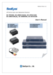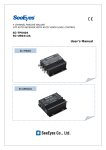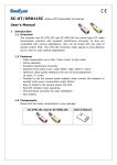
1
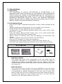
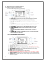
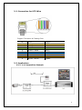
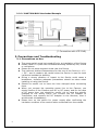
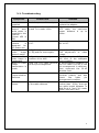
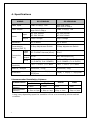
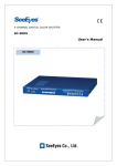
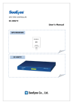
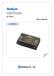
TWISTED PAIR VIDEO TRANSMISSION SC-UT0124M SC-UR0124M User's Manual SC-UT0124M SC-UR0124M Precaution and Safety Guidelines Please read this user’s manual thoroughly prior to use the unit for its easy and convenient use. Should you have any part of them not understandable or if you have any problem during your installation or in using it, please contact us. Reproduction of this instruction or any part thereof without permission is strictly prohibited. You must read the precautions required for safe operation prior to using it and operate it correctly. Please understand that the contents of this operating instruction may differ slightly due to functional improvement of a product and based on the specification chosen by the user. You can use this product easier and more conveniently if you use the function of the product only after reading this operating instruction carefully. CAUTION RISK OF ELECTRIC SHOCK DO NOT OPEN CAUTION : TO REDUCE THE RISK OF ELECTRIC SHOCK, DO NOT REMOVE COVER. NO USER SERVICEABLE PARTS INSIDE. REFER SERVICING TO QUALIFIED SERVICE PERSONNEL. The lightning flash with arrowhead symbol within an equilateral triangle, is intended to alert the user to the presence of uninsulated “dangerous voltage” within the product‟s enclosure that may be of sufficient magnitude to constitute a risk of electric shock to persons. The exclamation point within an equilateral triangle is intended to alert the user to the presence of important operating and maintenance (servicing) instructions in the literature accompanying the product. WARNING: To reduce the risk of fire or electric shock, do not expose this apparatus to rain or moisture. CE mark under EMC and low voltage Directives for the European Union. 1 1. Introduction 1.1. Summary UTP transmitter & receiver (SC-UT0124M & SC-UR0124M) is an equipment that is able to perform the long distance video transmission without having an impact of interference due to the transmission is made utilizing Twisted Pair Cable (UTP, FTP, STP) by converting the Unbalanced Differential Signal by nature into Balanced Differential Signal, and also able to transmit camera driving power and its control data by using the surplus insulated conductors. 1.2. Product features • • • • • • • • • • With one UTP cable 1 balanced transmission of video, power and data can be made. Various interferences induced to the line are reduced to the minimum. A BNC harness has been applied for user‟s convenience. Provided with a 2-step distance adjusting switch (Low: within 600m, High: within 600 ~ 2.4km) Using UTP cables; Maximum B/W: 2.4km, Color: up to 1.8km leveled video signals can be transmitted when applied „high‟. Able to select an optimum level video by adjusting A.Level/F.Level gain control. Able for a multiple use of AC 24V 300mA / DC 12V 500mA. Using a RJ-45 connector, it allows easy connection. Compatible with CVBS output camera / CVBS input DVR, Monitor, etc. Small and light weighted allowing installation done inside camera housing. SC-UT/R0124M User’s Manual Power Adapter ※ Unbalanced Signal This means the signal which magnitudes of the two metal lines are transmitted differently on a transmission line on which the signal is transmitted by making combination of the two lines. Namely, this is the method of use that one of the metal lines is used as a GND and the other as a signal line. ※ Balanced Signal This means the signal of which the same magnitude of the two metal conductive lines is transmitted on a transmission line on which the signal is transmitted by making combination of the two lines. In short, this doesn‟t mean that one of the conductive lines becomes a GND but both of the lines send signals as a sine waveform but this is the case that the waveforms are 180 degree different each other. 2 2. Appearance and Connection 2.1. Name of Part and Functions 2.1.1.SC-UT0124M, Active Transmitter ① VIDEO IN: Connect with the video output terminal of Camera. ② CAM POWER: Driving power output terminal of Camera. For a Camera using separate power, it should not be connected. ③ RS-485: RS-485 DATA connection terminal. To be careful with Polarity ④ POWER IN: Used when a separate Adapter needs to be connected. / If power is supplied from Junction Box, it should not be connected. ⑤ UTP CABLE: Connect an UTP Cable attached with RJ-45 Plug. ⑥ CABLE LENGTH: Adjust the H/L according to the UTP Cable distance. Maximum transmission distance L: 600m or less / H: 600m ~ 2.4km. ⑦ POWER LED: If power is supplied to the SC-UT0124M, the Power LED is turned on in red color. 2-1-2. SC-UR0124M, Active Receiver ① POWER IN: Adaptor connection terminal. ② RS-485: RS-485 DATA connection terminal. Be careful with polarity. ③ POWER LED: If power is supplied to the SC-UR0124M, the Power LED is turned on in red. ④ UTP CABLE: Connect the UTP Cable attached with a RJ-45 Plug. ⑤ AMP: Adjust video image level. ⑥ F.EQ: Make a fine adjustment for video image. Maximum transmission distance L: 600m or less / H: 600m ~ 2.4km. ⑦ CABLE LENGTH: Adjust the L/H according to the UTP Cable distance. ⑧ VIDEO OUT: Connect with the video image input terminal of DVR, Monitor or Quads. 3 2-2. Connection for UTP Wire Copper Connector & Coating Color No. 1 2 3 4 5 6 7 8 Color Orange Orange + White Green Green + White Blue Blue + White Brown Brown + White Function VIDEO + VIDEO DATA + DATA POWER + POWER + POWER POWER - 2-3. Application 2-3-1. 1:1 Composition Example 4 2-3-2. JUNCTION BOX Interlocked Example (* Connection with UTP DVR) 3. Precautions and Troubleshooting 3-1. Precautions on Use 5 The power switch must be turned off prior to installation of the Device. Please install in a place well-ventilated avoiding extremely hot, humid or cold places. Please do not place magnetic kinds near the Device. The optimum ambient temperature for the use of the Device is -10℃ ~ 50℃, and it needs to be careful when the Device is used for both inside and outside the building. Giving a strong vibration or impact to the Device could cause a breakdown, therefore adequate precautions should be taken when installing or using the Device. Should be careful not to have the lines changed when connecting them. When you connect the operating power line to the Camera, you should confirm if the Camera uses AC or DC power, and for the case of DC power then you should be careful not to have the polarity changed to the wrong one(If you connect the AC Adapter to Transmitter, and connect the DC Adapter to the Receiver, then it would cause a breakdown). Please turn on the switch for power supply after confirming the insulation condition of the control cable connected from the outside. 3-2. Troubleshooting Symptoms Power is not supplied. The camera doesn‟t work while power is supplied to the receiver (Power LED is ON). When the camera is designed for DC power use. The color of video image doesn‟t match. The level of the video image is inadequate. When no video image transmission is made. Check Point Solution Check the power of the adapter. If it still doesn‟t work, then replace the adapter. Check if the distance between Due to the characteristic of Rx and Tx is under 100m. UTP cable, the maximum power distance is up to 100m. Check if the input power is AC Convert the input power for or DC. Rx. to DC. Verify the adjustment condition Adjust the F.EQ and make a of F.EQ and the check again. fine adjustment to video image. Verify the fine adjustment By adjusting the AMP, place condition of the AMP. the level to the adequate level condition. Check the UTP cable terminal If the connection condition of and the pin arrangement. the UTP cable is RJ-45 or the pin arrangement is deficient, then reconnect the RJ-45 Modular Jack. 485 Check the RS-485 data cable. Check the RS-485 data Communication terminal polarity and also Deficient check the cable pin arrangement condition. The screen is Adjust the cable length based If the cable distance is frozen. on the cable distance. further than 600m, then set the cable length between Tx and Rx at H, and if it‟s under 600m, then set it at L. 6 4. Specifications MODEL SC-UT0124M SC-UR0124M Video Input CVBS 1.0Vp-p, 75Ω Low 51Ω 1Vp-p, High 51Ω 2.5Vp-p Video Output Low 51Ω 1Vp-p High 51Ω 2.5Vp-p CVBS 1.0Vp-p, 75Ω Input DC 12V 500mA AC 24V 300mA DC 12V 500mA AC 24V 300mA Output Loop Through Loop Through DC to 8MHz DC to 8MHz 2 Step Adjustment Switch 2 Step Adjustment Switch DC-F & BNC Harness(45cm) RJ-45 RJ-45 BNC Harness(45cm) DATA: 4P Terminal Block (1~2:DATA/ 3~4: POWER) DATA: 4P Terminal Block (1~2: POWER / 3~4: DATA) Temperature /Humidity -10℃ ~ +50℃ / 0 ~ 80% -10℃ ~ +50℃ / 0 ~ 80% Material / Weight Aluminum / 120g Aluminum/ 120g Dimension 75(W) ⅹ 25(D)mm Power Bandwidth Maximum Transmission Distance (CAT 5) Video Input Connection Video Port Output DATA 60(H) ⅹ 75(W) ⅹ 60(H) ⅹ 25(D)mm * Recommended Installation Distance Video Image Classification Power Data Color B/W Maximum 1.8km 2.4km 100m 1.2km Distance Recommended 1.2km or less 1.8km or less 100m or less 1.2km or less Distance The above are the recommended installation distance for normal operation, but it may vary depending upon the condition of line or surrounding environmental condition. 7 5. Warranty Certificate This product has passed thorough quality control and test, and if this gets broken during normal use, we provide 12 months warranty service. Model No. Serial No. Distributor Date you purchased Place you purchased Warranty Period Name Purchaser Address One (1) year from the date of purchase • Please • Please check this warranty indication first. contact your distributor after checking out any defect in the products. • The standard for repairing, replacement or reimbursement follows Customer. • Warranty content any defect under normal use within the warranty service period we give you free repair service according to the warranty certificate. • We charge you with the fee of parts and service despite of free warranty service period. Any breakage made without care such as: - Breakage or trouble made by natural disaster. - Breakage or trouble made by breaking the product guide or manual. - Breakage or trouble made by wrong power voltage or frequency. - When you want to reassemble for full system or replace parts within warranty service period. - When unauthorized person modified or made damage on the product trying to repair it. • Please note that we don‟t support the breakage after warranty service period is expired. If the customer wants to get it repaired, we charge them with the fee. • The specification is subject to change without prior notice for quality improvement. 8 [MEMO] 9 [MEMO] 10 SeeEyes Co.,Ltd is the New Corporate Name of Samsung CCTV Service Co.,Ltd SeeEyes Co.,Ltd #502~506, Sunil Technopia, 440, Sangdaewon-Dong, Jungwon-Gu, Sungnam-Si, Gyeonggi-Do, Korea TEL : +82-(0)31-777-3508 FAX : +82-(0)31-777-3512 EMAIL : [email protected] http://www.sscctv.com/eng 11