1
USB-2000 Series
USB 2.0 Full-Speed High Performance DAQ module
User's Manual
Revision History / Overview
Revision History
Revision
Date
Description of Change
1. Adding USB-2045 Module Information
2. Adding USB-2051 Module Information
1.09
May 8, 2014
3. Adding USB-2055 Module Information
4. Adding USB-2060 Module Information
5. Adding DI API
1.08
Jan 29, 2013
6. Adding System API – SetAutoResetWDT
1.07
Sep 20, 2012
7. Adding DO API – DO_WriteValue
1.06
Jul 6,2012
1.05
Jun 21, 2012
1. Modifying analog output type code
1.04
Apr 23, 2012
1. Changing the color of LED indicators
1. Adding DO API
2. Adding information for USB-2064
1. Adding information for USB-2084
1.03
Dec 29, 2011
2. Adding PI API
3. Adding PI related error codes
1.02
Dec 20, 2011
Adding ERR_USBDEV_ERROR_WRITEFILE error code
1.01
Dec 15, 2011
Modify specification of USB-2019
1.00
Oct 31, 2011
First revision released
i
Document version: 1.09
Preface / Overview
Preface
Warranty
All products manufactured by ICP DAS are under warranty regarding defective
materials for a period of one year from the date of delivery to the original purchaser.
Warning
ICP DAS assumes no liability for damages resulting from the use of this product. ICP
DAS reserves the right to change this manual at any time without notice. The information
furnished by ICP DAS is believed to be accurate and reliable. However, no responsibility
is assumed by ICP DAS for its use, or for any infringements of patents or other rights of
third parties resulting from its use.
Copyright
Copyright © 2011 by ICP DAS CO., LTD. All rights are reserved.
Trademark
The names used for identification only may be registered trademarks of their
respective companies.
ii
Document version: 1.09
Content / Overview
Content
Revision History .................................................................................................................................. i
Preface...................................................................................................................................................ii
Content ............................................................................................................................................... iii
1 Introduction.................................................................................................................................... 1
1.1 Overview .............................................................................................................................. 1
1.2 Feature ................................................................................................................................. 1
1.3 Applications ....................................................................................................................... 2
1.4 Specifications..................................................................................................................... 2
1.4.1 General ..................................................................................................................... 2
1.4.2 USB-2019 ................................................................................................................ 3
1.4.3 USB-2045 ................................................................................................................ 4
1.4.4 USB-2051 ................................................................................................................ 5
1.4.5 USB-2055 ................................................................................................................ 6
1.4.6 USB-2060 ................................................................................................................ 8
1.4.7 USB-2064 .............................................................................................................. 10
1.4.8 USB-2084 .............................................................................................................. 11
1.5 Product Check List ......................................................................................................... 12
2 Hardware Information .............................................................................................................. 13
2.1 Module Overview ........................................................................................................... 13
2.1.1 USB-2019 .............................................................................................................. 14
2.1.2 USB-2045 & USB-2051 & USB-2055 &USB-2060 ................................ 15
2.1.3 USB-2064 .............................................................................................................. 15
2.1.4 USB-2084 .............................................................................................................. 16
2.1.5 CA-USB15 ............................................................................................................. 16
2.2 Connector Pin Assignment ........................................................................................ 17
2.2.1 USB-2019 .............................................................................................................. 17
2.2.2 USB-2045 .............................................................................................................. 17
2.2.3 USB-2051 .............................................................................................................. 18
2.2.4 USB-2055 .............................................................................................................. 18
2.2.5 USB-2060 .............................................................................................................. 19
2.2.6 USB-2064 .............................................................................................................. 19
2.2.7 USB-2084 .............................................................................................................. 20
2.3 Wiring ................................................................................................................................. 21
2.3.1 USB-2019 .............................................................................................................. 21
iii
Document version: 1.09
Content / Overview
2.3.2 USB-2045 .............................................................................................................. 21
2.3.3 USB-2051 .............................................................................................................. 21
2.3.4 USB-2055 .............................................................................................................. 22
2.3.5 USB-2060 .............................................................................................................. 23
2.3.6 USB-2064 .............................................................................................................. 23
2.3.7 USB-2084 .............................................................................................................. 24
2.4 Hardware Configuration ............................................................................................. 25
2.4.1 Board ID ................................................................................................................. 25
2.4.2 Firmware Update ............................................................................................... 25
2.4.3 USB-2019 .............................................................................................................. 26
2.4.4 USB-2045 .............................................................................................................. 26
2.4.5 USB-2051 .............................................................................................................. 27
2.4.6 USB-2055 .............................................................................................................. 27
2.4.7 USB-2060 .............................................................................................................. 27
2.4.8 USB-2064 .............................................................................................................. 28
2.4.9 USB-2084 .............................................................................................................. 29
2.5 LED Indicators.................................................................................................................. 30
2.5.1 Normal Operation ............................................................................................. 30
2.5.2 Firmware update ................................................................................................ 30
3 Installation..................................................................................................................................... 31
3.1 Hardware ........................................................................................................................... 31
3.1.1 Connecting to ICP DAS USB series I/O module ..................................... 31
3.2 Software ............................................................................................................................. 31
3.2.1 Utility....................................................................................................................... 32
3.2.2 ICP DAS USB I/O Software Integration...................................................... 42
3.2.3 Samples ................................................................................................................. 44
4 Operation ...................................................................................................................................... 45
4.1 Hardware structure........................................................................................................ 45
4.2 Software structure ......................................................................................................... 45
5 ICP DAS USB Class Members ................................................................................................. 48
5.1 Table of Constructors ................................................................................................... 48
5.2 Table of Static Methods .............................................................................................. 48
5.3 Table of Public Methods ............................................................................................. 48
5.3.1 System .................................................................................................................... 48
5.3.2 Device ..................................................................................................................... 49
5.3.3 Digital Input ......................................................................................................... 49
iv
Document version: 1.09
Content / Overview
5.3.4 Digital Output ..................................................................................................... 50
5.3.5 Analog Input ........................................................................................................ 50
5.3.6 Pulse Input ............................................................................................................ 51
5.3.7 Other ....................................................................................................................... 52
5.4 Constructors..................................................................................................................... 52
5.4.1 ICPDAS_USBIO .................................................................................................... 52
5.5 Static Methods ................................................................................................................ 53
5.5.1 ListDevice .............................................................................................................. 53
5.5.2 ScanDevice ........................................................................................................... 54
5.6 Public Methods ............................................................................................................... 55
5.6.1 System .................................................................................................................... 55
5.6.2 Device ..................................................................................................................... 61
5.6.3 Digital Input ......................................................................................................... 82
5.6.4 Digital Output ..................................................................................................... 97
5.6.5 Analog Input ..................................................................................................... 119
5.6.6 Pulse Input ......................................................................................................... 157
6 Troubleshooting ...................................................................................................................... 199
Appendix A .................................................................................................................................... 200
A.1 Analog Input Type Code .......................................................................................... 200
A.2 Analog Output Type Code ...................................................................................... 201
A.3 Pulse Input Type Code.............................................................................................. 201
A.4 Channel Status ............................................................................................................. 201
Appendix B .................................................................................................................................... 202
B.1 Error Codes .................................................................................................................... 202
v
Document version: 1.09
Introduction / Overview
1
Introduction
1.1 Overview
The ICP DAS USB series I/O modules are highly flexible solution for data acquisition.
It provides easy USB plug-and-play operation and equips accurate measurement for all
kinds of applications of automations. Compared with the traditional PC-based cards like
PCI, PC/104 and ISA cards, users can achieve data acquisition easier and quicker via ICP
DAS USB series I/O modules. Besides, through ICP DAS USB I/O utility, users can
configure and test modules directly and easily without any coding. The friendly API
library is also provided for users to develop own USB application.
1.2 Feature
Maximum 10KS/s sampling rate
Wide operating temperature range
RoHS compliant
USB 2.0 Full-Speed compliant
No external power supply (Powered by USB)
Plug-and-Play without driver installation
Lockable USB cable
Support firmware update via USB
Utility tool for module configuration and I/O testing easily and quickly
PWR/RUN/ERR LED indicator
Built-in dual watchdog (hardware/software)
Providing API Library (VC/VB/BCB/.NET)
Module supported for Win2000/XP and Win7 (32/64 bit)
1
Document version: 1.09
Introduction / Applications
1.3 Applications
Building automation
Factory automation
Machine automation
Data acquisition and control
Environment monitor
Laboratory equipment and research
1.4 Specifications
1.4.1 General
Communication
Interface
Watchdog
USB 2.0 Full-Speed
1 Hardware watchdog ( 1.6 second )
1 Software watchdog ( Programmable )
LED Indicators / Display
System LED Indicators
3 LED as Power, Run and Error
I/O LED Indicators
1 LED / channel as I/O status for Digital and Pulse I/O
EMC
ESD ( IEC 61000-4-2 )
EFT (IEC 61000-4-4)
4 kV contact for each terminal
8 kV air for random point
0.5kV for USB cable
0.5kV for I/O terminal
Environment
Operating Temperature Range
-25 ~ +75℃
Storage Temperature Range
-40 ~ +85℃
Humidity
10 ~ 95% RH, non-condensing
2
Document version: 1.09
Introduction / Specifications
1.4.2 USB-2019
The USB-2019 is an 8-channel universal analog input
module. It supports the over-voltage protection of up to
240Vrms. In addition, it has voltage and current input types. It
also widely supports thermocouple devices with J, K, T, E, R, S, B,
N, C, L, M and LDIN43710 types. Moreover, it provides extremely
accurate
thermocouple
measurement
and
automatically
cold-junction compensation for each channel. Finally, it features
open wire detection for thermocouple and 4 ~ 20 mA inputs for
each channel.
Analog Input
Channels
8 differential
Voltage
Input Type
Current
Thermocouple
±15 mV, ±50 mV, ±100 mV, ±150 mV,
±500 mV, ±1 V, ±2.5 V, ±5 V, ±10 V
±20 mA, 0 ~ +20 mA, +4 ~ +20 mA
( Note : An external resistor is required )
J, K, T, E, R, S, B, N, C, L, M and LDIN43710
Resolution
16 bit
Accuracy
±0.1% FSR
Sampling Rate
10 Hz ( Total )
Zero Drift
±20 μV/℃
Span Drift
±25 ppm/℃
Common Mode Rejection
86 dB
Normal Mode Rejection
100 dB
Input Impedance
Voltage
> 400 kΩ
Current
125Ω (External resistor is required)
Intra-Module Isolation,
Field-to-Logic
3000 VDC
Overvoltage protection
240 Vrms
Individual Channel Configuration
Yes
Open Wire Detection
Yes (Software programmable)
Power
Power Consumption
1.45W maximum
Mechanical
Dimensions ( W×L×H )
33mm × 119mm × 107mm
3
Document version: 1.09
Introduction / Specifications
1.4.3 USB-2045
The USB-2045 is a full-speed USB device with 16 digital
output channels module. The USB-2045 supports source type
output and equips with short circuit protection. There are 16
LED indicators that can be used to monitor the status of the
digital output channels. The 4 kV ESD protection, 4 kV EFT
protection, 3 kV surge protection for power input and 3750
VDC Intra-module isolation are standard.
Digital Output
Channels
16
Type
Open Collector, Sink (NPN)
Load Voltage
+3.5~+50VDC
Max. Load Current
650 mA/Channel
Overvoltage Protection
60 VDC
Overload Protection
1.4A (with short-circuit protection)
Power-on Value
Yes
Safe Value
Yes
Power
Power Consumption
1.0 W max.
Mechanical
Dimensions ( W×L×H )
72 mm x 123 mm x 35 mm
4
Document version: 1.09
Introduction / Specifications
1.4.4 USB-2051
The USB-2051 is a full-speed USB device with 16 digital
input channels module. The USB-2051 offers 16 channels for
digital input, catering for both dry and wet contact, with an
effective distance for dry contact of up to 500 meters. All
channels not only feature photocouple isolation, but can also
be used as 16-bit counters. The USB-2051 has 16 LED
indicators that can be used to monitor the status of the digital
input channels. 4 kV ESD protection and 3750 VDC
intra-module isolation are standard.
Digital Input
Channels
16
Dry Contact
Source
Wet Contact
Sink/Source
On Voltage
Dry Contact
Close to GND
Level
Wet Contact
+10 VDC ~ +50 VDC
Off Voltage
Dry Contact
Open
Level
Wet Contact
+4 VDC Max.
Type
Effective Distance For Dry Contact
500 meters Max.
Input Impedance
10 KΩ
Overvoltage Protection
70 VDC
Max. Count
Max. Input
Counter
Frequency
Min. Pulse
Width
65535 (16-bit)
500 Hz
1 ms
Power
Power Consumption
1.03 W max.
Mechanical
Dimensions ( W×L×H )
72 mm x 123 mm x 35 mm
5
Document version: 1.09
Introduction / Specifications
1.4.5 USB-2055
The USB-2055 is a full-speed USB device with 8 digital
input and digital output channels module. The USB-2055
offers 8 isolated channels for digital input and 8 isolated
channels for digital output. Either sink-type or source-type
digital input can be selected via wire connections. All digital
input channels are also able to be used as 16-bit counters.
The USB-2055 supports source-type output with short circuit
protection. There are options to enable both power-on and
safety values. The USB-2055 has 16 LED indicators that can be
used to monitor the status of the digital input and digital
output channels. 4 kV ESD protection and 3750 VDC
intra-module isolation are standard.
Digital Input
Channels
8
Dry Contact
Source
Wet Contact
Sink/Source
On Voltage
Dry Contact
Close to GND
Level
Wet Contact
+10 VDC ~ +50 VDC
Off Voltage
Dry Contact
Open
Level
Wet Contact
+4 VDC Max.
Type
Effective Distance For Dry Contact
500 meters Max.
Input Impedance
10 KΩ
Overvoltage Protection
70 VDC
Max. Count
Max. Input
Counter
Frequency
Min. Pulse
Width
65535 (16-bit)
500 Hz
1 ms
Digital Output
Channels
8
Type
Open Collector, Sink (NPN)
Load Voltage
+3.5~+50VDC
Max. Load Current
650 mA/Channel
Overvoltage Protection
60 VDC
Overload Protection
1.4A (with short-circuit protection)
6
Document version: 1.09
Introduction / Specifications
Power-on Value
Yes
Safe Value
Yes
Power
Power Consumption
1.2 W max.
Mechanical
Dimensions ( W×L×H )
33mm × 87mm × 107mm
7
Document version: 1.09
Introduction / Specifications
1.4.6 USB-2060
The USB-2060 is a full-speed USB device with 8 digital
input and digital output channels module. The USB-2060
provides 6 digital input channels, 6 Form A signal relay output
channels. All digital input channels can be used as 16-bit
counters. In addition, the digital input channels can be
selected either as sink or source type via wire connections.
The USB-2060 also provides 12 LED indicators that can be
used to monitor the status of the digital input and relay
output. There are also options for configuring power-on and
safe values. 4 kV ESD protection and 3750 VDC intra-module
isolation are also provided to enhance noise protection
capabilities in industrial environments.
Digital Input
Channels
6
Dry Contact
Source
Wet Contact
Sink/Source
On Voltage
Dry Contact
Close to GND
Level
Wet Contact
+10 VDC ~ +50 VDC
Off Voltage
Dry Contact
Open
Level
Wet Contact
+4 VDC Max.
Type
Effective Distance For Dry Contact
500 meters Max.
Input Impedance
10 KΩ
Overvoltage Protection
70 VDC
Max. Count
Max. Input
Counter
Frequency
Min. Pulse
Width
65535 (16-bit)
500 Hz
1 ms
Relay Output
Channels
6
Output Type
Form A (SPST-NO)
Contact Rating
DC
5A 30VDC
(Resistive Load)
AC
5A 250VAC (47~63Hz)
Operate Time
10ms max.
Release Time
5ms max.
8
Document version: 1.09
Introduction / Specifications
Insulation Resistance
Between Open
Dielectric
Contact
Strength
Between Coil and
Contact
Endurance
1,000 MΩ at 500VDC
1000VAC (1 min.)
3000VAC (1 min.)
7
Mechanical
2 x 10 ops
Electrical
1 x 10 ops
5
Power-on Value
Yes
Safe Value
Yes
Power
Power Consumption
1.3 W max.
Mechanical
Dimensions ( W×L×H )
33mm × 87mm × 107mm
9
Document version: 1.09
Introduction / Specifications
1.4.7 USB-2064
The USB-2064 is an 8-channel power relay output
module with the USB interface. It provides a maximum 5A
driving load current for variety applications. In addition, This
module also provides the safety functionality to secure
devices in the field. Besides, it also supports power-on
configuration to customize initial state.
Relay Output
Channels
8
Output Type
Form A (SPST-NO)
Contact Rating (Resistive Load)
5A 250VAC (47~63Hz)
5A 30VDC
Operate Time
10ms max.
Release Time
5ms max.
Insulation Resistance
1,000 MΩ at 500VDC
Dielectric Strength
Endurance
Power Consumption
Between Open Contact
1000VAC (1 min.)
Between Coil and Contact
3000VAC (1 min.)
Mechanical
20,000,000 times min.
Electrical
100,000 times min.
1.235W max.
Mechanical
Dimensions ( W×L×H )
33mm × 87mm × 107mm
10
Document version: 1.09
Introduction / Specifications
1.4.8 USB-2084
The USB-2084 is an 8-channel counters module with the
USB interface. It provides a variety of measurement applications,
such as measuring a number of time-related quantities, counting
events or totalizing, and monitoring position with quadrature
encoders. In addition, a digital filter is used to eliminate the
effects of noise, and the filter’s parameters are adjustable by
software.
Counter
4 channel counter type Up/Down
Channels
4 channel counter type Dir/Pulse
4 channel counter type A/B Phase
8 channels for counter type Up and Frequency
Input Type
Up, Frequency, Up/Down, Dir/Pulse, A/B Phase
Resolution
32 bit
Input Frequency
500kHz maximum
Digital Noise Filter
1~32767uS (Software programmable)
Frequency Accuracy
±0.4%
Isolated Input Level
Non-isolated Input Level
Intra-Module Isolation,
Field-to-Logic
On Voltage Level
+4.5VDC~+30VDC
Off Voltage Level
+1VDC maximum
On Voltage Level
+2VDC~+5VDC
Off Voltage Level
0VDC~+0.8VDC
2500 VDC
Individual Channel Configuration
Yes
Power Consumption
1.11W maximum
Mechanical
Dimensions ( W×L×H )
33mm × 102mm × 107mm
11
Document version: 1.09
Introduction / Product Check List
1.5 Product Check List
The package includes the following items:
One ICP DAS USB I/O module
One Quick Start Guide
One USB cable with lockable kit (CA-USB15)
It is highly recommended to read the Quick Start Guide first before using ICP DAS
USB I/O modules. There is some useful information in the Quick Start Guide:
How to install hardware and use utility
12
Document version: 1.09
Hardware Information / Module Overview
2
Hardware Information
2.1 Module Overview
LEDs & I/Os Terminal
Frame Ground
Board ID Rotary Switch
DIN Rail Mount
USB Type B connector
Normal / Firmware
update Mode Switch
DIN Rail Lock
Board ID Rotary Switch
0
: User defined (Software Programmable)
1 ~ 15
: Fix board ID
Normal / Firmware Update Mode Switch
INIT
: Firmware update mode
RUN
: Normal mode
13
Document version: 1.09
Hardware Information / Module Overview
2.1.1 USB-2019
2.1.1.1 Body
2.1.1.2 CN-1824
The CN-1824 is a connector transfers DB-25 connector to 18-pin terminal block to
help user to wire. The dimension is shown as follow.
14
Document version: 1.09
Hardware Information / Module Overview
2.1.2 USB-2045 & USB-2051 & USB-2055 &USB-2060
2.1.3 USB-2064
Figure 2-1, Figure 2-2 The USB-2084 left and front side view
15
Document version: 1.09
Hardware Information / Module Overview
2.1.4 USB-2084
Figure 2-3, Figure 2-4 The USB-2084 left and front side view
2.1.5 CA-USB15
16
Document version: 1.09
Hardware Information / Connector Pin Assignment
2.2 Connector Pin Assignment
2.2.1 USB-2019
Signal
Description
AGND
Analog input ground
CH(N)+
Analog input channel N positive reference.
CH(N)-
Analog input channel N negative reference.
2.2.2 USB-2045
Signal
Description
DO(N)
The Digital Output for Channel N
Ext.PWR
The Power Source Input Pin
Ext.GND
The Ground of Power Source Input Pin
17
Document version: 1.09
Hardware Information / Connector Pin Assignment
2.2.3 USB-2051
Signal
Description
DI(N)
The Digital Input for Channel N
DI.GND
The Ground of Current Path of Dry Contact
DI.COM
The Common Pin for Wet Contact
2.2.4 USB-2055
Signal
Description
DI(N)
The Digital Input for Channel N
DI.GND
The Ground of Current Path of Dry Contact
DI.COM
The Common Pin for Wet Contact
DO(N)
The Digital Output for Channel N
Ext.PWR
The Power Source Input Pin
Ext.GND
The Ground of Power Source Input Pin
18
Document version: 1.09
Hardware Information / Connector Pin Assignment
2.2.5 USB-2060
Signal
Description
DI(N)
The Digital Input for Channel N
DI.GND
The Ground of Current Path of Dry Contact
DI.COM
The Common Pin for Wet Contact
RL(N) NO
The NO pin of relay(N)
RL(N) COM
The COM pin of relay(N)
2.2.6 USB-2064
Signal
Description
RL(N) NO
The NO pin of relay(N)
RL(N) COM
The COM pin of relay(N)
19
Document version: 1.09
Hardware Information / Connector Pin Assignment
2.2.7 USB-2084
Signal
Description
GND
Ground pin for non-isolated connection
C(N)A+
Counter positive signal channel for pair A
C(N)A-
Counter negative signal channel for pair A
C(N)B+
Counter positive signal channel for pair B
C(N)B-
Counter negative signal channel for pair B
N.C
No connection on this pin
20
Document version: 1.09
Hardware Information / Wiring
2.3 Wiring
2.3.1 USB-2019
Voltage Input
Thermocouple Input
Current Input
Note: When connecting to current source, an
external 125Ω resistor is required.
2.3.2 USB-2045
Output
ON
OFF
ON
OFF
Drive Relay
Resistance
Load
2.3.3 USB-2051
Input
Relay Contact
(Dry)
Open
Collector (Dry)
21
Document version: 1.09
Hardware Information / Wiring
Relay Contact
(Wet)
NPN Output
(Wet)
2.3.4 USB-2055
Digital Input
Input
ON
OFF
ON
OFF
Relay Contact
(Dry)
Open
Collector (Dry)
Relay Contact
(Wet)
NPN Output
(Wet)
Digital Output
Output
Drive Relay
Resistance
Load
22
Document version: 1.09
Hardware Information / Wiring
2.3.5 USB-2060
Digital Input
Input
ON
OFF
ON State LED ON
OFF State LED OFF
Readback as 1
Readback as 0
ON State LED ON
OFF State LED OFF
Readback as 1
Readback as 0
Relay Contact
(Dry)
Open
Collector (Dry)
Relay Contact
(Wet)
NPN Output
(Wet)
Relay Output
Output Type
Relay
Contact
2.3.6 USB-2064
Output Type
Relay
Contact
23
Document version: 1.09
Hardware Information / Wiring
2.3.7 USB-2084
Input Mode
Isolated
Non-isolated
Dir/Pulse
Up/Down
Up
A/B Phase
(Quadrant)
Frequency
24
Document version: 1.09
Hardware Information / Hardware Configuration
2.4 Hardware Configuration
The ICP DAS USB series I/O modules provide two basic configurations of hardware
to configure board ID and enable firmware update functionality.
2.4.1 Board ID
The board ID is used to identify two modules with same product number connected
to computer. When two more modules with same product number are connected, each
of them must be set to different board ID to prevent conflict and unexpected errors. The
board ID can be configured by the rotary switch. The location of the rotary switch is
shown in figure 2-15. The value of board ID can be configured from 1 ~ 15 by hardware,
and can be configured from 16 ~ 127 by software when switched to 0.
Figure 2-5 The hardware setting for board ID
2.4.2 Firmware Update
The ICP DAS USB series I/O modules provide firmware updateable functionality.
Users can update firmware if latest firmware released. The switch setting is shown in
figure 2-16. The INIT side of the switch means firmware update mode, run side means
normal operation.
25
Document version: 1.09
Hardware Information / Hardware Configuration
Figure 2-6 The hardware setting for enabling firmware update functionality
2.4.3 USB-2019
2.4.3.1 Hardware Watchdog
The USB-2019 has a build-in hardware watchdog. It is recommended to enable this
functionality. The hardware watchdog can be set by jumper JP1. The watchdog setting is
enabled by default.
Jumper
JP1
Setting
Enable
Disable
(Default)
2.4.4 USB-2045
2.4.4.1 Hardware Watchdog
The USB-2045 has a build-in hardware watchdog. It is recommended to enable this
functionality. The hardware watchdog can be set by jumper JP1. The watchdog setting is
enabled by default.
Jumper
JP1
Setting
Enable
Disable
(Default)
26
Document version: 1.09
Hardware Information / Hardware Configuration
2.4.5 USB-2051
2.4.5.1 Hardware Watchdog
The USB-2051 has a build-in hardware watchdog. It is recommended to enable this
functionality. The hardware watchdog can be set by jumper JP1. The watchdog setting is
enabled by default.
Jumper
JP1
Setting
Enable
Disable
(Default)
2.4.6 USB-2055
2.4.6.1 Hardware Watchdog
The USB-2055 has a build-in hardware watchdog. It is recommended to enable this
functionality. The hardware watchdog can be set by jumper JP1. The watchdog setting is
enabled by default.
Jumper
JP1
Setting
Enable
Disable
(Default)
2.4.7 USB-2060
2.4.7.1 Hardware Watchdog
The USB-2060 has a build-in hardware watchdog. It is recommended to enable this
functionality. The hardware watchdog can be set by jumper JP1. The watchdog setting is
enabled by default.
27
Document version: 1.09
Hardware Information / Hardware Configuration
Jumper
JP1
Setting
Enable
Disable
(Default)
2.4.8 USB-2064
2.4.8.1 Hardware Watchdog
The USB-2064 has a build-in hardware watchdog. It is recommended to enable this
functionality. The hardware watchdog can be set by jumper JP1. The watchdog setting is
enabled by default.
Jumper
JP1
Setting
Enable
Disable
(Default)
28
Document version: 1.09
Hardware Information / Hardware Configuration
2.4.9 USB-2084
2.4.9.1 Hardware Watchdog
The USB-2084 has build-in hardware watchdog. It is recommended to enable this
functionality. The hardware watchdog can be set by jumper JP1. The watchdog setting is
enabled by default.
Jumper
JP1
Setting
Enable
Disable
(Default)
2.4.9.2 Isolated/Non-isolated (TTL)
The USB-2084 has two kind of inputs, isolated and non-isolated (TTL), for different
input signals. Users can switch jumper setting on the USB-2084 board for appropriate
signal. These jumpers are located within JP4~JP11. The jumper settings are listed in the
following table. The isolated input is set by default.
Jumper
Counter
Jumper setting
JP4
A0
JP5
B0
JP6
A1
JP7
B1
Isolated input
Non-isolated input
JP8
A2
(Default)
(TTL input)
JP9
B2
JP10
A3
JP11
B3
29
Document version: 1.09
Hardware Information / LED Indicators
2.5 LED Indicators
The ICP DAS USB series I/O modules have two modes, normal and firmware update,
are described in previous section. Each mode has own LED way of indication. The LED
indications for two modes are shown below.
2.5.1 Normal Operation
LED Indicators
PWR (Red)
RUN (Green)
ERR (Yellow)
LED Status
Causes
Blink
HW WDT triggered
Solid
Normal Operation
Off
Power Off
Blink
USB Bus Communicating
Off
USB Bus Idle
Blink (Less frequent)
Warning (Does not affect the operation)
Blink
Minor Error (Does not affect the operation)
Solid
Major Error (Does affect the operation)
Off
No Error
2.5.2 Firmware update
LED Indicators
LED Status
Causes
ALL
Blink
Waiting for Firmware to update
30
Document version: 1.09
Installation / Hardware
3
Installation
3.1 Hardware
3.1.1 Connecting to ICP DAS USB series I/O module
1.
Turning on the PC you are preparing to configure ICP DAS USB I/O modules.
2.
Connecting the ICP DAS USB series I/O modules to USB port on the PC.
3.
Once you first time connect the USB I/O module to PC. There will be few messages
in system bar in bottom right side to inform new hardware is detected and installed
successfully. After the message is shown as figure 3-2, then the ICP DAS USB series
I/O modules are ready to use.
*NOTE: It is strongly recommended that users use the cable we provided to connect to
USB I/O.
3.2 Software
The software installer includes libraries, samples and Utility, and can be found in web
site. You can install the package by double clicking the file “ICPDAS USB IO X.X.X.exe”.
Then follow the instruction during installation.
31
Document version: 1.09
Installation / Software
After the installation, the window will indicate the installation has completed as the
figure below. Users can check or ignore the patch note in this step.
3.2.1 Utility
The USB IO Utility provides a simple way to test and acquire data easily and instantly
for all ICP DAS USB series I/O modules without programming. You will find this program
in “Start\Programs\ICPDAS\USB IO\USB IO Utility” or the path “C:\ICPDAS\USB IO\USB
IO Utility\USB IO Utility.exe”.
When users open USB IO Utility, the all ICP DAS USB series I/O modules connected
to PC are listed in “Device List” as figure 3-5. The utility will scan the ICP DAS USB series
32
Document version: 1.09
Installation / Software
I/O modules automatically. The module in the “Device List” will be removed when
pull-off from PC and added when plug-in to PC.
To access the ICP DAS USB I/O module user can double click the module listed in
“Device List”, and then you will see another form come out. There are several function
pages, information and I/O pages, in the device form. In the information page of the
device form, it is used to configure basic system parameters. And in the I/O page, it is
used to access I/O data and configure parameters. There will be a data log page if
module supports this functionality.
33
Document version: 1.09
Installation / Software
3.2.1.1 Information Page
Device Name
The name of the opened device.
Firmware Version
The firmware version of the opened device.
User Defined Board ID
The board ID of the opened device. The value can configure when switched the
board ID to “0” by the rotary switch.
Note: The valid range of this ID is from 16 to 127.
Software WDT
The software watch dog timer of the opened device. The value enables the
functionality to monitor module still alive or not. When enable the watch dog timer,
computer and module will send SYNC packet each other. When communication is
failure, software WDT also provides functionality to output safety value if the
module has output capability.
Note: The valid range of this value is 100 ms ~ 30 minute.
Description
The description of the opened device. This item helps user to identify module.
Note: The maximum characters of the description are 32.
Load Default
This function is used to restore module to default setting (factory setting).
34
Document version: 1.09
Installation / Software
3.2.1.2 Digital Output
In the I/O page of the digital output, the digital output value and module
configuration can be read or written in this page. The detail of all items in this form will
be introduced in this section.
Output Region
The output region is used to wirte the output value to the module. The output value
can be writen by the LED to each channel or the hex to all channels. Users can also
readback the output value in this region.
NOTE: The readback value is the current output value in the module if the
module does not support diagnostic functionality. If the module does
support diagnostic, the value for readback will be the actual output value
in this module.
Configuration Region
All I/O related configurations can be set in this region.
Power-On
The power-on configuration.
35
Document version: 1.09
Installation / Software
Safety Enable
The safety enable configuration.
Safety Value
The safety value.
3.2.1.3 Analog Input
In the I/O page of the AI, the real-time value and module configuration can be read
or written in this page. The detail of all items in this form will be introduced in this
section.
Polling Interval
This value is the period to poll data to the USB I/O module.
Note: The valid value is 100 ~ 5000ms.
Hide Setting Panel
Hiding the I/O configuration panel.
Show Hex
Converting the I/O value from decimal to hexadecimal.
36
Document version: 1.09
Installation / Software
Monitor Region
The I/O related data and configurations will be listed here. Users can select the
channel to configure in the “I/O Monitor Region”. The setting of this selected
channel will show in “I/O configuration region”.
Configuration Region
All I/O related configurations can be set in this region. This region is divided into
two parts, channel and module related setting. The channel related setting is in the
“Selected Channel”. The rest are module related settings.
Set All
All channels related setting will follow current selection.
Type
The ICP DAS USB series I/O modules provide programmable input type for
analog input. Users can set different type for each analog input channel. For
more detail for type of analog input modules, please refer to Appendix A.1.
Channel Enable
Enable / Disable channel.
Channel CJC Offset
Setting the CJC offset for the specific channel. The behavior of the setting is
the same as the CJC Offset, but it only affects specific channel.
Note: The CJC offset can be any in the range of -40.96 to +40.95 °C.
Filter Rejection
In order to remove the noise from the power supply, some analog input
modules feature build-in noise filter. Two filters, 50Hz and 60Hz, are provided
to remove noise generated from power source.
Wire Detection
Enable / Disable the open-wire detection for thermocouple and 4~20 mA.
CJC Enable
Enable / Disable the CJC (Cold-Junction Compensation).
CJC Offset
Setting the CJC offset value for all AI channels. The offset value is used to add
or subtract the reading value. Changing of this value will not affect calibration,
but will affect the reading value of temperature type.
Note: The CJC offset can be any in the range of -40.96 to +40.95 °C.
37
Document version: 1.09
Installation / Software
3.2.1.4 Pulse Input
In the I/O page of the PI, the real-time value and module configuration can be read
or written in this page. The detail of all items in this form will be introduced in this
section.
Polling Interval
This value is the period to poll data to the USB I/O module.
Note: The valid value is 100 ~ 5000ms.
Hide Setting Panel
Hiding the I/O configuration panel.
Show Hex
Converting the I/O value from decimal to hexadecimal.
Monitor Region
The I/O related data and configurations will be listed here. Users can select the
channel to configure in the “I/O Monitor Region”. The setting of this selected
channel will show in “I/O configuration region”.
Configuration Region
38
Document version: 1.09
Installation / Software
All I/O related configurations can be set in this region. This region is divided into
two parts, channel and module related setting. The channel related setting is in the
“Selected Channel”. The rest are module related settings.
Set All
All channels related setting will follow current selection.
Type
The ICP DAS USB series I/O modules provide programmable input type for
pulse input. Users can set different type for each pulse input channel. For more
detail for type of pulse input modules, please refer to Appendix A.3.
Clr Count
Clear counter value for specified channel.
Ch. Isolated
The USB-2084 has isolated and non-isolated (TTL) inputs. To switch different
input, two parts have to set as well. One is jumper JP4~JP10 described in
2.5.4.2, and the other is Ch. Isolated in Utility.
Trig. Mode
The USB-2084 has rising and falling edge trigger modes. The difference
between rising and falling is the timing of counter operation. In rising edge
trigger mode, counter will operate when the input signal from low to high
level. In contrast, counter will operate when the input signal from high to low
level in the falling edge trigger mode.
Rising edge:
Counter operate
Input Signal
...
...
Falling edge:
Counter operate
Input Signal
...
...
39
Document version: 1.09
Installation / Software
Enable LP Filter
To enable build-in digital low pass filter. The detail of this setting will be
introduced in “LP Width” section.
LP Width
The USB-2084 has three independent digital noise filters, LP0, LP1 and LP2, to
remove noise. 8 counters share these three filters. The following table shows
the relationship between filters and counters.
Channel Low Pass Filter
A0
LP0
B0
LP0
A1
LP1
B1
LP1
A2
LP2
B2
LP2
A3
LP2
B3
LP2
The low pass filter width can be either disable or enable, and the width can be
programmed from 1 to 32767 us.
The basic operation of filter is shown in following figure. The counter will
operate when input signal hold on the same level during filter width.
40
Document version: 1.09
Installation / Software
(a) If the high width of the input signal is shorter then T, the counter will not
operate. The input signal will be filtered. The time chart is shown as follow.
Input Signal
...
...
Filter Sample
...
...
T
Filtered Signal
...
...
Counter will not operate
(b) If the high width of the input signal is grater then T, the counter will
operate. The time chart is shown as follow.
Input Signal
...
...
Filter Sample
...
...
T
Filtered Signal
...
...
Counter operate
41
Document version: 1.09
Installation / Software
3.2.2 ICP DAS USB I/O Software Integration
The USB I/O libraries are the way to access ICP DAS USB series I/O modules. It
supports various IDE like C#/VB.NET/VB/VC/BCB. Users can choose any IDE you familiar
with. Before starting up project, you need to do some configuration to integrate the SDK
into your IDE. The following section will indicate you how to integrate the SDK into your
IDE.
3.2.2.1 .NET
42
Document version: 1.09
Installation / Software
3.2.2.2 VC
3.2.2.3 BCB
This section is left blank intentionally.
43
Document version: 1.09
Installation / Software
3.2.2.4 VB
3.2.3 Samples
There are several samples to help user to develop project smoothly. The samples
can be found in “Start\Programs\ICPDAS\USB IO\Samples” or the path “C:\ICPDAS\USB
IO\Samples“.
44
Document version: 1.09
Operation / Hardware structure
4
Operation
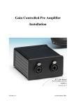
4.1 Hardware structure
The ICP DAS USB I/O provides various types of input and output. The I/O is handled
by embedded controller. The hardware structure is shown in figure 4-1 below.
ICP DAS USB IO
DI
Embedded
controller
DO
AI
External
Memory
EEPROM
AO
PI
Input / Output
USB Host (Computers)
FPGA
PO
4.2 Software structure
In the programmer point of view, the ICP DAS provides a class library to user to
develop project quickly and easily. The structure of the software is shown in figure 4-2.
The methods of USB classes are divided into 4 groups, base, digital I/O, analog I/O and
pulse I/O. The figures 4-3~4-7 show an overview to use ICP DAS USB I/O class library.
45
Document version: 1.09
Operation / Software structure
Class
Initialization
OpenDevice
{
Class
Initialization
C++
Access I/O
DI_...
DO_...
AI_...
AO_...
PI_...
PO_...
ICPDAS_USBIO m_USBIO;
C#
ICPDAS_USBIO m_USBIO = new ICPDAS_USBIO();
VB
Dim m_USBIO As ICPDAS_USBIO
Set m_USBIO = New ICPDAS_USBIO
46
Document version: 1.09
CloseDevice
Operation / Software structure
{
{
{
OpenDevice
Access I/O
CloseDevice
C++
m_USBIO.OpenDevice(…);
C#
m_USBIO.OpenDevice(…);
VB
Call m_USBIO.OpenDevice(…)
C++
m_USBIO.AI_ReadValue(…);
C#
m_USBIO.AI_ReadValue(…);
VB
Call m_USBIO.AI_ReadValue(…)
C++
m_USBIO.CloseDevice();
C#
m_USBIO.CloseDevice();
VB
Call m_USBIO.CloseDevice
47
Document version: 1.09
ICP DAS USB Class Members / Table of Constructors
5
ICP DAS USB Class Members
The members of the ICPDAS_USBIO class are divided into constructors, static and
public methods. The constructors initialize and create the instance of the ICPDAS_USBIO.
Static methods are the ways to identify or scan what USB modules are connected. Public
methods are used to access USB modules. The following tables list the members of
ICPDAS_USBIO class. The detail of these will be described in the following section.
5.1 Table of Constructors
Name
Description
ICPDAS_USBIO
Initializes a new instance of the ICPDAS_USBIO class.
5.2 Table of Static Methods
Name
Description
ListDevice
List all devices connected with local PC.
ScanDevice
Scan devices connected with local PC
5.3 Table of Public Methods
5.3.1 System
Name
Description
OpenDevice
List all devices connected with local PC.
CloseDevice
Scan devices connected with local PC.
SYNCDevice
Send a synchronization packet to clear software
WDT.
SetCommTimeout
Set communication timeout.
GetCommTimeout
Get communication timeout.
SetAutoResetWDT
Enable / disable automatic reset of the WDT
48
Document version: 1.09
ICP DAS USB Class Members / Table of Public Methods
5.3.2 Device
Name
Description
RefreshDeviceInfo
Refresh device information.
GetSoftWDTTimeout
Get software WDT timeout.
GetDeviceID
Get ID of the device.
GetFwVer
Get firmware version of the device.
GetDeviceNickName
Get nick name of the device.
GetDeviceSN
Get serial number of the device.
GetSupportIOMask
Get the mask of this device IO distribution.
GetDITotal
Get DI total channel of the device.
GetDOTotal
Get DO total channel of the device.
GetAITotal
Get AI total channel of the device.
GetAOTotal
Get AO total channel of the device.
GetPITotal
Get PI total channel of the device.
GetPOTotal
Get PO total channel of the device.
SetUserDefinedBoardID
Set board ID of this device.
SetDeviceNickName
Set nick name of this device.
SetSoftWDTTimeout
Set software WDT timeout.
LoadDefault
Load default setting.
StopBulk
Stop current bulk process.
RegisterEmergencyPktEventHandle
Register the callback function for emergency event
sent from USBIO.
5.3.3 Digital Input
Name
Description
DI_GetDigitalFilterWidth
Digital Input function - Get DI Digital Filter Width
DI_GetDigitalValueInverse
Digital Input function - Get DI Value Inverse
DI_GetCntEdgeTrigger
Digital Input function - Get DI Counter Edge Trigger
DI_ReadValue
Digital Input function - Read DI Value
DI_ReadCounterValue
Digital Input function - Read DI Counter Value
DI_SetDigitalFilterWidth
Digital Input function - Set DI Digital Filter Width
DI_SetDigitalValueInverse
Digital Input function - Set DI Value Inverse
DI_SetCntEdgeTrigger
Digital Input function - Set DI Counter Edge Trigger
DI_WriteClearCounter
Digital Input function - Clear Specified Channel of DI
49
Document version: 1.09
ICP DAS USB Class Members / Table of Public Methods
Counter Value
DI_WriteClearCounters
Digital Input function - Clear DI Counter Value with
Clear Mask
5.3.4 Digital Output
Name
Description
DO_GetPowerOnEnable
Digital Output function - Get Power-On Enable
DO_GetSafetyEnable
Digital Output function - Get Safety Enable
DO_GetSafetyValue
Digital Output function - Get Safety Value
DO_ReadValue
Digital Output function - Read DO Value
DO_SetPowerOnEnable
Digital Output function - Set Power-On Enable
DO_SetSafetyEnable
Digital Output function - Set Safety Enable
DO_SetSafetyValue
Digital Output function - Set Safety Value
DO_WriteValue
Digital Output function - Write DO Value
5.3.5 Analog Input
Name
AI_GetTotalSupportType
Description
Analog input function - Get total supported
amount.
AI_GetSupportTypeCode
Analog input function - Get supported type code.
AI_GetTypeCode
Analog input function - Get type code.
AI_GetChCJCOffset
Analog input function - Get channel CJC offset.
AI_GetChEnable
Analog input function - Get channel enable/disable.
AI_GetFilterRejection
Analog input function - Get filter rejection.
AI_GetCJCOffset
Analog input function - Get CJC offset.
AI_GetCJCEnable
Analog input function - Get CJC enable.
AI_GetWireDetectEnable
Analog input function - Get wire detect enable.
AI_GetResolution
Analog input function - Get resolution.
AI_ReadValue
AI_ReadBulkValue
AI_ReadCJCValue
AI_SetTypeCode
Analog input function - Read AI value in double
word format. (Overload)
Analog input function - Read bulk AI value (Fast
acquire functionality)
Analog input function - Get CJC value.
Analog input function - Set type code for specific
channel. (Overload)
50
Document version: 1.09
ICP DAS USB Class Members / Table of Public Methods
AI_SetChCJCOffset
Analog input function - Set channel CJC offset for
specific channel. (Overload)
AI_SetChEnable
Analog input function - Set channel enable/disable.
AI_SetFilterRejection
Analog input function - Set filter rejection.
AI_SetCJCOffset
Analog input function - Set CJC offset.
AI_SetCJCEnable
Analog input function - Set CJC enable.
AI_SetWireDetectEnable
Analog input function - Set wire detect enable.
5.3.6 Pulse Input
Name
Description
PI_GetTotalSupportType
Pulse input function - Get total supported amount.
PI_GetSupportTypeCode
Pulse input function - Get supported type code.
PI_GetTypeCode
Pulse input function - Get type code.
PI_GetTriggerMode
Pulse input function - Get trigger mode.
PI_GetLPFilterEnable
Pulse input function - Get low-pass filter enable.
PI_GetChIsolatedFlag
Pulse input function - Get channel isolated flag.
PI_GetLPFilterWidth
Pulse input function - Get low-pass filter width.
PI_ReadValue
Pulse input function - Read PI value.
PI_ReadCntValue
PI_ReadFreqValue
PI_ReadBulkValue
PI_SetTypeCode
PI_ClearChCount
PI_ClearSinglelChCount
PI_ClearChStatus
Pulse input function - Read the count value of
counters
Pulse input function - Read the frequency value of
counters
Pulse input function - Get bulk PI value (Fast
acquire functionality)
Pulse input function - Set type code for specific
channel. (Overload)
Pulse input function - Clear channel count with
clear mask.
Pulse input function - Clear single channel count.
Pulse input function - Clear channel status with
clear mask.
PI_ClearSinglelChStatus
Pulse input function - Clear single channel status.
PI_SetTriggerMode
Pulse input function - Set trigger mode. (Overload)
PI_SetChIsolatedFlag
PI_SetLPFilterEnable
Pulse input function - Set channel isolated flag.
(Overload)
Pulse input function - Set low-pass filter enable.
51
Document version: 1.09
ICP DAS USB Class Members / Constructors
(Overload)
PI_SetLPFilterWidth
Pulse input function - Set low-pass filter width.
(Overload)
5.3.7 Other
Name
Description
GetCurrentAccessObj
INTERNAL USE. DO NOT USE THIS METHOD.
SetNormalPktByteArray
INTERNAL USE. DO NOT USE THIS METHOD.
SetActivePktByteArray
INTERNAL USE. DO NOT USE THIS METHOD.
ClearActivePktBuffer
INTERNAL USE. DO NOT USE THIS METHOD.
GetActivePktByteArray
INTERNAL USE. DO NOT USE THIS METHOD.
SetNormalPktEvent
INTERNAL USE. DO NOT USE THIS METHOD.
IsDevMonitorThreadStop
INTERNAL USE. DO NOT USE THIS METHOD.
IsCommWithDevice
INTERNAL USE. DO NOT USE THIS METHOD.
GetLastCmdTime
INTERNAL USE. DO NOT USE THIS METHOD.
5.4 Constructors
5.4.1 ICPDAS_USBIO
Initialize a new instance of the ICPDAS_USBIO class.
Syntax
public ICPDAS_USBIO (
void
)
Example
ICPDAS_USBIO m_usbIO;
m_usbIO = new ICPDAS_USBIO();
52
Document version: 1.09
ICP DAS USB Class Members / Static Methods
5.5 Static Methods
5.5.1 ListDevice
List all devices connected to local PC.
Syntax
public byte ListDevice (
WORD *o_wDID,
BYTE *o_byBID
)
Parameters
*o_wDID
[OUT] An array of device ID for all devices
*o_byBID
[OUT] An array of board ID for all devices
Return Value
Number of devices connected with PC
Example
BYTE byNumDevice, byBIDs[127];
WORD wDIDs[127];
byNumDevice = ICPDAS_USBIO.ListDevice(&wDIDs, &byBIDs);
53
Document version: 1.09
ICP DAS USB Class Members / Static Methods
5.5.2 ScanDevice
Scanning device connected to PC. This static method just refreshes the list of the ICP
DAS USB series I/O modules, it is necessary to call ListDevice() to refresh new list.
Syntax
public int ScanDevice (
void
)
Parameters
none
Return Value
Error code
Example
ICPDAS_USBIO.ScanDevice();
54
Document version: 1.09
ICP DAS USB Class Members / Public Methods
5.6 Public Methods
5.6.1 System
5.6.1.1 OpenDevice
Open USBIO with device ID and board ID. The device ID is defined by the header
ICPDAS_USBIO.h or the enumeration in ICPDAS_USBIO.
Syntax
public int OpenDevice (
WORD i_wUSBIO_DID,
BYTE i_byUSBIO_BID
)
Parameters
i_wUSBIO_DID
[IN] Device ID for the specific device to open (Defined in ICPDAS_USBIO.h)
i_byUSBIO_BID
[IN] Board ID for the specific device to open
Return Value
Error code
Example
Int iErrCode;
ICPDAS_USBIO m_usbIO;
m_usbIO = new ICPDAS_USBIO();
iErrCode = m_usbIO.OpenDevice(USB2019, 1);
iErrCode = m_usbIO.CloseDevice();
55
Document version: 1.09
ICP DAS USB Class Members / Public Methods
5.6.1.2 CloseDevice
Close device and release resource.
Syntax
public int CloseDevice (
void
)
Parameters
none
Return Value
Error code
Example
Int iErrCode
ICPDAS_USBIO m_usbIO;
m_usbIO = new ICPDAS_USBIO();
if (ERR_NO_ERR == (iErrCode = m_usbIO.OpenDevice(USB2019, 1)))
{
// Some code accessing USB I/O
iErrCode = m_usbIO.CloseDevice();
}
56
Document version: 1.09
ICP DAS USB Class Members / Public Methods
5.6.1.3 SYNCDevice
Send synchronization packet to I/O module.
Note 1: The synchronization will be handled by library automatically after calling
OpenDevice, the synchronization will be closed after calling CloseDevice. User can call
this API to send synchronization packet manually, and it will not stop the original
synchronization.
Syntax
public int SYNCDevice (
void
)
Parameters
none
Return Value
Error code
Example
Int iErrCode
ICPDAS_USBIO m_usbIO;
m_usbIO = new ICPDAS_USBIO();
if (ERR_NO_ERR == (iErrCode = m_usbIO.OpenDevice(USB2019, 1)))
{
If(ERR_NO_ERR != (iErrCode = m_usbIO.SYNCDevice()))
printf(“%d”, iErrCode);
iErrCode = m_usbIO.CloseDevice();
}
57
Document version: 1.09
ICP DAS USB Class Members / Public Methods
5.6.1.4 SetCommTimeout
Set the communication timeout between packet send and receive.
Note 1: The timeout value will affect communication. If the timeout is small, it means the
communication is timeout after the value passed.
Note 2: The default value when first initial an ICP DAS USB I/O is 100ms.
Syntax
public int SetCommTimeout (
DWORD i_dwCommTimeout
)
Parameters
i_dCommTimeout
[IN] The communication timeout in millisecond(ms)
Return Value
Error code
Example
Int iErrCode
ICPDAS_USBIO m_usbIO;
m_usbIO = new ICPDAS_USBIO();
if(ERR_NO_ERR != (iErrCode = m_usbIO.SetCommTimeout(1000)))
printf(“%d”, iErrCode)
58
Document version: 1.09
ICP DAS USB Class Members / Public Methods
5.6.1.5 GetCommTimeout
Get the communication timeout between packet send and receive.
Note 1: The timeout value will affect communication. If the timeout is small, it means the
communication is timeout after the value passed.
Note 2: The default value when first initial an ICP DAS USB I/O is 100ms.
Syntax
public int GetCommTimeout (
DWORD* o_dwCommTimeout
)
Parameters
o_dCommTimeout
[OUT] The communication timeout in millisecond(ms)
Return Value
Error code
Example
Int iErrCode
ICPDAS_USBIO m_usbIO;
DWORD o_dwCommTimeout;
m_usbIO = new ICPDAS_USBIO();
if (ERR_NO_ERR == (iErrCode = m_usbIO.SetCommTimeout(1000)))
if(ERR_NO_ERR != (iErrCode = m_usbIO. GetCommTimeout (&o_dwCommTimeout)))
printf(“%d”, iErrCode);
else
printf(“%d\n”, o_dwCommTimeout);
59
Document version: 1.09
ICP DAS USB Class Members / Public Methods
5.6.1.6 SetAutoResetWDT
Enable / disable the handle of watchdog by library.
The library takes care of the watchdog automatically when first loaded. This advantage
brings an easy way to access with USB modules. But in other side, sometimes users want
to handle watchdog themselves. This API offers this functionality to disable the library to
automatically handle watchdog.
NOTE1: The library will return to automatic when open device. This means users have to
disable when open device.
Syntax
public int SetAutoResetWDT (
BOOL i_bEnable
)
Parameters
i_bEnable
[IN] To enable / disable the library to automatically handle watchdog.
Return Value
Error code
Example
Int iErrCode
ICPDAS_USBIO m_usbIO;
m_usbIO = new ICPDAS_USBIO();
if (ERR_NO_ERR == (iErrCode = m_usbIO.OpenDevice(USB2019, 1)))
{
If(ERR_NO_ERR != (iErrCode = m_usbIO.SetAutoResetWDT(FALSE)))
printf(“%d”, iErrCode);
}
60
Document version: 1.09
ICP DAS USB Class Members / Public Methods
5.6.2 Device
5.6.2.1 RefreshDeviceInfo
Refresh all information of this device.
Note 1: The RefreshDeviceInfo() will be called automatically when open device.
Note 2: This function will take time to refresh information.
Syntax
public int RefreshDeviceInfo (
void
)
Parameters
none
Return Value
Error code
Example
Int iErrCode
ICPDAS_USBIO m_usbIO;
m_usbIO = new ICPDAS_USBIO();
if(ERR_NO_ERR == (iErrCode = m_usbIO.OpenDevice(USB2019, 1)))
{
if(ERR_NO_ERR != iErrCode = m_usbIO.RefreshDeviceInfo()))
printf(“%d”, iErrCode)
iErrCode = m_usbIO.CloseDevice();
}
61
Document version: 1.09
ICP DAS USB Class Members / Public Methods
5.6.2.2 GetSoftWDTTimeout
Get the software WDT timeout of I/O module.
Syntax
public int GetSoftWDTTimeout (
DWORD *o_dwSoftWDTTimeout
)
Parameters
*o_dwSoftWDTTimeout
[OUT] The software WDT timeout in millisecond(ms)
Return Value
Error code
Example
Int iErrCode
ICPDAS_USBIO m_usbIO;
DWORD o_dwSoftWDTTimeout;
m_usbIO = new ICPDAS_USBIO();
if(ERR_NO_ERR == (iErrCode = m_usbIO.OpenDevice(USB2019, 1)))
{
if(ERR_NO_ERR != iErrCode = m_usbIO. GetSoftWDTTimeout (&o_dwSoftWDTTimeout)))
printf(“%d”,iErrCode);
else
printf(“%d\n”, o_dwCommTimeout);
iErrCode = m_usbIO.CloseDevice();
}
62
Document version: 1.09
ICP DAS USB Class Members / Public Methods
5.6.2.3 GetDeviceID
Get ID of the device.
Syntax
public int GetDeviceID (
DWORD *o_dwDeviceID
)
Parameters
*o_dwDeviceID
[OUT] The device ID
Return Value
Error code
Example
Int iErrCode
ICPDAS_USBIO m_usbIO;
DWORD o_dwDeviceID;
m_usbIO = new ICPDAS_USBIO();
if(ERR_NO_ERR == (iErrCode = m_usbIO.OpenDevice(USB2019, 1)))
{
if(ERR_NO_ERR != (iErrCode = m_usbIO. GetDeviceID (&o_dwDeviceID)))
printf(“%d”, iErrCode);
else
printf(“%d”, o_dwDeviceID);
iErrCode = m_usbIO.CloseDevice();
}
63
Document version: 1.09
ICP DAS USB Class Members / Public Methods
5.6.2.4 GetFwVer
Get firmware version of the device.
Syntax
public int GetDeviceID (
WORD *o_ wFwVer
)
Parameters
*o_wFwVer
[OUT] The firmware version
Return Value
Error code
Example
Int iErrCode
ICPDAS_USBIO m_usbIO;
WORD o_wFwVer;
m_usbIO = new ICPDAS_USBIO();
if(ERR_NO_ERR == (iErrCode = m_usbIO.OpenDevice(USB2019, 1)))
{
if(ERR_NO_ERR != (iErrCode = m_usbIO. GetFwVer (&o_wFwVer)))
printf(“%d”, iErrCode);
else
printf(“%d”,o_wDwVer);
iErrCode = m_usbIO.CloseDevice();
}
64
Document version: 1.09
ICP DAS USB Class Members / Public Methods
5.6.2.5 GetDeviceNickName
Get nick name of the device.
Syntax
public int GetDeviceNickName (
BYTE *o_byDeviceNickName
)
Parameters
*o_byDeviceNickName
[OUT] The byte array of the nick name of the device
Return Value
Error code
Example
Int iErrCode
ICPDAS_USBIO m_usbIO;
Byte o_byDeviceNickName [USBIO_NICKNAME_LENGTH];
m_usbIO = new ICPDAS_USBIO();
if(ERR_NO_ERR == (iErrCode = m_usbIO.OpenDevice(USB2019, 1)))
{
if(ERR_NO_ERR != (iErrCode = m_usbIO. GetDeviceNickName (o_byDeviceNickName)))
printf(“%d”, iErrCode);
else
printf(“%s”, o_byDeviceNickName);
iErrCode = m_usbIO.CloseDevice();
}
65
Document version: 1.09
ICP DAS USB Class Members / Public Methods
5.6.2.6 GetDeviceSN
Get serial number of the device.
Syntax
public int GetDeviceSN (
BYTE *o_byDeviceSN
)
Parameters
*o_byDeviceSN
[OUT] The byte array of the serial number of the device
Return Value
Error code
Example
Int iErrCode
ICPDAS_USBIO m_usbIO;
Byte o_byDeviceSN [USBIO_SN_LENGTH];
m_usbIO = new ICPDAS_USBIO();
if(ERR_NO_ERR == (iErrCode = m_usbIO.OpenDevice(USB2019, 1)))
{
if(ERR_NO_ERR != (iErrCode = m_usbIO. GetDeviceSN (o_ byDeviceSN)))
printf(“%d”, iErrCode);
else
printf(“%s”, o_ byDeviceSN);
iErrCode = m_usbIO.CloseDevice();
}
66
Document version: 1.09
ICP DAS USB Class Members / Public Methods
5.6.2.7 GetSupportIOMask
Get the mask of this device IO distribution. Each bit of the mask indicates each
supported IO type as shown in the following table.
Bit7
Bit6
Bit5
Bit4
Bit3
Bit2
Bit1
Bit0
N/A
N/A
PI
PO
AI
AO
DI
DO
This mask can help you to identify what types of IO are supported in the device.
Syntax
public int GetSupportIOMask (
BYTE *o_bySupportIOMask
)
Parameters
*o_bySupportIOMask
[OUT] The support IO mask of the device
Return Value
Error code
67
Document version: 1.09
ICP DAS USB Class Members / Public Methods
Example
Int iErrCode
ICPDAS_USBIO m_usbIO;
Byte o_bySupportIOMask;
m_usbIO = new ICPDAS_USBIO();
if(ERR_NO_ERR == (iErrCode = m_usbIO.OpenDevice(USB2019, 1)))
{
if(ERR_NO_ERR != (iErrCode = m_usbIO. GetSupportIOMask (&o_bySupportIOMask)))
printf(“%d”, iErrCode);
else
printf(“0x%02x”,o_bySupportIOMask);
iErrCode = m_usbIO.CloseDevice();
}
68
Document version: 1.09
ICP DAS USB Class Members / Public Methods
5.6.2.8 GetDITotal
Get DI total number of channels of the device.
Syntax
public int GetDITotal (
BYTE *o_byDITotal
)
Parameters
*o_byDITotal
[OUT] The DI total number of channels
Return Value
Error code
Example
Int iErrCode
ICPDAS_USBIO m_usbIO;
Byte o_byDITotal;
m_usbIO = new ICPDAS_USBIO();
if(ERR_NO_ERR == (iErrCode = m_usbIO.OpenDevice(USB20xx, 1)))
{
if(ERR_NO_ERR != (iErrCode = m_usbIO. GetDITotal (&o_byDITotal)))
printf(“%d”, iErrCode);
else
printf(“%d”,o_byDITotal);
iErrCode = m_usbIO.CloseDevice();
}
69
Document version: 1.09
ICP DAS USB Class Members / Public Methods
5.6.2.9 GetDOTotal
Get DO total number of channels of the device.
Syntax
public int GetDOTotal (
BYTE *o_byDOTotal
)
Parameters
*o_byDOTotal
[OUT] The DO total number of channels
Return Value
Error code
Example
Int iErrCode
ICPDAS_USBIO m_usbIO;
Byte o_byDOTotal;
m_usbIO = new ICPDAS_USBIO();
if(ERR_NO_ERR == (iErrCode = m_usbIO.OpenDevice(USB20xx, 1)))
{
if(ERR_NO_ERR != (iErrCode = m_usbIO. GetDOTotal (&o_byDOTotal)))
printf(“%d”, iErrCode);
else
printf(“%d”,o_byDOTotal);
iErrCode = m_usbIO.CloseDevice();
}
70
Document version: 1.09
ICP DAS USB Class Members / Public Methods
5.6.2.10 GetAITotal
Get AI total number of channels of the device.
Syntax
public int GetAITotal (
BYTE *o_byAITotal
)
Parameters
*o_byAITotal
[OUT] The AI total number of channels
Return Value
Error code
Example
Int iErrCode
ICPDAS_USBIO m_usbIO;
Byte o_byAITotal;
m_usbIO = new ICPDAS_USBIO();
if(ERR_NO_ERR == (iErrCode = m_usbIO.OpenDevice(USB20xx, 1)))
{
if(ERR_NO_ERR != (iErrCode = m_usbIO. GetAITotal (&o_byAITotal)))
printf(“%d”, iErrCode);
else
printf(“%d”,o_byAITotal);
iErrCode = m_usbIO.CloseDevice();
}
71
Document version: 1.09
ICP DAS USB Class Members / Public Methods
5.6.2.11 GetAOTotal
Get AO total number of channels of the device.
Syntax
public int GetAOTotal (
BYTE *o_byAOTotal
)
Parameters
*o_byAOTotal
[OUT] The AO total number of channels
Return Value
Error code
Example
Int iErrCode
ICPDAS_USBIO m_usbIO;
Byte o_byAOTotal;
m_usbIO = new ICPDAS_USBIO();
if(ERR_NO_ERR == (iErrCode = m_usbIO.OpenDevice(USB20xx, 1)))
{
if(ERR_NO_ERR != (iErrCode = m_usbIO. GetAOTotal (&o_byAOTotal)))
printf(“%d”, iErrCode);
else
printf(“%d”,o_byAOTotal);
iErrCode = m_usbIO.CloseDevice();
}
72
Document version: 1.09
ICP DAS USB Class Members / Public Methods
5.6.2.12 GetPITotal
Get PI total number of channels of the device.
Syntax
public int GetPITotal (
BYTE *o_byPITotal
)
Parameters
*o_byPITotal
[OUT] The PI total number of channels
Return Value
Error code
Example
Int iErrCode
ICPDAS_USBIO m_usbIO;
Byte o_byPITotal;
m_usbIO = new ICPDAS_USBIO();
if(ERR_NO_ERR == (iErrCode = m_usbIO.OpenDevice(USB20xx, 1)))
{
if(ERR_NO_ERR != (iErrCode = m_usbIO. GetPITotal (&o_byPITotal)))
printf(“%d”, iErrCode);
else
printf(“%d”,o_byPITotal);
iErrCode = m_usbIO.CloseDevice();
}
73
Document version: 1.09
ICP DAS USB Class Members / Public Methods
5.6.2.13 GetPOTotal
Get PO total number of channels of the device.
Syntax
public int GetPOTotal (
BYTE *o_byPOTotal
)
Parameters
*o_byPOTotal
[OUT] The PO total number of channels
Return Value
Error code
Example
Int iErrCode
ICPDAS_USBIO m_usbIO;
Byte o_byPOTotal;
m_usbIO = new ICPDAS_USBIO();
if(ERR_NO_ERR == (iErrCode = m_usbIO.OpenDevice(USB20xx, 1)))
{
if(ERR_NO_ERR != (iErrCode = m_usbIO. GetPOTotal (&o_byPOTotal)))
printf(“%d”, iErrCode);
else
printf(“%d”,o_byPOTotal);
iErrCode = m_usbIO.CloseDevice();
}
74
Document version: 1.09
ICP DAS USB Class Members / Public Methods
5.6.2.14 SetUserDefinedBoardID
Set board ID of this device. The valid value of the ID is from 16 to 127.
Syntax
public int SetUserDefinedBoardID (
BYTE i_byBID
)
Parameters
i_byBID
[IN] The board ID to set
Return Value
Error code
Example
Int iErrCode
ICPDAS_USBIO m_usbIO;
m_usbIO = new ICPDAS_USBIO();
if(ERR_NO_ERR == (iErrCode = m_usbIO.OpenDevice(USB20xx, 1)))
{
if(ERR_NO_ERR != (iErrCode = m_usbIO. SetUserDefinedBoardID (123)))
printf(“%d”, iErrCode);
iErrCode = m_usbIO.CloseDevice();
}
75
Document version: 1.09
ICP DAS USB Class Members / Public Methods
5.6.2.15 SetDeviceNickName
Set nick name of this device. The maximum number of the character of this device is 32.
Syntax
public int SetDeviceNickName (
BYTE *i_byDeviceNickName
)
Parameters
*i_byDeviceNickName
[IN] The byte array of the nick name to set
Return Value
Error code
Example
Int iErrCode
ICPDAS_USBIO m_usbIO;
Byte byNickName[USBIO_NICKNAME_LENGTH];
m_usbIO = new ICPDAS_USBIO();
if(ERR_NO_ERR == (iErrCode = m_usbIO.OpenDevice(USB20xx, 1)))
{
sprintf(byNickName, “Station 1-1-3”);
if(ERR_NO_ERR != (iErrCode = m_usbIO. SetDeviceNickName (byNickName)))
printf(“%d”, iErrCode);
iErrCode = m_usbIO.CloseDevice();
}
76
Document version: 1.09
ICP DAS USB Class Members / Public Methods
5.6.2.16 SetSoftWDTTimeout
Set the software WDT timeout.
The minimum value of timeout is 100ms, and maximum is 30 minutes.
Syntax
public int SetSoftWDTTimeout (
DWORD i_dwSoftWDTTimeout
)
Parameters
i_dwSoftWDTTimeout
[IN] The software WDT timeout in millisecond(ms)
Return Value
Error code
Example
Int iErrCode
ICPDAS_USBIO m_usbIO;
m_usbIO = new ICPDAS_USBIO();
if(ERR_NO_ERR == (iErrCode = m_usbIO.OpenDevice(USB20xx, 1)))
{
if(ERR_NO_ERR != (iErrCode = m_usbIO. SetSoftWDTTimeout (1000)))
printf(“%d”, iErrCode);
iErrCode = m_usbIO.CloseDevice();
}
77
Document version: 1.09
ICP DAS USB Class Members / Public Methods
5.6.2.17 LoadDefault
Load default setting.
Syntax
public int LoadDefault (
void
)
Parameters
none
Return Value
Error code
Example
Int iErrCode
ICPDAS_USBIO m_usbIO;
m_usbIO = new ICPDAS_USBIO();
if (ERR_NO_ERR == (iErrCode = m_usbIO.OpenDevice(USB20xx, 1)))
{
If(ERR_NO_ERR != (iErrCode = m_usbIO.LoadDefault ()))
printf(“%d”, iErrCode);
iErrCode = m_usbIO.CloseDevice();
}
78
Document version: 1.09
ICP DAS USB Class Members / Public Methods
5.6.2.18 StopBulk
Stop current bulk process.
Syntax
public int LoadDefault (
void
)
Parameters
none
Return Value
Error code
Example
Int iErrCode
ICPDAS_USBIO m_usbIO;
m_usbIO = new ICPDAS_USBIO();
if (ERR_NO_ERR == (iErrCode = m_usbIO.OpenDevice(USB20xx, 1)))
{
If(ERR_NO_ERR != (iErrCode = m_usbIO.StopBulk ()))
printf(“%d”, iErrCode);
iErrCode = m_usbIO.CloseDevice();
}
79
Document version: 1.09
ICP DAS USB Class Members / Public Methods
5.6.2.19 RegisterEmergencyPktEventHandle
Register the callback function for emergency event sent from USBIO.
When in callback operation, it will cause the performance in your callback function.
Please reduce execute time in this callback function.
Syntax
public int RegisterEmergencyPktEventHandle (
OnEmergencyPktArriveEvent i_evtHandle
)
Parameters
i_evtHandle
[IN] The callback function for emergency event
Return Value
Error code
80
Document version: 1.09
ICP DAS USB Class Members / Public Methods
Example
Int iErrCode
ICPDAS_USBIO m_usbIO;
Bool m_bEmcyPktArrive;
Byte byEmcyPkt[USBIO_MAX_PACKET_LENGTH];
Void emcypkeEvt(Byte* byData, Byte byLen)
{
m_ bEmcyPktArrive = true;
memcpy(byEmcyPkt, byData, byLen);
}
m_usbIO = new ICPDAS_USBIO();
if (ERR_NO_ERR == (iErrCode = m_usbIO.OpenDevice(USB20xx, 1)))
{
If(ERR_NO_ERR != (iErrCode = m_usbIO.RegisterEmergencyPktEventHandle (emcypkeEvt)))
printf(“%d”, iErrCode);
while(1)
{
// User’s application loop
If(m_ bEmcyPktArrive)
{
// Handle emcy packet
}
}
iErrCode = m_usbIO.CloseDevice();
}
81
Document version: 1.09
ICP DAS USB Class Members / Public Methods
5.6.3 Digital Input
5.6.3.1 DI_GetDigitalFilterWidth
Digital input function - Get DI Digital Filter Width. The digital filter width is used for
filtering the noise or the glitch. The unit of the filter is 0.1 milli-second.
Syntax
public int DI_GetDigitalFilterWidth (
WORD* o_wFilterWidth
)
Parameters
*o_wFilterWidth
[OUT] The digital filter width (The unit is 0.1 ms)
Return Value
Error code
82
Document version: 1.09
ICP DAS USB Class Members / Public Methods
Example
Int iErrCode
ICPDAS_USBIO m_usbIO;
WORD o_wFilterWidth;
Int iIdx;
Bool bRet = true;
m_usbIO = new ICPDAS_USBIO();
if(ERR_NO_ERR == (iErrCode = m_usbIO.OpenDevice(USB2051, 1)))
{
if(ERR_NO_ERR != (iErrCode = m_usbIO.DI_GetDigitalFilterWidth (&o_wFilterWidth)))
{
printf(“%d”, iErrCode);
bRet = false;
}
If(bRet)
{
printf(“%d\n”, o_wFilterWidth);
}
}
83
Document version: 1.09
ICP DAS USB Class Members / Public Methods
5.6.3.2 DI_GetDigitalValueInverse
Digital input function - Get DI Value Inverse.
Inverse
Value
No
0
Yes
1
Syntax
public int DI_GetDigitalValueInverse (
DWORD* o_dwInverse
)
Parameters
*o_dwInverse
[OUT] The inverse setting
Return Value
Error code
84
Document version: 1.09
ICP DAS USB Class Members / Public Methods
Example
Int iErrCode
ICPDAS_USBIO m_usbIO;
DWORD o_dwInverse;
Int iIdx;
Bool bRet = true;
m_usbIO = new ICPDAS_USBIO();
if(ERR_NO_ERR == (iErrCode = m_usbIO.OpenDevice(USB2051, 1)))
{
if(ERR_NO_ERR != (iErrCode = m_usbIO.DI_GetDigitalValueInverse (&o_dwInverse)))
{
printf(“%d”, iErrCode);
bRet = false;
}
If(bRet)
{
printf(“%d\n”, o_dwInverse);
}
}
85
Document version: 1.09
ICP DAS USB Class Members / Public Methods
5.6.3.3 DI_GetCntEdgeTrigger
Digital input function - Get DI Counter Edge Trigger. This edge trigger is used for the
counting operation of the counter.
Edge Trigger
Value
Falling
0
Rising
1
Syntax
public int DI_GetCntEdgeTrigger (
DWORD* o_dwEdgeTrig
)
Parameters
*o_dwEdgeTrig
[OUT] The counter edge trigger setting
Return Value
Error code
86
Document version: 1.09
ICP DAS USB Class Members / Public Methods
Example
Int iErrCode
ICPDAS_USBIO m_usbIO;
DWORD o_dwEdgeTrig;
Int iIdx;
Bool bRet = true;
m_usbIO = new ICPDAS_USBIO();
if(ERR_NO_ERR == (iErrCode = m_usbIO.OpenDevice(USB2051, 1)))
{
if(ERR_NO_ERR != (iErrCode = m_usbIO.DI_GetCntEdgeTrigger (&o_dwEdgeTrig)))
{
printf(“%d”, iErrCode);
bRet = false;
}
If(bRet)
{
printf(“%d\n”, o_dwEdgeTrig);
}
}
87
Document version: 1.09
ICP DAS USB Class Members / Public Methods
5.6.3.4 DI_ReadValue
Digital Input function - Read DI Value. The values of digital input channels in byte array
format.
Syntax
public int DI_ReadValue (
BYTE* o_byDIValue
)
Parameters
*o_byDIValue
[OUT] The byte arrays of the DI value
Return Value
Error code
88
Document version: 1.09
ICP DAS USB Class Members / Public Methods
Example
Int iErrCode
ICPDAS_USBIO m_usbIO;
BYTE o_byDIValue[USBIO_DI_MAX_CHANNEL];
Int iIdx;
Bool bRet = true;
m_usbIO = new ICPDAS_USBIO();
if(ERR_NO_ERR == (iErrCode = m_usbIO.OpenDevice(USB2051, 1)))
{
if(ERR_NO_ERR != (iErrCode = m_usbIO.DI_ReadValue (o_byDIValue)))
{
printf(“%d”, iErrCode);
bRet = false;
}
If(bRet)
{
for(iIdx = 0; iIdx < (USBIO_DI_MAX_CHANNEL >> 3); iIdx++)
printf(“%d\n”, o_byDIValue[iIdx]);
}
}
89
Document version: 1.09
ICP DAS USB Class Members / Public Methods
5.6.3.5 DI_ReadCounterValue
Digital Input function - Read DI Counter Value. The counting value of the digital input
counter in word array format.
Syntax
public int DI_ReadCounterValue (
WORD* o_wDICntValue
)
Parameters
*o_wDICntValue
[OUT] The word arrays of the DI counter value
Return Value
Error code
90
Document version: 1.09
ICP DAS USB Class Members / Public Methods
Example
Int iErrCode
ICPDAS_USBIO m_usbIO;
WORD o_wDICntValue[USBIO_DI_MAX_CHANNEL];
Int iIdx;
Bool bRet = true;
m_usbIO = new ICPDAS_USBIO();
if(ERR_NO_ERR == (iErrCode = m_usbIO.OpenDevice(USB2051, 1)))
{
if(ERR_NO_ERR != (iErrCode = m_usbIO.DI_ReadCounterValue (o_wDICntValue)))
{
printf(“%d”, iErrCode);
bRet = false;
}
If(bRet)
{
for(iIdx = 0; iIdx < (USBIO_DI_MAX_CHANNEL >> 3); iIdx++)
printf(“%d\n”, o_wDICntValue[iIdx]);
}
}
91
Document version: 1.09
ICP DAS USB Class Members / Public Methods
5.6.3.6 DI_SetDigitalFilterWidth
Digital input function - Set DI Digital Filter Width. Used for setting the filter width for the
digital input. The unit of the filter width is 0.1 milli-second.
Syntax
public int DI_SetDigitalFilterWidth (
WORD* i_wFilterWidth
)
Parameters
*i_wFilterWidth
[IN] The digital filter width (The unit is 0.1 ms)
Return Value
Error code
Example
Int iErrCode
ICPDAS_USBIO m_usbIO;
m_usbIO = new ICPDAS_USBIO();
if(ERR_NO_ERR == (iErrCode = m_usbIO.OpenDevice(USB2051, 1)))
{
if(ERR_NO_ERR != (iErrCode = m_usbIO.DI_SetDigitalFilterWidth (10))
printf(“%d”, iErrCode);
m_usbIO.CloseDevice();
}
92
Document version: 1.09
ICP DAS USB Class Members / Public Methods
5.6.3.7 DI_SetDigitalValueInverse
Digital input function - Set DI Value Inverse.
Inverse
Value
No
0
Yes
1
Syntax
public int DI_SetDigitalValueInverse (
DWORD* i_dwInverse
)
Parameters
*i_dwInverse
[IN] The inverse setting
Return Value
Error code
Example
Int iErrCode
ICPDAS_USBIO m_usbIO;
m_usbIO = new ICPDAS_USBIO();
if(ERR_NO_ERR == (iErrCode = m_usbIO.OpenDevice(USB2051, 1)))
{
if(ERR_NO_ERR != (iErrCode = m_usbIO.DI_SetDigitalValueInverse (1))
printf(“%d”, iErrCode);
m_usbIO.CloseDevice();
}
93
Document version: 1.09
ICP DAS USB Class Members / Public Methods
5.6.3.8 DI_SetCntEdgeTrigger
Digital input function - Set DI Counter Edge Trigger.
Edge Trigger
Value
Falling
0
Rising
1
Syntax
public int DI_SetCntEdgeTrigger (
DWORD* i_dwEdgeTrig
)
Parameters
*i_dwEdgeTrig
[IN] The counter edge trigger setting
Return Value
Error code
Example
Int iErrCode
ICPDAS_USBIO m_usbIO;
m_usbIO = new ICPDAS_USBIO();
if(ERR_NO_ERR == (iErrCode = m_usbIO.OpenDevice(USB2051, 1)))
{
if(ERR_NO_ERR != (iErrCode = m_usbIO.DI_SetCntEdgeTrigger (1))
printf(“%d”, iErrCode);
m_usbIO.CloseDevice();
}
94
Document version: 1.09
ICP DAS USB Class Members / Public Methods
5.6.3.9 DI_WriteClearCounter
Digital input function - Clear specified channel of DI Counter Value.
Syntax
public int DI_WriteClearCounter (
BYTE* i_byChToClr
)
Parameters
*i_byChToClr
[IN] The counter channel for clearing
Return Value
Error code
Example
Int iErrCode
ICPDAS_USBIO m_usbIO;
m_usbIO = new ICPDAS_USBIO();
if(ERR_NO_ERR == (iErrCode = m_usbIO.OpenDevice(USB2051, 1)))
{
if(ERR_NO_ERR != (iErrCode = m_usbIO.DI_WriteClearCounter (1))
printf(“%d”, iErrCode);
m_usbIO.CloseDevice();
}
95
Document version: 1.09
ICP DAS USB Class Members / Public Methods
5.6.3.10 DI_WriteClearCounters
Digital input function - Clear DI Counter Value with Clear Mask.
Syntax
public int DI_WriteClearCounters (
DWORD* i_dwCntClrMask
)
Parameters
*i_dwCntClrMask
[IN] The counter clear mask
Return Value
Error code
Example
Int iErrCode
ICPDAS_USBIO m_usbIO;
m_usbIO = new ICPDAS_USBIO();
if(ERR_NO_ERR == (iErrCode = m_usbIO.OpenDevice(USB2051, 1)))
{
if(ERR_NO_ERR != (iErrCode = m_usbIO.DI_WriteClearCounters (0x0000FFFF))
printf(“%d”, iErrCode);
m_usbIO.CloseDevice();
}
96
Document version: 1.09
ICP DAS USB Class Members / Public Methods
5.6.4 Digital Output
5.6.4.1 DO_GetPowerOnEnable
Digital Output function - Get Power-On Enable
Power-On Enable
Value
Disable & Off
0
Enable & On
1
Syntax
public int DO_GetPowerOnEnable(
BYTE* o_byPowerOnEnable
)
Parameters
*o_byPowerOnEnable
[OUT] The power-on enable mask. Each byte represents the power-on enable / disable configuration of
each channel.
Return Value
Error code
97
Document version: 1.09
ICP DAS USB Class Members / Public Methods
Example
Int iErrCode
ICPDAS_USBIO m_usbIO;
Byte o_byPowerOnEnable[USBIO_DO_MAX_CHANNEL];
Int iIdx;
Bool bRet = true;
m_usbIO = new ICPDAS_USBIO();
if(ERR_NO_ERR == (iErrCode = m_usbIO.OpenDevice(USB2064, 1)))
{
if(ERR_NO_ERR != (iErrCode = m_usbIO. DO_GetPowerOnEnable (&o_byPowerOnEnable)))
{
printf(“%d”, iErrCode);
bRet = false;
}
If(bRet)
{
for(iIdx = 0; iIdx <USBIO_DO_MAX_CHANNEL; iIdx++)
printf(“%02x\n”, o_byPowerOnEnable[iIdx]);
}
}
98
Document version: 1.09
ICP DAS USB Class Members / Public Methods
5.6.4.2 DO_GetSafetyEnable
Digital Output function - Get Safety Enable. Each channel takes one bit.
Safety Enable
Value
Disable
0
Enable
1
Syntax
public int DO_GetSafetyEnable (
BYTE* o_bySafetyEnables
)
Parameters
*o_bySafetyEnables
[OUT] The safety enable mask. Each bit of the mask represents the safety enable / disable configuration of
each channel
Return Value
Error code
99
Document version: 1.09
ICP DAS USB Class Members / Public Methods
Example
Int iErrCode
ICPDAS_USBIO m_usbIO;
Byte o_bySafetyEnable[(USBIO_DO_MAX_CHANNEL + 7] / 8];
Int iIdx;
Bool bRet = true;
m_usbIO = new ICPDAS_USBIO();
if(ERR_NO_ERR == (iErrCode = m_usbIO.OpenDevice(USB2064, 1)))
{
if(ERR_NO_ERR != (iErrCode = m_usbIO.DO_GetSafetyEnable(&o_bySafetyEnables))
{
printf(“%d”, iErrCode);
bRet = false;
}
If(bRet)
{
for(iIdx = 0; iIdx <((USBIO_DO_MAX_CHANNEL + 7] / 8); iIdx++)
printf(“%02x\n”, o_bySafetyEnables[iIdx]);
}
}
100
Document version: 1.09
ICP DAS USB Class Members / Public Methods
5.6.4.3 DO_GetSafetyValue
Digital Output function - Get Safety Value. Each channel takes one bit.
Safety Value
Value
Off
0
On
1
Syntax
public int DO_GetSafetyValue(
BYTE* o_bySafetyValue
)
Parameters
*o_bySafetyValue
[OUT] The safety value. Each bit represents the safety value of each channel.
Return Value
Error code
101
Document version: 1.09
ICP DAS USB Class Members / Public Methods
Example
Int iErrCode
ICPDAS_USBIO m_usbIO;
Byte o_bySafetyValue[(USBIO_DO_MAX_CHANNEL + 7] / 8];
Int iIdx;
Bool bRet = true;
m_usbIO = new ICPDAS_USBIO();
if(ERR_NO_ERR == (iErrCode = m_usbIO.OpenDevice(USB2064, 1)))
{
if(ERR_NO_ERR != (iErrCode = m_usbIO.DO_GetSafetyValue(&o_bySafetyValue))
{
printf(“%d”, iErrCode);
bRet = false;
}
If(bRet)
{
for(iIdx = 0; iIdx <((USBIO_DO_MAX_CHANNEL + 7] / 8); iIdx++)
printf(“%02x\n”, o_bySafetyValue[iIdx]);
}
}
102
Document version: 1.09
ICP DAS USB Class Members / Public Methods
5.6.4.4 DO_ReadValue
Digital Output function - Read DO Value
Syntax
public int DO_ReadValue(
BYTE* o_byDOValue
)
Parameters
*o_byDOValue
[OUT] The DO value. Each bit represents the DO value of each channel.
Return Value
Error code
103
Document version: 1.09
ICP DAS USB Class Members / Public Methods
Example
Int iErrCode
ICPDAS_USBIO m_usbIO;
Byte o_byDOValue[(USBIO_DO_MAX_CHANNEL + 7] / 8];
Int iIdx;
Bool bRet = true;
m_usbIO = new ICPDAS_USBIO();
if(ERR_NO_ERR == (iErrCode = m_usbIO.OpenDevice(USB2064, 1)))
{
if(ERR_NO_ERR != (iErrCode = m_usbIO.DO_ReadValue(&o_byDOValue))
{
printf(“%d”, iErrCode);
bRet = false;
}
If(bRet)
{
for(iIdx = 0; iIdx <((USBIO_DO_MAX_CHANNEL + 7] / 8); iIdx++)
printf(“%02x\n”, o_byDOValue[iIdx]);
}
}
104
Document version: 1.09
ICP DAS USB Class Members / Public Methods
5.6.4.5 DO_SetPowerOnEnable
The class has two overload methods for configuring power on functionality. One
provides specifying channel to set, another for all channel. These two overload methods
are listed as following table and described in following section.
Name of Methods
DO_SetPowerOnEnable( BYTE i_byChToSet, BYTE i_byPowerOnEnable )
DO_SetPowerOnEnable( BYTE* i_byPowerOnEnables )
105
Document version: 1.09
ICP DAS USB Class Members / Public Methods
5.6.4.5.1 DO_SetPowerOnEnable (BYTE, BYTE)
Digital Output function - Set Power-On enable for specific channel. The value of the
enable byte is listed below.
Power-On Enable
Value
Disable & Off
0
Enable & On
1
Syntax
public int DO_SetPowerOnEnable (
BYTE i_byChToSet,
BYTE i_byPowerOnEnable
)
Parameters
i_byChToSet
[IN] The specific channel to set
i_byTypeCode
[IN] The power-on enable for the specific channel
Return Value
Error code
106
Document version: 1.09
ICP DAS USB Class Members / Public Methods
Example
Int iErrCode
ICPDAS_USBIO m_usbIO;
m_usbIO = new ICPDAS_USBIO();
if(ERR_NO_ERR == (iErrCode = m_usbIO.OpenDevice(USB2064, 1)))
{
if(ERR_NO_ERR != (iErrCode = m_usbIO.DO_SetPowerOnEnable(0, 0x1)))
printf(“%d”, iErrCode);
iErrCode = m_usbIO.CloseDevice();
}
107
Document version: 1.09
ICP DAS USB Class Members / Public Methods
5.6.4.5.2 DO_SetPowerOnEnable (BYTE*)
Digital Output function - Set Power-On enable for all channel. The value of the enable
byte is listed below.
Power-On Enable
Value
Disable & Off
0
Enable & On
1
Syntax
public int DO_SetPowerOnEnable (
BYTE *i_byPowerOnEnables
)
Parameters
*i_byPowerOnEnables
[IN] The byte array of the power-on enable
Return Value
Error code
108
Document version: 1.09
ICP DAS USB Class Members / Public Methods
Example
Int iErrCode
ICPDAS_USBIO m_usbIO;
Byte i_byChPwrOn[USBIO_DO_MAX_CHANNEL];
Int iIdx;
m_usbIO = new ICPDAS_USBIO();
if(ERR_NO_ERR == (iErrCode = m_usbIO.OpenDevice(USB2064, 1)))
{
For(iIdx = 0; iIdx < USBIO_DO_MAX_CHANNEL; iIdx)
i_byChPwrOn[iIdx] = 0x1;
if(ERR_NO_ERR != (iErrCode = m_usbIO.DO_SetPowerOnEnable(i_byChPwrOn)))
printf(“%d”, iErrCode);
iErrCode = m_usbIO.CloseDevice();
}
109
Document version: 1.09
ICP DAS USB Class Members / Public Methods
5.6.4.6 DO_SetSafetyEnable
Digital Output function - Set Safety Enable. Each bit represents channel safety enable.
The value of the safety enable is shown below.
Safety Enable
Value
Disable
0
Enable
1
Syntax
public int DO_SetSafetyEnable(
BYTE* i_bySafetyEnable
)
Parameters
*i_bySafetyEnable
[IN] The safety enable mask. Each bit represents the safety configuration of each channel.
Return Value
Error code
110
Document version: 1.09
ICP DAS USB Class Members / Public Methods
Example
Int iErrCode
ICPDAS_USBIO m_usbIO;
Byte i_bySafetyEnable[(USBIO_DO_MAX_CHANNEL + 7] / 8];
Int iIdx;
Bool bRet = true;
m_usbIO = new ICPDAS_USBIO();
if(ERR_NO_ERR == (iErrCode = m_usbIO.OpenDevice(USB2064, 1)))
{
memset(i_bySafetyEnable, 0xFF, (USBIO_DO_MAX_CHANNEL + 7] / 8);
if(ERR_NO_ERR != (iErrCode = m_usbIO.DO_SetSafetyEnable(i_bySafetyEnable))
printf(“%d”, iErrCode);
m_usbIO.CloseDevice();
}
111
Document version: 1.09
ICP DAS USB Class Members / Public Methods
5.6.4.7 DO_SetSafetyValue
Digital Output function - Set Safety Value. Each bit represents safety value. The value of
the safety is shown below.
Safety Value
Value
Off
0
On
1
Syntax
public int DO_SetSafetyValue(
BYTE* i_bySafetyValue
)
Parameters
*i_bySafetyValue
[IN] The safety value. Each bit represents the safety value of each channel.
Return Value
Error code
112
Document version: 1.09
ICP DAS USB Class Members / Public Methods
Example
Int iErrCode
ICPDAS_USBIO m_usbIO;
Byte i_bySafetyValue[(USBIO_DO_MAX_CHANNEL + 7] / 8];
Int iIdx;
Bool bRet = true;
m_usbIO = new ICPDAS_USBIO();
if(ERR_NO_ERR == (iErrCode = m_usbIO.OpenDevice(USB2064, 1)))
{
memset(i_bySafetyValue, 0xFF, (USBIO_DO_MAX_CHANNEL + 7] / 8);
if(ERR_NO_ERR != (iErrCode = m_usbIO.DO_SetSafetyValue(i_bySafetyValue))
printf(“%d”, iErrCode);
m_usbIO.CloseDevice();
}
113
Document version: 1.09
ICP DAS USB Class Members / Public Methods
5.6.4.8 DO_WriteValue
The class has two overload methods for writing DO value. One provides specifying
channel to write, another for all channel. These two overload methods are listed as
following table and described in following section.
Name of Methods
DO_WriteValue ( BYTE i_byChannel, BYTE i_byValue )
DO_WriteValue ( BYTE *i_byDOValue )
114
Document version: 1.09
ICP DAS USB Class Members / Public Methods
5.6.4.8.1 DO_WriteValue (BYTE, BYTE)
Digital Output function - Write DO Value to specific channel. The value of the digital
output is shown below.
Value
Value
Off
0
On
1
Syntax
public int DO_WriteValue(
BYTE i_byChannel
BYTE i_byValue
)
Parameters
i_byChannel
[IN] The specific DO channel to be set.
i_byValue
[IN] The DO on / off bit.
Return Value
Error code
115
Document version: 1.09
ICP DAS USB Class Members / Public Methods
Example
Int iErrCode
ICPDAS_USBIO m_usbIO;
Int iIdx;
Bool bRet = true;
m_usbIO = new ICPDAS_USBIO();
if(ERR_NO_ERR == (iErrCode = m_usbIO.OpenDevice(USB2064, 1)))
{
if(ERR_NO_ERR != (iErrCode = m_usbIO.DO_WriteValue(5, 1))
printf(“%d”, iErrCode);
m_usbIO.CloseDevice();
}
116
Document version: 1.09
ICP DAS USB Class Members / Public Methods
5.6.4.8.2 DO_WriteValue (BYTE *)
Digital Output function - Write DO Value. Each bit represents channel value. The value of
the digital output is shown below.
Enable Bit
Value
Off
0
On
1
Syntax
public int DO_WriteValue(
BYTE* i_byDOValue
)
Parameters
*i_byDOValue
[IN] The DO value. Each bit represents the digital output value of each channel.
Return Value
Error code
117
Document version: 1.09
ICP DAS USB Class Members / Public Methods
Example
Int iErrCode
ICPDAS_USBIO m_usbIO;
Byte i_byDOValue[(USBIO_DO_MAX_CHANNEL + 7] / 8];
Int iIdx;
Bool bRet = true;
m_usbIO = new ICPDAS_USBIO();
if(ERR_NO_ERR == (iErrCode = m_usbIO.OpenDevice(USB2064, 1)))
{
memset(i_byDOValue, 0xFF, (USBIO_DO_MAX_CHANNEL + 7] / 8);
if(ERR_NO_ERR != (iErrCode = m_usbIO.DO_WriteValue(i_byDOValue))
printf(“%d”, iErrCode);
m_usbIO.CloseDevice();
}
118
Document version: 1.09
ICP DAS USB Class Members / Public Methods
5.6.5 Analog Input
5.6.5.1 AI_GetTotalSupportType
Analog input function - Get total supported amount.
Syntax
public int AI_GetTotalSupportType (
BYTE *o_byTotalSupportType
)
Parameters
*o_byTotalSupportType
[OUT] The number of total support type
Return Value
Error code
119
Document version: 1.09
ICP DAS USB Class Members / Public Methods
Example
Int iErrCode
ICPDAS_USBIO m_usbIO;
Byte o_byTotalSupportType;
Byte o_bySupportTypeCode[USBIO_MAX_SUPPORT_TYPE];
Int iIdx;
Bool bRet = true;
m_usbIO = new ICPDAS_USBIO();
if(ERR_NO_ERR == (iErrCode = m_usbIO.OpenDevice(USB2019, 1)))
{
if(ERR_NO_ERR != (iErrCode = m_usbIO. AI_GetTotalSupportType (&o_ byTotalSupportType)))
{
printf(“%d”, iErrCode);
bRet = false;
}
if(ERR_NO_ERR != (iErrCode = m_usbIO. AI_GetSupportTypeCode (o_ bySupportTypeCode)))
{
printf(“%d”, iErrCode);
bRet = false;
}
If(bRet)
{
printf(“%d\n”, o_byTotalSupportType);
for(iIdx = 0; iIdx < o_byTotalSupportType; iIdx++)
printf(“%02x\n”, o_bySupportTypeCode[iIdx]);
}
}
120
Document version: 1.09
ICP DAS USB Class Members / Public Methods
5.6.5.2 AI_GetSupportTypeCode
Analog input function - Get supported type code Please refer to Appendix A.1 of user's
manual to map AI channels input type.
Syntax
public int AI_GetTotalSupportType (
BYTE *o_bySupportTypeCode
)
Parameters
*o_byTotalSupportType
[OUT] The number of total support type
Return Value
Error code
121
Document version: 1.09
ICP DAS USB Class Members / Public Methods
Example
Int iErrCode
ICPDAS_USBIO m_usbIO;
Byte o_byTotalSupportType;
Byte o_bySupportTypeCode[USBIO_MAX_SUPPORT_TYPE];
Int iIdx;
Bool bRet = true;
m_usbIO = new ICPDAS_USBIO();
if(ERR_NO_ERR == (iErrCode = m_usbIO.OpenDevice(USB2019, 1)))
{
if(ERR_NO_ERR != (iErrCode = m_usbIO. AI_GetTotalSupportType (&o_ byTotalSupportType)))
{
printf(“%d”, iErrCode);
bRet = false;
}
if(ERR_NO_ERR != (iErrCode = m_usbIO. AI_GetSupportTypeCode (o_ bySupportTypeCode)))
{
printf(“%d”, iErrCode);
bRet = false;
}
If(bRet)
{
printf(“%d\n”, o_byTotalSupportType);
for(iIdx = 0; iIdx < o_byTotalSupportType; iIdx++)
printf(“%02x\n”, o_bySupportTypeCode[iIdx]);
}
}
122
Document version: 1.09
ICP DAS USB Class Members / Public Methods
5.6.5.3 AI_GetTypeCode
Analog input function - Get type code Please refer to user's manual to map AI channels
input type. The type code can reference to Appendix A.1.
Syntax
public int AI_GetTypeCode (
BYTE *o_byTypeCode
)
Parameters
*o_byTypeCode
[OUT] The byte array of type code
Return Value
Error code
Example
Int iErrCode
ICPDAS_USBIO m_usbIO;
Byte o_byTypeCode [USBIO_AI_MAX_CHANNEL];
Int iIdx;
m_usbIO = new ICPDAS_USBIO();
if(ERR_NO_ERR == (iErrCode = m_usbIO.OpenDevice(USB2019, 1)))
{
if(ERR_NO_ERR != (iErrCode = m_usbIO. AI_GetTypeCode (o_byTypeCode)))
printf(“%d”, iErrCode);
else
{
for(iIdx = 0; iIdx < USBIO_AI_MAX_CHANNEL; iIdx++)
printf(“%02x\n”, o_byTypeCode[iIdx]);
}
}
123
Document version: 1.09
ICP DAS USB Class Members / Public Methods
5.6.5.4 AI_GetChCJCOffset
Analog input function - Get channel CJC offset The valid range of offset is -40.96 ~
+40.95.
Syntax
public int AI_GetChCJCOffset (
float *o_fChCJCOffset
)
Parameters
*o_ fChCJCOffset
[OUT] The float array of channel CJC offset
Return Value
Error code
124
Document version: 1.09
ICP DAS USB Class Members / Public Methods
Example
Int iErrCode
ICPDAS_USBIO m_usbIO;
float o_fChCJCOffset [USBIO_AI_MAX_CHANNEL];
Int iIdx;
m_usbIO = new ICPDAS_USBIO();
if(ERR_NO_ERR == (iErrCode = m_usbIO.OpenDevice(USB2019, 1)))
{
if(ERR_NO_ERR != (iErrCode = m_usbIO. AI_GetChCJCOffset (o_fChCJCOffset)))
printf(“%d”, iErrCode);
else
{
for(iIdx = 0; iIdx < USBIO_AI_MAX_CHANNEL; iIdx++)
printf(“%.5f\n”, o_fChCJCOffset [iIdx]);
}
}
125
Document version: 1.09
ICP DAS USB Class Members / Public Methods
5.6.5.5 AI_GetChEnable
Analog input function - Get channel enable/disable. Each byte indicates 8 channels
enable/disable mask. EX: Byte0 -> Channel0 ~ 7
Syntax
public int AI_GetChCJCOffset (
BYTE *o_byChEnable
)
Parameters
*o_byChEnable
[OUT] The byte array of channel enable/disable mask
Return Value
Error code
126
Document version: 1.09
ICP DAS USB Class Members / Public Methods
Example
Int iErrCode
ICPDAS_USBIO m_usbIO;
Byte o_byChEnable [(USBIO_AI_MAX_CHANNEL + 7] / 8];
Int iIdx;
m_usbIO = new ICPDAS_USBIO();
if(ERR_NO_ERR == (iErrCode = m_usbIO.OpenDevice(USB2019, 1)))
{
if(ERR_NO_ERR != (iErrCode = m_usbIO.AI_GetChEnable (o_byChEnable)))
printf(“%d”, iErrCode);
else
{
for(iIdx = 0; iIdx < (USBIO_AI_MAX_CHANNEL + 7) / 8; iIdx++)
printf(“%02x\n”, o_byChEnable [iIdx]);
}
}
127
Document version: 1.09
ICP DAS USB Class Members / Public Methods
5.6.5.6 AI_GetFilterRejection
Analog input function - Get filter rejection.
Rejection Setting
Value
60Hz
0
50Hz
1
Syntax
public int AI_GetFilterRejection (
BYTE *o_byFilterRejection
)
Parameters
*o_byFilterRejection
[OUT] The filter rejection
Return Value
Error code
Example
Int iErrCode
ICPDAS_USBIO m_usbIO;
Byte o_byFilterRejection;
m_usbIO = new ICPDAS_USBIO();
if(ERR_NO_ERR == (iErrCode = m_usbIO.OpenDevice(USB2019, 1)))
{
if(ERR_NO_ERR != (iErrCode = m_usbIO. AI_GetFilterRejection (&o_byFilterRejection)))
printf(“%d”, iErrCode);
else
printf(“%d\n”, o_byFilterRejection);
}
128
Document version: 1.09
ICP DAS USB Class Members / Public Methods
5.6.5.7 AI_GetCJCOffset
Analog input function - Get CJC offset The valid range of offset is -40.96 ~ +40.95.
Syntax
public int AI_GetCJCOffset (
float *o_fCJCOffset
)
Parameters
*o_fCJCOffset
[OUT] The CJC offset
Return Value
Error code
Example
Int iErrCode
ICPDAS_USBIO m_usbIO;
float o_fCJCOffset;
m_usbIO = new ICPDAS_USBIO();
if(ERR_NO_ERR == (iErrCode = m_usbIO.OpenDevice(USB2019, 1)))
{
if(ERR_NO_ERR != (iErrCode = m_usbIO. AI_GetCJCOffset (&o_fCJCOffset)))
printf(“%d”, iErrCode);
else
printf(“%.5f\n”, o_fCJCOffset);
}
129
Document version: 1.09
ICP DAS USB Class Members / Public Methods
5.6.5.8 AI_GetCJCEnable
Analog input function - Get CJC enable.
Enable Setting
Value
Disable
0
Enable
1
Syntax
public int AI_GetCJCEnable (
BYTE *o_byCJCEnable
)
Parameters
*o_byCJCEnable
[OUT] The CJC enable
Return Value
Error code
Example
Int iErrCode
ICPDAS_USBIO m_usbIO;
Byte o_byCJCEnable;
m_usbIO = new ICPDAS_USBIO();
if(ERR_NO_ERR == (iErrCode = m_usbIO.OpenDevice(USB2019, 1)))
{
if(ERR_NO_ERR != (iErrCode = m_usbIO.AI_GetCJCEnable (&o_byCJCEnable)))
printf(“%d”, iErrCode);
else
printf(“%d\n”, o_byCJCEnable);
}
130
Document version: 1.09
ICP DAS USB Class Members / Public Methods
5.6.5.9 AI_GetWireDetectEnable
Analog input function - Get wire detect enable.
Enable Setting
Value
Disable
0
Enable
1
Syntax
public int AI_GetWireDetectEnable (
BYTE *o_byWireDetectEnable
)
Parameters
*o_byWireDetectEnable
[OUT] The wire detect enable
Return Value
Error code
Example
Int iErrCode
ICPDAS_USBIO m_usbIO;
Byte o_byWireDetectEnable;
m_usbIO = new ICPDAS_USBIO();
if(ERR_NO_ERR == (iErrCode = m_usbIO.OpenDevice(USB2019, 1)))
{
if(ERR_NO_ERR != (iErrCode = m_usbIO. AI_GetWireDetectEnable (&o_byWireDetectEnable)))
printf(“%d”, iErrCode);
else
printf(“%d\n”, o_byWireDetectEnable);
}
131
Document version: 1.09
ICP DAS USB Class Members / Public Methods
5.6.5.10 AI_GetResolution
Analog input function - Get resolution. Each byte indicates each channel real resolution.
Syntax
public int AI_GetResolution (
BYTE *o_byResolution
)
Parameters
*o_byResolution
[OUT] The byte array of resolution for each channel
Return Value
Error code
Example
Int iErrCode
ICPDAS_USBIO m_usbIO;
Byte o_byResolution[USBIO_AI_MAX_CHANNEL];
Int iIdx;
m_usbIO = new ICPDAS_USBIO();
if(ERR_NO_ERR == (iErrCode = m_usbIO.OpenDevice(USB2019, 1)))
{
if(ERR_NO_ERR != (iErrCode = m_usbIO. AI_GetResolution (o_byResolution)))
printf(“%d”, iErrCode);
else
{
For(iIdx = 0; iIdx < USBIO_AI_MAX_CHANNEL; iIdx++)
printf(“%d\n”, o_byResolution[iIdx]);
}
}
132
Document version: 1.09
ICP DAS USB Class Members / Public Methods
5.6.5.11 AI_ReadValue
The class library provides 4 overload methods to read AI value. Two methods, the
parameter in float format, will convert raw value to true inside the method. Others will
return raw value without having conversion. The overview of these methods is as
following table, and will describe in the following section.
Name of Methods
AI_ReadValue ( DWORD* o_dwAIValue )
AI_ReadValue ( DWORD* o_dwAIValue, BYTE*
o_byAIChStatus )
AI_ReadValue ( float* o_fAIValue )
AI_ReadValue ( float* o_fAIValue, BYTE* o_byAIChStatus )
133
Document version: 1.09
ICP DAS USB Class Members / Public Methods
5.6.5.11.1 AI_ReadValue (DWORD *)
Analog input function - Read AI value in double word (digital) format.
In the digital format, the value represents the value from zero to full scale. Ex: For type
-10V ~ +10V, the value 0x0 indicates -10V and 0xFFFF (16bit resolution) indicates +10V.
Please note that, when channel was not in good status, the reading value no longer
represents zero to full scale. Different channel status follows the following rule:
Channel Over
The reading value represents a sign value X indicates how many value over full scale
range. This value can be calculated by following formula:
Assume current type is -10V ~ +10V with 16 bit resolution and reading value is
0x13E, then we can get the actual value Y is
(
)
(
(
))
(
)
Channel Under
The reading value represents a sign value X indicates how many value under zero
scale range. This value can be calculated by following formula:
Assume current type is -5V ~ +5V with 16 bit resolution and reading value is 0x53E,
then we can get the actual value Y is
(
)
(
(
))
(
)
Channel Open & Channel Close
The reading value of these two statuses will be the full scale for channel open and
zero scale for channel close.
The overload API for only reading AI value cannot detect the channel status. It only read
the AI value but has the most efficiency.
134
Document version: 1.09
ICP DAS USB Class Members / Public Methods
Syntax
public int AI_ReadValue (
DWORD *o_dwAIValue
)
Parameters
*o_dwAIValue
[OUT] The raw value of AI value
Return Value
Error code
Example
Int iErrCode
ICPDAS_USBIO m_usbIO;
DWORD o_dwAIValue[USBIO_AI_MAX_CHANNEL];
Int iIdx;
m_usbIO = new ICPDAS_USBIO();
if(ERR_NO_ERR == (iErrCode = m_usbIO.OpenDevice(USB2019, 1)))
{
if(ERR_NO_ERR != (iErrCode = m_usbIO. AI_ReadValue(o_dwAIValue)))
printf(“%d”, iErrCode);
else
{
For(iIdx = 0; iIdx < USBIO_AI_MAX_CHANNEL; iIdx++)
printf(“0x%08x\n”, o_dwAIValue[iIdx]);
}
}
135
Document version: 1.09
ICP DAS USB Class Members / Public Methods
5.6.5.11.2 AI_ReadValue (DWORD *, BYTE*)
Analog input function - Read AI value in double word (digital) format.
In the digital format, the value represents the value from zero to full scale. Ex: For type
-10V ~ +10V, the value 0x0 indicates -10V and 0xFFFF (16bit resolution) indicates +10V.
Please note that, when channel was not in good status, the reading value no longer
represents zero to full scale. Different channel status follows the following rule:
Channel Over
The reading value represents a sign value X indicates how many value over full scale
range. This value can be calculated by following formula:
Assume current type is -10V ~ +10V with 16 bit resolution and reading value is
0x13E, then we can get the actual value Y is
(
)
(
(
))
(
)
Channel Under
The reading value represents a sign value X indicates how many value under zero
scale range. This value can be calculated by following formula:
Assume current type is -5V ~ +5V with 16 bit resolution and reading value is 0x53E,
then we can get the actual value Y is
(
)
(
(
))
(
)
Channel Open & Channel Close
The reading value of these two statuses will be the full scale for channel open and
zero scale for channel close.
136
Document version: 1.09
ICP DAS USB Class Members / Public Methods
Syntax
public int AI_ReadValue (
DWORD *o_dwAIValue
BYTE* o_byAIChStatus
)
Parameters
*o_dwAIValue
[OUT] The raw value of AI value
*o_byAIChStatus
[OUT] The byte array of channel status
Return Value
Error code
Example
Int iErrCode
ICPDAS_USBIO m_usbIO;
DWORD o_dwAIValue[USBIO_AI_MAX_CHANNEL];
Byte o_byAIChStatus[USBIO_AI_MAX_CHANNEL];
Int iIdx;
m_usbIO = new ICPDAS_USBIO();
if(ERR_NO_ERR == (iErrCode = m_usbIO.OpenDevice(USB2019, 1)))
{
if(ERR_NO_ERR != (iErrCode = m_usbIO. AI_ReadValue(o_dwAIValue, o_byAIChStatus)))
printf(“%d”, iErrCode);
else
{
For(iIdx = 0; iIdx < USBIO_AI_MAX_CHANNEL; iIdx++)
printf(“0x%08x, 0x%02x\n”, o_dwAIValue[iIdx], o_byAIChStatus);
}
}
137
Document version: 1.09
ICP DAS USB Class Members / Public Methods
5.6.5.11.3 AI_ReadValue (float *)
Analog input function - Read the real AI value without channel status.
The reading value is calculated, users no need to convert it to real value for current input
type. Ex: The reading value is 1.316 in -2.5 ~ +2.5V, the input signal is 1.316V.
Syntax
public int AI_ReadValue (
float *o_fAIValue
)
Parameters
*o_fAIValue
[OUT] The true value of AI value
Return Value
Error code
138
Document version: 1.09
ICP DAS USB Class Members / Public Methods
Example
Int iErrCode
ICPDAS_USBIO m_usbIO;
float o_fAIValue[USBIO_AI_MAX_CHANNEL];
Int iIdx;
m_usbIO = new ICPDAS_USBIO();
if(ERR_NO_ERR == (iErrCode = m_usbIO.OpenDevice(USB2019, 1)))
{
if(ERR_NO_ERR != (iErrCode = m_usbIO. AI_ReadValue(o_fAIValue)))
printf(“%d”, iErrCode);
else
{
For(iIdx = 0; iIdx < USBIO_AI_MAX_CHANNEL; iIdx++)
printf(“%.5f\n”, o_dwAIValue[iIdx]);
}
}
139
Document version: 1.09
ICP DAS USB Class Members / Public Methods
5.6.5.11.4 AI_ReadValue (float *, BYTE*)
Analog input function - Read the real AI value with channel status.
Syntax
public int AI_ReadValue (
float *o_fAIValue
BYTE* o_byAIChStatus
)
Parameters
*o_fAIValue
[OUT] The true value of AI value
*o_byAIChStatus
[OUT] The byte array of channel status
Return Value
Error code
140
Document version: 1.09
ICP DAS USB Class Members / Public Methods
Example
Int iErrCode
ICPDAS_USBIO m_usbIO;
float o_fAIValue[USBIO_AI_MAX_CHANNEL];
Byte o_byAIChStatus[USBIO_AI_MAX_CHANNEL];
Int iIdx;
m_usbIO = new ICPDAS_USBIO();
if(ERR_NO_ERR == (iErrCode = m_usbIO.OpenDevice(USB2019, 1)))
{
if(ERR_NO_ERR != (iErrCode = m_usbIO. AI_ReadValue(o_fAIValue, o_byAIChStatus)))
printf(“%d”, iErrCode);
else
{
For(iIdx = 0; iIdx < USBIO_AI_MAX_CHANNEL; iIdx++)
printf(“%.5f, 0x%02x\n”, o_fAIValue[iIdx], o_byAIChStatus);
}
}
141
Document version: 1.09
ICP DAS USB Class Members / Public Methods
5.6.5.12 AI_ReadBulkValue
Analog input function – Trigger reading bulk AI value (Fast acquire functionality).
When in callback operation, it will cause the performance in your callback function.
Please reduce execute time in this callback function.
The detail of operation is described as follow. When call this API, the AI module
operation will be changed from normal to fast acquire mode. In fast acquire mode, AI
module follow the parameter of API setting to acquire data.
The API has block and non-block operation. In block operation, user’s application
needs to wait until API finishing all procedure. In contrast with block mode, non-block
provides a flexible way for user. In non-block operation, user’s application can proceed
to own other code. To enable non-block operation, it is important to declare a callback
function and pass it through last parameter. For block operation, just pass a NULL
definition in last parameter.
Due to the USB 2.0 Full-speed transfer rate capability, the maximum sample rate is 10
KHz.
142
Document version: 1.09
ICP DAS USB Class Members / Public Methods
Syntax
public int AI_ReadBulkValue (
BYTE i_byStartCh,
BYTE i_byChTotal,
DWORD i_dwSampleWidth,
Float i_fSampleRate,
DWORD i_dwBufferWidth,
DWORD *o_dwDataBuffer,
OnBulkValueFinishEvent i_CBFunc
)
Parameters
i_byStartCh
[IN] The starting acquire channel
i_byChTotal
[IN] The total channels to acquire
i_dwSampleWidth
[IN] The sampling width (ms)
i_fSampleRate
[IN] The sampling rate (Hz). 10KHz maximum.
i_dwBufferWidth
[IN] The width of the buffer for single channel
*o_dwDataBuffer
[OUT] The 2-dimension buffer array to store
i_CBFunc
[IN] Block operation – NULL
[IN] Non-block operation - The address of callback function.
Return Value
Error code
143
Document version: 1.09
ICP DAS USB Class Members / Public Methods
Example
Int iErrCode
ICPDAS_USBIO m_usbIO;
// To read 0~1 channel for 100ms in 5 KHz sample rate each channel in non-block operation
// So we have the following variable declaration
#define SampleRate 5000
#define BufferWidth 500; // 5000(Hz) * 0.1(100ms)
DWORD m_dwBuffer[2][BufferWidth];
Void BulkFinishCallback(DWORD dwCount)
{
// Callback function to handle data
}
Int main()
{
m_usbIO = new ICPDAS_USBIO();
if(ERR_NO_ERR == (iErrCode = m_usbIO.OpenDevice(USB2019, 1)))
{
if(ERR_NO_ERR != (iErrCode = m_usbIO. AI_ReadBulkValue(0,
2,
100,
SampleRate,
BufferWidth
m_dwBuffer,
BulkFinishCallback)))
printf(“%d”, iErrCode);
while(1) {Sleep(1);}
}
}
144
Document version: 1.09
ICP DAS USB Class Members / Public Methods
5.6.5.13 AI_ReadCJCValue
Analog input function - Read the current CJC value on the module.
Syntax
public int AI_ReadCJCValue (
float *o_fCJCValue
)
Parameters
*o_fCJCValue
[OUT] The CJC value
Return Value
Error code
Example
Int iErrCode
ICPDAS_USBIO m_usbIO;
float o_fCJCValue;
Int iIdx;
m_usbIO = new ICPDAS_USBIO();
if(ERR_NO_ERR == (iErrCode = m_usbIO.OpenDevice(USB2019, 1)))
{
if(ERR_NO_ERR != (iErrCode = m_usbIO.AI_ReadCJCValue(o_fCJCValue)))
printf(“%d”, iErrCode);
else
printf(“%.5f\n”, o_fCJCValue);
}
145
Document version: 1.09
ICP DAS USB Class Members / Public Methods
5.6.5.14 AI_SetTypeCode
The class has two overload methods for setting type code. One provides specifying
channel to set, another for all channel. Please refer to user's manual for analog input
type code. These two overload methods are listed as following table and described in
following section. The corresponding type code can be found in Appendix A.1.
Name of Methods
AI_SetTypeCode ( BYTE i_byChToSet, BYTE i_byTypeCode )
AI_SetTypeCode ( BYTE *i_byTypeCodes )
146
Document version: 1.09
ICP DAS USB Class Members / Public Methods
5.6.5.14.1 AI_SetTypeCode (BYTE, BYTE)
Analog input function - Set type code for specific channel. The type code can reference
to Appendix A.1.
Syntax
public int AI_SetTypeCode (
BYTE i_byChToSet,
BYTE i_byTypeCode
)
Parameters
i_byChToSet
[IN] The specific channel to set
i_byTypeCode
[IN] The type code for the specific channel
Return Value
Error code
Example
Int iErrCode
ICPDAS_USBIO m_usbIO;
m_usbIO = new ICPDAS_USBIO();
if(ERR_NO_ERR == (iErrCode = m_usbIO.OpenDevice(USB2019, 1)))
{
if(ERR_NO_ERR != (iErrCode = m_usbIO.AI_SetTypeCode(0, 0x10)))
printf(“%d”, iErrCode);
iErrCode = m_usbIO.CloseDevice();
}
147
Document version: 1.09
ICP DAS USB Class Members / Public Methods
5.6.5.14.2 AI_SetTypeCode (BYTE*)
Analog input function - Set type code for all channels. The type code can reference to
Appendix A.1.
Syntax
public int AI_SetTypeCode (
BYTE *i_byTypeCodes
)
Parameters
*i_byTypeCodes
[IN] The byte array of type code to set
Return Value
Error code
Example
Int iErrCode
ICPDAS_USBIO m_usbIO;
Byte m_byChTypeCode[USBIO_AI_MAX_CHANNEL];
Int iIdx;
m_usbIO = new ICPDAS_USBIO();
if(ERR_NO_ERR == (iErrCode = m_usbIO.OpenDevice(USB2019, 1)))
{
For(iIdx = 0; iIdx < USBIO_AI_MAX_CHANNEL; iIdx)
m_byChTypeCode[iIdx] = 0x10;
if(ERR_NO_ERR != (iErrCode = m_usbIO.AI_SetTypeCode(m_byChTypeCode)))
printf(“%d”, iErrCode);
iErrCode = m_usbIO.CloseDevice();
}
148
Document version: 1.09
ICP DAS USB Class Members / Public Methods
5.6.5.15 AI_SetChCJCOffset
The class has two overload methods for setting channel CJC offset. One provides
specifying channel to set, another for all channel. The valid range of offset is -40.96 ~
+40.95. These two overload methods are listed as following table and described in
following section.
Name of Methods
AI_SetChCJCOffset ( BYTE i_byChToSet, float i_fChCJCOffset )
AI_SetChCJCOffset ( float *i_fChCJCOffsets )
149
Document version: 1.09
ICP DAS USB Class Members / Public Methods
5.6.5.15.1 AI_SetChCJCOffset (BYTE, float)
Analog input function - Set channel CJC offset for specific channel.
Syntax
public int AI_SetTypeCode (
BYTE i_byChToSet,
float i_fChCJCOffset
)
Parameters
i_byChToSet
[IN] The specific channel to set
i_fChCJCOffset
[IN] The CJC offset for the specific channel
Return Value
Error code
Example
Int iErrCode
ICPDAS_USBIO m_usbIO;
m_usbIO = new ICPDAS_USBIO();
if(ERR_NO_ERR == (iErrCode = m_usbIO.OpenDevice(USB2019, 1)))
{
if(ERR_NO_ERR != (iErrCode = m_usbIO.AI_SetChCJCOffset(0, 1.354)))
printf(“%d”, iErrCode);
iErrCode = m_usbIO.CloseDevice();
}
150
Document version: 1.09
ICP DAS USB Class Members / Public Methods
5.6.5.15.2 AI_SetChCJCOffset (float*)
Analog input function - Set channel CJC offset for specific channel.
Syntax
public int AI_SetTypeCode (
float* i_fChCJCOffset
)
Parameters
*i_fChCJCOffset
[IN] The float array of channel CJC offset to set
Return Value
Error code
Example
Int iErrCode
ICPDAS_USBIO m_usbIO;
float m_fChCJCOffset[USBIO_AI_MAX_CHANNEL];
Int iIdx;
m_usbIO = new ICPDAS_USBIO();
if(ERR_NO_ERR == (iErrCode = m_usbIO.OpenDevice(USB2019, 1)))
{
For(iIdx = 0; iIdx < USBIO_AI_MAX_CHANNEL; iIdx)
m_fChCJCOffset[iIdx] = 1.358;
if(ERR_NO_ERR != (iErrCode = m_usbIO.AI_SetChCJCOffset(m_fChCJCOffset)))
printf(“%d”, iErrCode);
iErrCode = m_usbIO.CloseDevice();
}
151
Document version: 1.09
ICP DAS USB Class Members / Public Methods
5.6.5.16 AI_SetChEnable
Analog input function - Set channel enable/disable. Each byte indicates 8 channels
enable/disable mask. Ex: Byte0 -> Channel0 ~ 7
Syntax
public int AI_SetChEnable (
BYTE *i_byChEnable
)
Parameters
*i_byChEnable
[IN] The byte array of channel enable/disable mask
Return Value
Error code
Example
Int iErrCode
ICPDAS_USBIO m_usbIO;
Byte m_byChEnable[(USBIO_AI_MAX_CHANNEL + 7) / 8];
Int iIdx;
m_usbIO = new ICPDAS_USBIO();
if(ERR_NO_ERR == (iErrCode = m_usbIO.OpenDevice(USB2019, 1)))
{
For(iIdx = 0; iIdx <( USBIO_AI_MAX_CHANNEL + 7) / 8; iIdx)
m_byChEnable [iIdx] = 0x5A;
if(ERR_NO_ERR != (iErrCode = m_usbIO.AI_SetChEnable(m_byChEnable)))
printf(“%d”, iErrCode);
iErrCode = m_usbIO.CloseDevice();
}
152
Document version: 1.09
ICP DAS USB Class Members / Public Methods
5.6.5.17 AI_SetFilterRejection
Analog input function - Set filter rejection.
Rejection Setting
Value
60Hz
0
50Hz
1
Syntax
public int AI_SetFilterRejection (
BYTE i_byFilterRejection
)
Parameters
i_byFilterRejection
[IN] The filter rejection
Return Value
Error code
Example
Int iErrCode
ICPDAS_USBIO m_usbIO;
m_usbIO = new ICPDAS_USBIO();
if(ERR_NO_ERR == (iErrCode = m_usbIO.OpenDevice(USB2019, 1)))
{
if(ERR_NO_ERR != (iErrCode = m_usbIO.AI_SetFilterRejection(0)))
printf(“%d”, iErrCode);
iErrCode = m_usbIO.CloseDevice();
}
153
Document version: 1.09
ICP DAS USB Class Members / Public Methods
5.6.5.18 AI_SetCJCOffset
Analog input function - Set CJC offset. The valid range of offset is -40.96 ~ +40.95.
Syntax
public int AI_SetCJCOffset (
float i_fCJCOffset
)
Parameters
i_fCJCOffset
[IN] The CJC offset
Return Value
Error code
Example
Int iErrCode
ICPDAS_USBIO m_usbIO;
m_usbIO = new ICPDAS_USBIO();
if(ERR_NO_ERR == (iErrCode = m_usbIO.OpenDevice(USB2019, 1)))
{
if(ERR_NO_ERR != (iErrCode = m_usbIO.AI_SetCJCOffset(-20.81)))
printf(“%d”, iErrCode);
iErrCode = m_usbIO.CloseDevice();
}
154
Document version: 1.09
ICP DAS USB Class Members / Public Methods
5.6.5.19 AI_SetCJCEnable
Analog input function - Set CJC enable.
Enable Setting
Value
Disable
0
Enable
1
Syntax
public int AI_SetCJCOffset (
BYTE i_byCJCEnable
)
Parameters
i_byCJCEnable
[IN] The CJC enable
Return Value
Error code
Example
Int iErrCode
ICPDAS_USBIO m_usbIO;
m_usbIO = new ICPDAS_USBIO();
if(ERR_NO_ERR == (iErrCode = m_usbIO.OpenDevice(USB2019, 1)))
{
if(ERR_NO_ERR != (iErrCode = m_usbIO.AI_SetCJCEnable(1)))
printf(“%d”, iErrCode);
iErrCode = m_usbIO.CloseDevice();
}
155
Document version: 1.09
ICP DAS USB Class Members / Public Methods
5.6.5.20 AI_SetWireDetectEnable
Analog input function - Set wire detect enable.
Enable Setting
Value
Disable
0
Enable
1
Syntax
public int AI_SetCJCOffset (
BYTE i_byWireDetectEnable
)
Parameters
i_byWireDetectEnable
[IN] The wire detect enable
Return Value
Error code
Example
Int iErrCode
ICPDAS_USBIO m_usbIO;
m_usbIO = new ICPDAS_USBIO();
if(ERR_NO_ERR == (iErrCode = m_usbIO.OpenDevice(USB2019, 1)))
{
if(ERR_NO_ERR != (iErrCode = m_usbIO.AI_SetWireDetectEnable(0)))
printf(“%d”, iErrCode);
iErrCode = m_usbIO.CloseDevice();
}
156
Document version: 1.09
ICP DAS USB Class Members / Public Methods
5.6.6 Pulse Input
5.6.6.1 PI_GetTotalSupportType
Pulse input function - Get total supported amount.
Syntax
public int PI_GetTotalSupportType (
BYTE * o_byTotalSupportType
)
Parameters
* o_byTotalSupportType
[OUT] The number of total support type
Return Value
Error code
157
Document version: 1.09
ICP DAS USB Class Members / Public Methods
Example
Int iErrCode
ICPDAS_USBIO m_usbIO;
Byte o_byTotalSupportType;
Byte o_bySupportTypeCode[USBIO_MAX_SUPPORT_TYPE];
Int iIdx;
Bool bRet = true;
m_usbIO = new ICPDAS_USBIO();
if(ERR_NO_ERR == (iErrCode = m_usbIO.OpenDevice(USB2084, 1)))
{
if(ERR_NO_ERR != (iErrCode = m_usbIO. PI_GetTotalSupportType (&o_ byTotalSupportType)))
{
printf(“%d”, iErrCode);
bRet = false;
}
if(ERR_NO_ERR != (iErrCode = m_usbIO. PI_GetSupportTypeCode (o_ bySupportTypeCode)))
{
printf(“%d”, iErrCode);
bRet = false;
}
If(bRet)
{
printf(“%d\n”, o_byTotalSupportType);
for(iIdx = 0; iIdx < o_byTotalSupportType; iIdx++)
printf(“%02x\n”, o_bySupportTypeCode[iIdx]);
}
}
158
Document version: 1.09
ICP DAS USB Class Members / Public Methods
5.6.6.2 PI_GetSupportTypeCode
Pulse input function - Get supported type code. Please refer to Appendix A.3 of user's
manual to map PI channels input type.
Syntax
public int PI_GetTotalSupportType (
BYTE *o_bySupportTypeCode
)
Parameters
*o_byTotalSupportType
[OUT] The number of total support type
Return Value
Error code
159
Document version: 1.09
ICP DAS USB Class Members / Public Methods
Example
Int iErrCode
ICPDAS_USBIO m_usbIO;
Byte o_byTotalSupportType;
Byte o_bySupportTypeCode[USBIO_MAX_SUPPORT_TYPE];
Int iIdx;
Bool bRet = true;
m_usbIO = new ICPDAS_USBIO();
if(ERR_NO_ERR == (iErrCode = m_usbIO.OpenDevice(USB2084, 1)))
{
if(ERR_NO_ERR != (iErrCode = m_usbIO. PI_GetTotalSupportType (&o_ byTotalSupportType)))
{
printf(“%d”, iErrCode);
bRet = false;
}
if(ERR_NO_ERR != (iErrCode = m_usbIO. PI_GetSupportTypeCode (o_ bySupportTypeCode)))
{
printf(“%d”, iErrCode);
bRet = false;
}
If(bRet)
{
printf(“%d\n”, o_byTotalSupportType);
for(iIdx = 0; iIdx < o_byTotalSupportType; iIdx++)
printf(“%02x\n”, o_bySupportTypeCode[iIdx]);
}
}
160
Document version: 1.09
ICP DAS USB Class Members / Public Methods
5.6.6.3 PI_GetTypeCode
Pulse input function - Get type code. Please refer to user's manual to map PI channels
input type. The type code can reference to Appendix A.3.
Syntax
public int PI_GetTypeCode (
BYTE *o_byTypeCode
)
Parameters
*o_byTypeCode
[OUT] The byte array of type code
Return Value
Error code
161
Document version: 1.09
ICP DAS USB Class Members / Public Methods
Example
Int iErrCode
ICPDAS_USBIO m_usbIO;
Byte o_byTypeCode [USBIO_PI_MAX_CHANNEL];
Int iIdx;
m_usbIO = new ICPDAS_USBIO();
if(ERR_NO_ERR == (iErrCode = m_usbIO.OpenDevice(USB2084, 1)))
{
if(ERR_NO_ERR != (iErrCode = m_usbIO. PI_GetTypeCode (o_byTypeCode)))
printf(“%d”, iErrCode);
else
{
for(iIdx = 0; iIdx < USBIO_PI_MAX_CHANNEL; iIdx++)
printf(“%02x\n”, o_byTypeCode[iIdx]);
}
}
162
Document version: 1.09
ICP DAS USB Class Members / Public Methods
5.6.6.4 PI_GetTriggerMode
Pulse input function - Get trigger mode
Trigger Mode
Code
Falling edge
0
Rising edge
1
Both edge
2&3
Syntax
public int PI_GetTriggerMode (
BYTE *o_byTriggerMode
)
Parameters
*o_byTriggerMode
[OUT] The byte array of trigger mode
Return Value
Error code
163
Document version: 1.09
ICP DAS USB Class Members / Public Methods
Example
Int iErrCode
ICPDAS_USBIO m_usbIO;
Byte o_byTriggerMode [USBIO_PI_MAX_CHANNEL];
Int iIdx;
m_usbIO = new ICPDAS_USBIO();
if(ERR_NO_ERR == (iErrCode = m_usbIO.OpenDevice(USB2084, 1)))
{
if(ERR_NO_ERR != (iErrCode = m_usbIO. PI_GetTriggerMode (o_byTriggerMode)))
printf(“%d”, iErrCode);
else
{
for(iIdx = 0; iIdx < USBIO_PI_MAX_CHANNEL; iIdx++)
printf(“%02x\n”, o_byTriggerMode [iIdx]);
}
}
164
Document version: 1.09
ICP DAS USB Class Members / Public Methods
5.6.6.5 PI_GetChIsolatedFlag
Pulse input function - Get channel isolated flag. Each byte indicates 8 channels flag. EX:
Byte0 -> Channel0 ~ 7.
Syntax
public int PI_GetChIsolatedFlag (
BYTE *o_byChIsolatedFlag
)
Parameters
*o_byChIsolatedFlag
[OUT] The byte arrays of channel isolated flag
Return Value
Error code
165
Document version: 1.09
ICP DAS USB Class Members / Public Methods
Example
Int iErrCode
ICPDAS_USBIO m_usbIO;
Byte o_byChIsolatedFlag [(USBIO_PI_MAX_CHANNEL + 7) / 8];
Int iIdx;
m_usbIO = new ICPDAS_USBIO();
if(ERR_NO_ERR == (iErrCode = m_usbIO.OpenDevice(USB2084, 1)))
{
if(ERR_NO_ERR != (iErrCode = m_usbIO.PI_GetChIsolatedFlag(o_byChIsolatedFlag)))
printf(“%d”, iErrCode);
else
{
for(iIdx = 0; iIdx < (USBIO_PI_MAX_CHANNEL + 7) / 8; iIdx++)
printf(“%02x\n”, o_byChIsolatedFlag[iIdx]);
}
}
166
Document version: 1.09
ICP DAS USB Class Members / Public Methods
5.6.6.6 PI_GetLPFilterEnable
Pulse input function - Get low-pass filter enable. Each byte indicates 8 channels
enable/disable mask. EX: Byte0 -> Channel0 ~ 7.
Syntax
public int PI_GetLPFilterEnable (
BYTE * o_byLPFilterEnable
)
Parameters
* o_byLPFilterEnable
[OUT] The byte array of the low-pass filter enable mask
Return Value
Error code
167
Document version: 1.09
ICP DAS USB Class Members / Public Methods
Example
Int iErrCode
ICPDAS_USBIO m_usbIO;
Byte o_byLPFilterEnable [(USBIO_PI_MAX_CHANNEL + 7) / 8];
Int iIdx;
m_usbIO = new ICPDAS_USBIO();
if(ERR_NO_ERR == (iErrCode = m_usbIO.OpenDevice(USB2084, 1)))
{
if(ERR_NO_ERR != (iErrCode = m_usbIO.PI_GetLPFilterEnable(o_byLPFilterEnable)))
printf(“%d”, iErrCode);
else
{
for(iIdx = 0; iIdx < (USBIO_PI_MAX_CHANNEL + 7) / 8; iIdx++)
printf(“%02x\n”, o_byLPFilterEnable[iIdx]);
}
}
168
Document version: 1.09
ICP DAS USB Class Members / Public Methods
5.6.6.7 PI_GetLPFilterWidth
Pulse input function - Get low-pass filter width. The unit of the width is uS. The maximum
value of width is 32767uS.
Note: Each channel does not use own low-pass filter width. Please refer to following
table to see what low-pass filter width is referred to.
Channel Index
Set
0&1
0
2&3
1
4, 5, 6, 7
2
Syntax
public int PI_GetLPFilterWidth (
WORD *o_wLPFilterWidth
)
Parameters
*o_wLPFilterWidth
[OUT] The byte array of the low-pass filter width in uS
Return Value
Error code
169
Document version: 1.09
ICP DAS USB Class Members / Public Methods
Example
Int iErrCode
ICPDAS_USBIO m_usbIO;
WORD o_wLPFilterWidth [USBIO_PI_MAX_CHANNEL];
Int iIdx;
m_usbIO = new ICPDAS_USBIO();
if(ERR_NO_ERR == (iErrCode = m_usbIO.OpenDevice(USB2084, 1)))
{
if(ERR_NO_ERR != (iErrCode = m_usbIO.PI_GetLPFilterWidth(o_wLPFilterWidth)))
printf(“%d”, iErrCode);
else
{
for(iIdx = 0; iIdx < USBIO_PI_MAX_CHANNEL; iIdx++)
printf(“%d\n”, o_wLPFilterWidth[iIdx]);
}
}
170
Document version: 1.09
ICP DAS USB Class Members / Public Methods
5.6.6.8 PI_ReadValue
Pulse input function - Get PI value in double-word format. This method provides two
formats in a function call.
NOTE: If the type of the channel is frequency, users have to convert these 4 bytes into
float format.
Syntax
public int PI_ReadValue (
DWORD *o_dwPIValue
BYTE *o_byChStatus
)
Parameters
*o_dwPIValue
[OUT] The byte array of the PI channel counter value
*o_byChStatus
[OUT] The byte array of the channel status
Return Value
Error code
171
Document version: 1.09
ICP DAS USB Class Members / Public Methods
Example
Int iErrCode
ICPDAS_USBIO m_usbIO;
DWORD o_dwPIValue[USBIO_PI_MAX_CHANNEL];
BYTE o_byChStatus[USBIO_PI_MAX_CHANNEL];
Int iIdx;
m_usbIO = new ICPDAS_USBIO();
if(ERR_NO_ERR == (iErrCode = m_usbIO.OpenDevice(USB2084, 1)))
{
if(ERR_NO_ERR != (iErrCode = m_usbIO. PI_ReadValue(o_dwPIValue, o_byChStatus)))
printf(“%d”, iErrCode);
else
{
for(iIdx = 0; iIdx < USBIO_PI_MAX_CHANNEL; iIdx++)
printf(“%d\n”, o_dwPIValue[iIdx]);
}
}
172
Document version: 1.09
ICP DAS USB Class Members / Public Methods
5.6.6.9 PI_ReadCntValue
Pulse input function - Read PI value in double-word format. This method reads the all
counter value of channels.
NOTE: If the channel is in the type of frequency. The value of the related channel of the
o_dwCntValue will be 0, and the value of the related channels of o_byChStatus will
indicate the type not support.
Syntax
public int PI_ReadValue (
DWORD *o_dwCntValue
BYTE *o_byChStatus
)
Parameters
*o_dwCntValue
[OUT] The unsigned long array of the PI channel counter value
*o_byChStatus
[OUT] The byte array of the channel status
Return Value
Error code
173
Document version: 1.09
ICP DAS USB Class Members / Public Methods
Example
Int iErrCode
ICPDAS_USBIO m_usbIO;
DWORD o_dwCntValue[USBIO_PI_MAX_CHANNEL];
BYTE o_byChStatus[USBIO_PI_MAX_CHANNEL];
Int iIdx;
m_usbIO = new ICPDAS_USBIO();
if(ERR_NO_ERR == (iErrCode = m_usbIO.OpenDevice(USB2084, 1)))
{
if(ERR_NO_ERR != (iErrCode = m_usbIO. PI_ReadCntValue(o_dwCntValue, o_byChStatus)))
printf(“%d”, iErrCode);
else
{
for(iIdx = 0; iIdx < USBIO_PI_MAX_CHANNEL; iIdx++)
printf(“%d\n”, o_dwCntValue[iIdx]);
}
}
174
Document version: 1.09
ICP DAS USB Class Members / Public Methods
5.6.6.10 PI_ReadFreqValue
Pulse input function - Read the frequency value. This method reads the all frequency
value of channels.
NOTE: If the channel is not in the type of frequency. The value of the related channel of
the o_dwCntValue will be -1, and the value of the related channels of o_byChStatus will
indicate the type not support.
Syntax
public int PI_ReadValue (
float *o_fFreqValue
BYTE *o_byChStatus
)
Parameters
*o_fFreqValue
[OUT] The float array of the PI channel frequency value
*o_byChStatus
[OUT] The byte array of the channel status
Return Value
Error code
175
Document version: 1.09
ICP DAS USB Class Members / Public Methods
Example
Int iErrCode
ICPDAS_USBIO m_usbIO;
float o_fFreqValue[USBIO_PI_MAX_CHANNEL];
BYTE o_byChStatus[USBIO_PI_MAX_CHANNEL];
Int iIdx;
m_usbIO = new ICPDAS_USBIO();
if(ERR_NO_ERR == (iErrCode = m_usbIO.OpenDevice(USB2084, 1)))
{
if(ERR_NO_ERR != (iErrCode = m_usbIO. PI_ReadValue(o_fFreqValue, o_byChStatus)))
printf(“%d”, iErrCode);
else
{
for(iIdx = 0; iIdx < USBIO_PI_MAX_CHANNEL; iIdx++)
printf(“%f\n”, o_fFreqValue[iIdx]);
}
}
176
Document version: 1.09
ICP DAS USB Class Members / Public Methods
5.6.6.11 PI_ReadBulkValue
Analog input function – Trigger reading bulk PI value (Fast acquire functionality).
When in callback operation, it will cause the performance in your callback function.
Please reduce execute time in this callback function.
The detail of operation is described as follow. When call this API, the PI module
operation will be changed from normal to fast acquire mode. In fast acquire mode, PI
module follow the parameter of API setting to acquire data.
The API has block and non-block operation. In block operation, user’s application
needs to wait until API finishing all procedure. In contrast with block mode, non-block
provides a flexible way for user. In non-block operation, user’s application can proceed
to own other code. To enable non-block operation, it is important to declare a callback
function and pass it through last parameter. For block operation, just pass a NULL
definition in last parameter.
Due to the USB 2.0 Full-speed transfer rate capability, the maximum sample rate is 10
KHz.
177
Document version: 1.09
ICP DAS USB Class Members / Public Methods
Syntax
public int PI_ReadBulkValue (
BYTE i_byStartCh,
BYTE i_byChTotal,
DWORD i_dwSampleWidth,
Float i_fSampleRate,
DWORD i_dwBufferWidth,
DWORD *o_dwDataBuffer,
OnBulkValueFinishEvent i_CBFunc
)
Parameters
i_byStartCh
[IN] The starting acquire channel
i_byChTotal
[IN] The total channels to acquire
i_dwSampleWidth
[IN] The sampling width (ms)
i_fSampleRate
[IN] The sampling rate (Hz). 10KHz maximum.
i_dwBufferWidth
[IN] The width of the buffer for single channel
*o_dwDataBuffer
[OUT] The 2-dimension buffer array to store
i_CBFunc
[IN] Block operation – NULL
[IN] Non-block operation - The address of callback function.
Return Value
Error code
178
Document version: 1.09
ICP DAS USB Class Members / Public Methods
Example
Int iErrCode
ICPDAS_USBIO m_usbIO;
// To read 0~1 channel for 100ms in 5 KHz sample rate each channel in non-block operation
// So we have the following variable declaration
#define SampleRate 5000
#define BufferWidth 500; // 5000(Hz) * 0.1(100ms)
DWORD m_dwBuffer[2][BufferWidth];
Void BulkFinishCallback(DWORD dwCount)
{
// Callback function to handle data
}
Int main()
{
m_usbIO = new ICPDAS_USBIO();
if(ERR_NO_ERR == (iErrCode = m_usbIO.OpenDevice(USB2084, 1)))
{
if(ERR_NO_ERR != (iErrCode = m_usbIO.PI_ReadBulkValue(0,
2,
100,
SampleRate,
BufferWidth
m_dwBuffer,
BulkFinishCallback)))
printf(“%d”, iErrCode);
while(1) {Sleep(1);}
}
}
179
Document version: 1.09
ICP DAS USB Class Members / Public Methods
5.6.6.12 PI_SetTypeCode
The class has two overload methods for setting type code. One provides specifying
channel to set, another for all channels. Please refer to user's manual for pulse input type
code. These two overload methods are listed as following table and described in
following section. The corresponding type code can be found in Appendix A.3.
Name of Methods
PI_SetTypeCode ( BYTE i_byChToSet, BYTE i_byTypeCode )
PI_SetTypeCode ( BYTE *i_byTypeCodes )
180
Document version: 1.09
ICP DAS USB Class Members / Public Methods
5.6.6.12.1 PI_SetTypeCode (BYTE, BYTE)
Pulse input function - Set type code for specific channel. The type code can reference to
Appendix A.3.
Syntax
public int PI_SetTypeCode (
BYTE i_byChToSet,
BYTE i_byTypeCode
)
Parameters
i_byChToSet
[IN] The specific channel to set
i_byTypeCode
[IN] The type code for the specific channel
Return Value
Error code
Example
Int iErrCode
ICPDAS_USBIO m_usbIO;
m_usbIO = new ICPDAS_USBIO();
if(ERR_NO_ERR == (iErrCode = m_usbIO.OpenDevice(USB2084, 1)))
{
if(ERR_NO_ERR != (iErrCode = m_usbIO.PI_SetTypeCode(0, 0x10)))
printf(“%d”, iErrCode);
iErrCode = m_usbIO.CloseDevice();
}
181
Document version: 1.09
ICP DAS USB Class Members / Public Methods
5.6.6.12.2 PI_SetTypeCode (BYTE*)
Analog input function - Set type code for all channels. The type code can reference to
Appendix A.3.
Syntax
public int PI_SetTypeCode (
BYTE *i_byTypeCodes
)
Parameters
*i_byTypeCodes
[IN] The byte array of type code to set
Return Value
Error code
Example
Int iErrCode
ICPDAS_USBIO m_usbIO;
Byte m_byChTypeCode[USBIO_PI_MAX_CHANNEL];
Int iIdx;
m_usbIO = new ICPDAS_USBIO();
if(ERR_NO_ERR == (iErrCode = m_usbIO.OpenDevice(USB2084, 1)))
{
For(iIdx = 0; iIdx < USBIO_PI_MAX_CHANNEL; iIdx)
m_byChTypeCode[iIdx] = 0x50;
if(ERR_NO_ERR != (iErrCode = m_usbIO.PI_SetTypeCode(m_byChTypeCode)))
printf(“%d”, iErrCode);
iErrCode = m_usbIO.CloseDevice();
}
182
Document version: 1.09
ICP DAS USB Class Members / Public Methods
5.6.6.13 PI_ClearChCount
Pulse input function - Clear channel count with clear mask. Each byte indicates 8
channels clear mask, set for channel clear. Ex: Byte0 -> Channel0 ~ 7
Syntax
public int PI_ClearChCount (
BYTE *i_byClrMask
)
Parameters
*i_byClrMask
[IN] The byte array of channel count clear mask
Return Value
Error code
Example
Int iErrCode
ICPDAS_USBIO m_usbIO;
Byte m_byChClrMask[(USBIO_PI_MAX_CHANNEL + 7) / 8];
Int iIdx;
m_usbIO = new ICPDAS_USBIO();
if(ERR_NO_ERR == (iErrCode = m_usbIO.OpenDevice(USB2084, 1)))
{
For(iIdx = 0; iIdx <( USBIO_PI_MAX_CHANNEL + 7) / 8; iIdx)
m_byChClrMask[iIdx] = 0x5A;
if(ERR_NO_ERR != (iErrCode = m_usbIO.PI_ClearChCount(m_byChClrMask)))
printf(“%d”, iErrCode);
iErrCode = m_usbIO.CloseDevice();
}
183
Document version: 1.09
ICP DAS USB Class Members / Public Methods
5.6.6.14 PI_ClearSingleChCount
Pulse input function - Clear specific channel count.
Syntax
public int PI_ClearSingleChCount (
BYTE i_byChToClr
)
Parameters
i_byChToClr
[IN] The channel index for clearing
Return Value
Error code
Example
Int iErrCode
ICPDAS_USBIO m_usbIO;
m_usbIO = new ICPDAS_USBIO();
if(ERR_NO_ERR == (iErrCode = m_usbIO.OpenDevice(USB2084, 1)))
{
if(ERR_NO_ERR != (iErrCode = m_usbIO.PI_ClearSingleChCount(7)))
printf(“%d”, iErrCode);
iErrCode = m_usbIO.CloseDevice();
}
184
Document version: 1.09
ICP DAS USB Class Members / Public Methods
5.6.6.15 PI_ClearChStatus
Pulse input function - Clear channel status with clear mask. Each byte indicates 8
channels clear mask, set for channel clear. Ex: Byte0 -> Channel0 ~ 7
Syntax
public int PI_ClearChStatus(
BYTE *i_byClrMask
)
Parameters
*i_byClrMask
[IN] The byte array of channel status clear mask
Return Value
Error code
Example
Int iErrCode
ICPDAS_USBIO m_usbIO;
Byte m_byChClrMask[(USBIO_PI_MAX_CHANNEL + 7) / 8];
Int iIdx;
m_usbIO = new ICPDAS_USBIO();
if(ERR_NO_ERR == (iErrCode = m_usbIO.OpenDevice(USB2084, 1)))
{
For(iIdx = 0; iIdx <( USBIO_PI_MAX_CHANNEL + 7) / 8; iIdx)
m_byChClrMask[iIdx] = 0x5A;
if(ERR_NO_ERR != (iErrCode = m_usbIO.PI_ClearChStatus(m_byChClrMask)))
printf(“%d”, iErrCode);
iErrCode = m_usbIO.CloseDevice();
}
185
Document version: 1.09
ICP DAS USB Class Members / Public Methods
5.6.6.16 PI_ClearSingleChStatus
Pulse input function - Clear specific channel status.
Syntax
public int PI_ClearSingleChStatus(
BYTE i_byChToClr
)
Parameters
i_byChToClr
[IN] The channel index for clearing
Return Value
Error code
Example
Int iErrCode
ICPDAS_USBIO m_usbIO;
m_usbIO = new ICPDAS_USBIO();
if(ERR_NO_ERR == (iErrCode = m_usbIO.OpenDevice(USB2084, 1)))
{
if(ERR_NO_ERR != (iErrCode = m_usbIO.PI_ClearSingleChStatus(7)))
printf(“%d”, iErrCode);
iErrCode = m_usbIO.CloseDevice();
}
186
Document version: 1.09
ICP DAS USB Class Members / Public Methods
5.6.6.17 PI_SetTriggerMode
The class has two overload methods for setting trigger mode. One provides specifying
channel to set, another for all channels.
The trigger mode is shown as following table.
Trigger Mode
Code
Falling edge
0
Rising edge
1
Both edge
2&3
These two overload methods are listed as following table and described in following
section.
Name of Methods
PI_SetTriggerMode ( BYTE i_byChToSet, BYTE i_byTypeCode )
PI_SetTriggerMode ( BYTE *i_byTypeCodes )
187
Document version: 1.09
ICP DAS USB Class Members / Public Methods
5.6.6.17.1 PI_SetTriggerMode (BYTE, BYTE)
Pulse input function - Set trigger mode to specific channel.
Syntax
public int PI_SetTriggerMode (
BYTE i_byChToSet,
BYTE i_byTriggerMode
)
Parameters
i_byChToSet
[IN] The specific channel to set
i_byTriggerMode
[IN] The type code for the specific channel
Return Value
Error code
Example
Int iErrCode
ICPDAS_USBIO m_usbIO;
m_usbIO = new ICPDAS_USBIO();
if(ERR_NO_ERR == (iErrCode = m_usbIO.OpenDevice(USB2084, 1)))
{
if(ERR_NO_ERR != (iErrCode = m_usbIO.PI_SetTriggerMode(0, 0x1)))
printf(“%d”, iErrCode);
iErrCode = m_usbIO.CloseDevice();
}
188
Document version: 1.09
ICP DAS USB Class Members / Public Methods
5.6.6.17.2 PI_SetTriggerMode (BYTE*)
Pulse input function - Set trigger mode to all channel.
Syntax
public int PI_SetTriggerMode (
BYTE *i_byTriggerMode
)
Parameters
*i_byTriggerMode
[IN] The byte array of trigger mode to set
Return Value
Error code
Example
Int iErrCode
ICPDAS_USBIO m_usbIO;
Byte m_byChTriggerMode[USBIO_PI_MAX_CHANNEL];
Int iIdx;
m_usbIO = new ICPDAS_USBIO();
if(ERR_NO_ERR == (iErrCode = m_usbIO.OpenDevice(USB2084, 1)))
{
For(iIdx = 0; iIdx < USBIO_PI_MAX_CHANNEL; iIdx)
m_byChTriggerMode[iIdx] = 0x2;
if(ERR_NO_ERR != (iErrCode = m_usbIO.PI_SetTriggerMode(m_byChTriggerMode)))
printf(“%d”, iErrCode);
iErrCode = m_usbIO.CloseDevice();
}
189
Document version: 1.09
ICP DAS USB Class Members / Public Methods
5.6.6.18 PI_SetChIsolatedFlag
The class has two overload methods for setting channel isolated flag. One provides
specifying channel to set, the other for all channels. Set 1 for setting channel to isolated.
The parameter of the method for all channels is constructed in byte array for all channel
isolated flag, ex: Byte0 -> Channel0 ~ 7.
These two overload methods are listed as following table and described in following
section.
Name of Methods
PI_SetChIsolatedFlag ( BYTE i_byChToSet, BOOL i_bChIsolatedFlag)
PI_SetChIsolatedFlag ( BYTE *i_byChIsolatedFlags )
190
Document version: 1.09
ICP DAS USB Class Members / Public Methods
5.6.6.18.1 PI_SetChIsolatedFlag (BYTE, BOOL)
Pulse input function - Set channel isolated flag.
Syntax
public int PI_SetChIsolatedFlag (
BYTE i_byChToSet,
BOOL i_bChIsolatedFlag
)
Parameters
i_byChToSet
[IN] The specific channel to set
i_bChIsolatedFlag
[IN] The isolated flag for the specific channel
Return Value
Error code
Example
Int iErrCode
ICPDAS_USBIO m_usbIO;
m_usbIO = new ICPDAS_USBIO();
if(ERR_NO_ERR == (iErrCode = m_usbIO.OpenDevice(USB2084, 1)))
{
if(ERR_NO_ERR != (iErrCode = m_usbIO.PI_SetChIsolatedFlag(5, 0x1)))
printf(“%d”, iErrCode);
iErrCode = m_usbIO.CloseDevice();
}
191
Document version: 1.09
ICP DAS USB Class Members / Public Methods
5.6.6.18.2 PI_SetChIsolatedFlag (BYTE*)
Pulse input function - Set channel isolated flag to all channels.
Syntax
public int PI_SetChIsolatedFlag (
BYTE *i_byChIsolatedFlags
)
Parameters
*i_byChIsolatedFlags
[IN] The byte arrays of channel isolated flag.
Return Value
Error code
Example
Int iErrCode
ICPDAS_USBIO m_usbIO;
Byte m_byChIsolatedFlags[(USBIO_PI_MAX_CHANNEL + 7) / 8];
Int iIdx;
m_usbIO = new ICPDAS_USBIO();
if(ERR_NO_ERR == (iErrCode = m_usbIO.OpenDevice(USB2084, 1)))
{
For(iIdx = 0; iIdx < (USBIO_PI_MAX_CHANNEL + 7) / 8; iIdx)
m_byChIsolatedFlag[iIdx] = 0x5a;
if(ERR_NO_ERR != (iErrCode = m_usbIO.PI_SetChIsolatedFlag(m_byChIsolatedFlag)))
printf(“%d”, iErrCode);
iErrCode = m_usbIO.CloseDevice();
}
192
Document version: 1.09
ICP DAS USB Class Members / Public Methods
5.6.6.19 PI_SetLPFilterEnable
The class has two overload methods for setting trigger mode. One provides specifying
channel to set, another for all channels. Set 1 to enable low-pass filter. The parameter of
the method for all channels is a byte array for all channel enable mask, ex: Byte0 ->
Channel0 ~ 7.
These two overload methods are listed as following table and described in following
section.
Name of Methods
PI_SetLPFilterEnable ( BYTE i_byChToSet, BOOL i_bLPFilterEnable )
PI_SetLPFilterEnable ( BYTE *i_byLPFilterEnable )
193
Document version: 1.09
ICP DAS USB Class Members / Public Methods
5.6.6.19.1 PI_SetLPFilterEnable (BYTE, BOOL)
Pulse input function - Set low-pass filter enable to specific channel.
Syntax
public int PI_SetLPFilterEnable (
BYTE i_byChToSet,
BOOL i_bLPFilterEnable
)
Parameters
i_byChToSet
[IN] The specific channel to set
i_bLPFilterEnable
[IN] The enable flag for the specific channel
Return Value
Error code
Example
Int iErrCode
ICPDAS_USBIO m_usbIO;
m_usbIO = new ICPDAS_USBIO();
if(ERR_NO_ERR == (iErrCode = m_usbIO.OpenDevice(USB2084, 1)))
{
if(ERR_NO_ERR != (iErrCode = m_usbIO.PI_SetLPFilterEnable(5, 0x1)))
printf(“%d”, iErrCode);
iErrCode = m_usbIO.CloseDevice();
}
194
Document version: 1.09
ICP DAS USB Class Members / Public Methods
5.6.6.19.2 PI_SetLPFilterEnable (BYTE*)
Pulse input function - Set low-pass filter enable to all channel.
Syntax
public int PI_SetLPFilterEnable (
BYTE *i_byLPFilterEnable
)
Parameters
*i_byLPFilterEnable
[IN] The byte array of low-pass filter enable mask.
Return Value
Error code
Example
Int iErrCode
ICPDAS_USBIO m_usbIO;
Byte m_byLPFilterEnable[(USBIO_PI_MAX_CHANNEL + 7) / 8];
Int iIdx;
m_usbIO = new ICPDAS_USBIO();
if(ERR_NO_ERR == (iErrCode = m_usbIO.OpenDevice(USB2084, 1)))
{
For(iIdx = 0; iIdx < (USBIO_PI_MAX_CHANNEL + 7) / 8; iIdx)
m_byLPFilterEnable[iIdx] = 0x5a;
if(ERR_NO_ERR != (iErrCode = m_usbIO.PI_SetLPFilterEnable(m_byLPFilterEnable)))
printf(“%d”, iErrCode);
iErrCode = m_usbIO.CloseDevice();
}
195
Document version: 1.09
ICP DAS USB Class Members / Public Methods
5.6.6.20 PI_SetLPFilterWidth
The class has two overload methods for setting trigger mode. One provides specifying
channel to set, another for all channels. The low-pass filter width is for filtering noise or
bouncing. The unit of the filter width is uS.
These two overload methods are listed as following table and described in following
section.
Name of Methods
PI_SetLPFilterWidth ( BYTE i_byChToSet, WORD i_wLPFilterWidth )
PI_SetLPFilterWidth ( WORD *i_wLPFilterWidths )
196
Document version: 1.09
ICP DAS USB Class Members / Public Methods
5.6.6.20.1 PI_SetLPFilterEnable (BYTE, WORD)
Pulse input function - Set low-pass filter width
Syntax
public int PI_SetLPFilterWidth (
BYTE i_byChToSet,
BOOL i_wLPFilterWidth
)
Parameters
i_byChToSet
[IN] The specific channel to set
i_wLPFilterWidth
[IN] The low-pass filter width. (uS)
Return Value
Error code
Example
Int iErrCode
ICPDAS_USBIO m_usbIO;
m_usbIO = new ICPDAS_USBIO();
if(ERR_NO_ERR == (iErrCode = m_usbIO.OpenDevice(USB2084, 1)))
{
if(ERR_NO_ERR != (iErrCode = m_usbIO.PI_SetLPFilterWidth(5, 10000)))
printf(“%d”, iErrCode);
iErrCode = m_usbIO.CloseDevice();
}
197
Document version: 1.09
ICP DAS USB Class Members / Public Methods
5.6.6.20.2 PI_SetLPFilterEnable (BYTE*)
Pulse input function - Set low-pass filter enable to all channel.
Syntax
public int PI_SetLPFilterEnable (
BYTE *i_byLPFilterEnable
)
Parameters
*i_byLPFilterEnable
[IN] The byte array of low-pass filter enable mask.
Return Value
Error code
Example
Int iErrCode
ICPDAS_USBIO m_usbIO;
Byte m_byLPFilterWidth[USBIO_PI_MAX_CHANNEL];
Int iIdx;
m_usbIO = new ICPDAS_USBIO();
if(ERR_NO_ERR == (iErrCode = m_usbIO.OpenDevice(USB2084, 1)))
{
For(iIdx = 0; iIdx < USBIO_PI_MAX_CHANNEL; iIdx)
m_byLPFilterEnable[iIdx] = 20000;
if(ERR_NO_ERR != (iErrCode = m_usbIO.PI_SetLPFilterWidth(m_byLPFilterWidth)))
printf(“%d”, iErrCode);
iErrCode = m_usbIO.CloseDevice();
}
198
Document version: 1.09
Troubleshooting / Public Methods
6
Troubleshooting
1. Cannot install ICP DAS USB I/O package with the message like the following
figure.
Because the ICP DAS USB I/O requires .NET Framework v2.0, the package will
automatically detect the .NET Framework v2.0 installed as well or not. Users can click
“Yes” to download and install the .NET Framework v2.0 via internet. If users can
not access internet, the other way is install .NET Framework v2.0 in the folder
“net_framework “ in the root path of the CD.
2. Returning timeout error code (65792) when access USB I/O.
There are some possible reasons:
The USB module connected to USB hub not local USB port on computer. This
will cause the time for communication increased. To prevent this error, users
can increase the time of communication timeout.
(Note: We strongly recommended connecting USB modules to local USB port
on computer to prevent unexpected problem.)
Module is failure caused by unknown reason. You can refer to LED indicators
section.
199
Document version: 1.09
Appendix A / A.1 Analog Input Type Code
Appendix A
A.1 Analog Input Type Code
Code
Input Type
Code
Input Type
0x00
-15 mV ~ +15 mV
0x17
Type L TC, -200 ~ +800°C
0x01
-50 mV ~ + 50 mV
0x18
Type M TC, -200 ~ +100°C
0x02
-100 mV ~ +100 mV
0x19
Type LDIN43710 TC, -200 ~ +900°C
0x03
-500 mV ~ +500 mV
0x1A
0 ~ +20 mA
0x04
-1 V ~ +1 V
0x1B
-150 V ~ +150 V
0x05
-2.5 V ~ +2.5 V
0x1C
-50 V ~ +50 V
0x06
-20 mA ~ +20 mA
0x20
Pt 100, α=.00385, -100 ~ +100°C
0x07
+4 mA ~ +20 mA
0x21
Pt 100, α=.00385, 0 ~ +100°C
0x08
-10 V ~ +10 V
0x22
Pt 100, α=.00385, 0 ~ +200°C
0x09
-5 V ~ +5 V
0x23
Pt 100, α=.00385, 0 ~ +600°C
0x0A
-1 V ~ +1 V
0x24
Pt 100, α=.003916, -100 ~ +100°C
0x0B
-500 mV ~ +500 mV
0x25
Pt 100, α=.003916, 0 ~ +100°C
0x0C
-150 mV ~ +150 mV
0x26
Pt 100, α=.003916, 0 ~ +200°C
0x0D
-20 mA ~ +20 mA
0x27
Pt 100, α=.003916, 0 ~ +600°C
0x0E
Type J TC, -210 ~ +760°C
0x28
Nickel 120, -80 ~ +100°C
0x0F
Type K TC, -210 ~ +1372°C
0x29
Nickel 120, 0 ~ +100°C
0x10
Type T TC, -270 ~ +400°C
0x2A
Pt 1000, α=.00392, -200 ~ +600°C
0x11
Type E TC, -270 ~ +1000°C
0x2B
Cu 100, α=.00421, -20 ~ +150°C
0x12
Type R TC, 0 ~ +1768°C
0x2C
Cu 100, α=.00427, 0 ~ +200°C
0x13
Type S TC, 0 ~ +1768°C
0x2D
Cu 1000, α=.00421, -20 ~ +150°C
0x14
Type B TC, 0 ~ +1820°C
0x2E
Pt 100, α=.00385, -200 ~ +200°C
0x15
Type N TC, -270 ~ +1300°C
0x2F
Pt 100, α=.003916, -200 ~ +200°C
0x16
Type C TC, 0 ~ +2320°C
200
Document version: 1.09
Appendix A / A.2 Analog Output Type Code
A.2 Analog Output Type Code
Code
Input Type
0x30
0 ~ +20 mA
0x31
4 ~ +20 mA
0x32
0 V ~ +10 V
0x33
-10 V ~ +10 V
0x34
0 V ~ +5 V
0x35
-5 V ~ +5 V
A.3 Pulse Input Type Code
Code
Input Type
0x50
Up counter
0x51
Frequency
0x52
Counter with battery backup
0x53
Encoder
0x54
Up/Down counter
0x55
Pulse/Direction counter
0x56
AB phase
A.4 Channel Status
Code
Input Type
0x00
Good
0x01
Over Range / Overflow
0x02
Under Range / Underflow
0x03
Open
0x04
Close
0x05
Type Not Supported
201
Document version: 1.09
Appendix B / B.1 Error Codes
Appendix B
B.1 Error Codes
The error codes are divided into three parts, device, DEV-library and IO-library. Each
part means different error code returned by device, DEV-library and IO-library. The error
codes are described in the table.
Constant/Value
ERR_NO_ERR
0x00000000, 0
ERR_DEV_ILLEGAL_FUNC
0x00000001, 1
ERR_ DEV_ILLEGAL_INDEX
0x00000002, 2
ERR_DEV_ILLEGAL_LENGTH
0x00000003, 3
ERR_DEV_ILLEGAL_PARAMETER
0x00000004, 4
ERR_DEV_ILLEGAL_MAPTABSIZE
0x00000005, 5
ERR_DEV_ILLEGAL_MAPTABINDEX
0x00000006, 6
ERR_ DEV_READONLY
0x00000007, 7
ERR_ DEV_WRITEONLY
0x00000008, 8
ERR_ DEV_BUFFERFULL
0x00000009, 9
ERR_ DEV_LTTIMEOUT
0x0000000A, 10
ERR_ DEV_LTMODEFAIL
0x0000000B, 11
ERR_ DEV_LTPKGLOST
Description
The operation completed successfully.
The function is invalid.
The index is invalid.
The length is invalid.
The parameter is invalid.
The size of mapping table is invalid.
The index in mapping table is invalid.
The index is read only.
The index is written only.
The buffer in transceiver is full.
The operation of large transfer has timeout.
The current mode is not in large transfer mode.
The large transfer packet is lost.
202
Document version: 1.09
Appendix B / B.1 Error Codes
0x0000000C, 12
ERR_ DEV_LTINDEXNOTMACH
The offset index is not match while operating in
0x0000000D, 13
large transfer.
ERR_ DEV_LTNOTFINISH
0x0000000E, 14
ERR_DEV_DO_RELATED_ERR
0x00004000~0x000047FFF
ERR_DEV_DI_RELATED_ERR
0x00004800~0x00004FFF
ERR_DEV_AO_RELATED_ERR
0x00005000~0x000057FF
ERR_DEV_AI_RELATED_ERR
0x00005800~0x00005FFF
ERR_DEV_PO_RELATED_ERR
0x00006000~0x000067FF
ERR_DEV_PI_RELATED_ERR
0x00006800~0x00006FFF
ERR_USBDEV_INVALID_DEV
0x00010000, 65536
ERR_USBDEV_DEV_OPENED
0x00010001, 65537
ERR_USBDEV_DEVNOTEXISTS
0x00010002, 65538
ERR_USBDEV_GETDEVINFO
0x00010003, 65539
ERR_USBDEV_ERROR_PKTSIZE
0x00010004, 65540
ERR_USBDEV_ERROR_WRITEFILE
0x00010004, 65541
Another large transfer is operating.
The digital output related error in this region.
The digital input related error in this region.
The analog output related error in this region.
The analog input related error in this region.
The pulse output related error in this region.
The pulse input related error in this region.
The handle of device is invalid.
The device has been opened by class library.
The class library cannot find the device.
An error was made to scan device.
The packet size is invalid.
An error occurs while writing packet to module.
ERR_USBIO_COMM_TIMEOUT
The communication between computer and
0x00010100, 65792
device has been timeout.
ERR_USBIO_DEV_OPENED
0x00010101, 65793
ERR_USBIO_DEV_NOTOPEN
0x00010102, 65794
ERR_USBIO_INVALID_RESP
0x00010103, 65795
The device has been opened by class library.
The device has not opened for operating.
The data returned by device is invalid.
203
Document version: 1.09
Appendix B / B.1 Error Codes
ERR_USBIO_IO_NOTSUPPORT
0x00010104, 65796
ERR_USBIO_PARA_ERROR
0x00010105, 65797
ERR_USBIO_BULKVALUE_ERR
0x00010106, 65798
The method is not supported.
The parameter of method is invalid.
An error occurs while getting bulk value.
ERR_USBIO_GETDEVINFO
An error occur while getting device information
0x00010107, 65799
while device opening procedure.
204
Document version: 1.09