1
YASKAWA
Series SGDH
PROFIBUS-DP INTERFACE UNIT
USER'S MANUAL
MODEL: JUSP-NS500
YASKAWA
MANUAL NO. SIE-C718-8
Safety Information
Safety Information
The following conventions are used to indicate precautions in this manual. Failure to heed precautions provided in this manual can result in serious or possibly even fatal injury or damage to the products or to related equipment and systems.
! WARNING
! Caution
Indicates precautions that, if not heeded, could possibly result in loss of life or
serious injury.
Indicates precautions that, if not heeded, could result in relatively serious or minor
injury, damage to the product, or faulty operation.
Yaskawa, 2001
All rights reserved. No part of this publication may be reproduced, stored in a retrieval system, or transmitted, in any form,
or by any means, mechanical, electronic, photocopying, recording, or otherwise, without the prior written permission of
Yaskawa. No patent liability is assumed with respect to the use of the information contained herein. Moreover, because
Yaskawa is constantly striving to improve its high-quality products, the information contained in this manual is subject to
change without notice. Every precaution has been taken in the preparation of this manual. Nevertheless, Yaskawa assumes no responsibility for errors or omissions. Neither is any liability assumed for damages resulting from the use of the
information contained in this publication.
iii
Visual Aids
The following aids are used to indicate certain types of information for easier reference.
AEXAMPLE"
INFO
IMPORTANT
TERMS
Indicates application examples.
Indicates supplemental information.
Indicates important information that should be memorized.
z Explains difficult to understand terms and terms that have not been explained before.
iv
OVERVIEW
OVERVIEW
Safety Information . . . . . . . . . . . . . . . . . . . . . . . . . . . . . . . . . . . . . . . . . .
iii
Visual Aids . . . . . . . . . . . . . . . . . . . . . . . . . . . . . . . . . . . . . . . . . . . . . . . .
iv
TABLE OF CONTENTS . . . . . . . . . . . . . . . . . . . . . . . . . . . . . . . . . . . . .
vii
Overview . . . . . . . . . . . . . . . . . . . . . . . . . . . . . . . . . . . . . . . . . . . . . . . . . .
xi
Using This Manual . . . . . . . . . . . . . . . . . . . . . . . . . . . . . . . . . . . . . . . . . .
xii
Safety Precautions . . . . . . . . . . . . . . . . . . . . . . . . . . . . . . . . . . . . . . . . .
xiii
1 Checking Products and Part Names . . . . . . . . . . . .
1.1 Checking Products on Delivery . . . . . . . . . . . . . . . . . . . . . . . . . . .
1 -1
1 -2
1.2 Product Part Names . . . . . . . . . . . . . . . . . . . . . . . . . . . . . . . . . . . .
1 -4
1.3 Mounting the NS500 Unit . . . . . . . . . . . . . . . . . . . . . . . . . . . . . . . .
1 -5
2 Installation . . . . . . . . . . . . . . . . . . . . . . . . . . . . . . . . . . .
2 -1
2.1 Storage Conditions . . . . . . . . . . . . . . . . . . . . . . . . . . . . . . . . . . . . .
2 -2
2.2 Installation Site . . . . . . . . . . . . . . . . . . . . . . . . . . . . . . . . . . . . . . . . .
2 -2
2.3 Orientation . . . . . . . . . . . . . . . . . . . . . . . . . . . . . . . . . . . . . . . . . . . .
2 -3
2.4 Installation . . . . . . . . . . . . . . . . . . . . . . . . . . . . . . . . . . . . . . . . . . . . .
2 -4
3 Connectors . . . . . . . . . . . . . . . . . . . . . . . . . . . . . . . . . . .
3 -1
3.1 Connecting to Peripheral Devices . . . . . . . . . . . . . . . . . . . . . . . . .
3 -2
3.2 SERVOPACK Internal Block Diagrams . . . . . . . . . . . . . . . . . . . .
3 -6
3.3 I/O Signals . . . . . . . . . . . . . . . . . . . . . . . . . . . . . . . . . . . . . . . . . . . .
3 -7
3.4 I/O Signal Connections for NS500 Units (CN4) . . . . . . . . . . . . . .
3 -12
3.5 Connectors for PROFIBUS-DP Communications . . . . . . . . . . . .
3 -15
4 Parameter Settings . . . . . . . . . . . . . . . . . . . . . . . . . . . .
4 -1
4.1 Parameters . . . . . . . . . . . . . . . . . . . . . . . . . . . . . . . . . . . . . . . . . . . .
4 -2
4.2 Parameter Tables . . . . . . . . . . . . . . . . . . . . . . . . . . . . . . . . . . . . . . .
4 -4
4.3 Parameter Details . . . . . . . . . . . . . . . . . . . . . . . . . . . . . . . . . . . . . .
4 -11
5 PROFIBUS-DP Communications . . . . . . . . . . . . . . . .
5 -1
5.1 Specifications and Configuration . . . . . . . . . . . . . . . . . . . . . . . . . .
5 -2
5.2 PROFIBUS-DP Communications Setting Switches . . . . . . . . . .
5 -3
5.3 Command/Response Format . . . . . . . . . . . . . . . . . . . . . . . . . . . . .
5 -6
5.4 Motion Command Methods . . . . . . . . . . . . . . . . . . . . . . . . . . . . . .
5 -27
5.5 Commands from the Host Controller . . . . . . . . . . . . . . . . . . . . . . .
5 -45
6 Parameter Settings . . . . . . . . . . . . . . . . . . . . . . . . . . . .
6.1 Parameters and Standard Settings for NS500 Units . . . . . . . . .
6 -1
6 -3
6.2 Settings According to Equipment Characteristics . . . . . . . . . . . .
6 -5
6.3 Settings According to Host Controller . . . . . . . . . . . . . . . . . . . . . .
6 -10
6.4 Setting Up the SERVOPACK . . . . . . . . . . . . . . . . . . . . . . . . . . . . .
6 -12
6.5 Setting Stop Functions . . . . . . . . . . . . . . . . . . . . . . . . . . . . . . . . . .
6 -16
6.6 Absolute Encoders . . . . . . . . . . . . . . . . . . . . . . . . . . . . . . . . . . . . . .
6 -21
6.7 Digital Operator . . . . . . . . . . . . . . . . . . . . . . . . . . . . . . . . . . . . . . . .
6 -24
v
7 Using the NSxxx Setup Tool . . . . . . . . . . . . . . . . . . . .
7 -1
7.1 Connection and Installation . . . . . . . . . . . . . . . . . . . . . . . . . . . . . .
7 -2
7.2 How to Use . . . . . . . . . . . . . . . . . . . . . . . . . . . . . . . . . . . . . . . . . . . .
7 -3
8 Ratings, Specifications, and Dimensions . . . . . . . .
8 -1
8.1 Ratings and Specifications . . . . . . . . . . . . . . . . . . . . . . . . . . . . . . .
8 -2
8.2 Dimensional Drawings . . . . . . . . . . . . . . . . . . . . . . . . . . . . . . . . . .
8 -4
9 Error Diagnosis and Troubleshooting . . . . . . . . . . .
9 -1
9.1 Troubleshooting with Alarm Displays . . . . . . . . . . . . . . . . . . . . . .
9 -2
9.2 Troubleshooting Problems with No Alarm Display . . . . . . . . . . .
9 -38
9.3 Alarm Display Table . . . . . . . . . . . . . . . . . . . . . . . . . . . . . . . . . . . . .
9 -40
9.4 Warning Codes . . . . . . . . . . . . . . . . . . . . . . . . . . . . . . . . . . . . . . . . .
9 -43
A
Alarm and Warning Codes . . . . . . . . . . . . . . . . . . . . . . . . . . . . . .
vi
A-1
TABLE OF CONTENTS
TABLE OF CONTENTS
Safety Information . . . . . . . . . . . . . . . . . . . . . . . . . . . . . . . . . . . . . . . . . . . . . . .
Visual Aids . . . . . . . . . . . . . . . . . . . . . . . . . . . . . . . . . . . . . . . . . . . . . . . . . . . . .
Overview . . . . . . . . . . . . . . . . . . . . . . . . . . . . . . . . . . . . . . . . . . . . . . . . . . . . . . .
Using This Manual . . . . . . . . . . . . . . . . . . . . . . . . . . . . . . . . . . . . . . . . . . . . . . .
Safety Precautions . . . . . . . . . . . . . . . . . . . . . . . . . . . . . . . . . . . . . . . . . . . . . .
1
2
3
iii
iv
xi
xii
xiii
Checking Products and Part Names . . . . . . . . . . . . . . . . . . . . 1 -1
1.1 Checking Products on Delivery . . . . . . . . . . . . . . . . . . . . . . . . . . . . . .
1 -2
1.2 Product Part Names . . . . . . . . . . . . . . . . . . . . . . . . . . . . . . . . . . . . . . . .
1 -4
1.3 Mounting the NS500 Unit . . . . . . . . . . . . . . . . . . . . . . . . . . . . . . . . . . .
1 -5
Installation . . . . . . . . . . . . . . . . . . . . . . . . . . . . . . . . . . . . . . . . . . . . 2 -1
2.1 Storage Conditions . . . . . . . . . . . . . . . . . . . . . . . . . . . . . . . . . . . . . . . . .
2 -2
2.2 Installation Site . . . . . . . . . . . . . . . . . . . . . . . . . . . . . . . . . . . . . . . . . . . .
2 -2
2.3 Orientation . . . . . . . . . . . . . . . . . . . . . . . . . . . . . . . . . . . . . . . . . . . . . . . .
2 -3
2.4 Installation . . . . . . . . . . . . . . . . . . . . . . . . . . . . . . . . . . . . . . . . . . . . . . . . .
2 -4
Connectors . . . . . . . . . . . . . . . . . . . . . . . . . . . . . . . . . . . . . . . . . . . 3 -1
3.1 Connecting to Peripheral Devices . . . . . . . . . . . . . . . . . . . . . . . . . . .
3 -2
3.1.1 Single-phase (100 V or 200 V) Main Circuit Specifications . . . . . . . . . . . . . . . . .
3.1.2 Three-phase, 200-V Main Circuit Specifications . . . . . . . . . . . . . . . . . . . . . . . . . .
3.1.3 Three-phase, 400-V Main Circuit Specifications . . . . . . . . . . . . . . . . . . . . . . . . . .
3 -3
3 -4
3 -5
3.2 SERVOPACK Internal Block Diagrams . . . . . . . . . . . . . . . . . . . . . . .
3 -6
3.3 I/O Signals . . . . . . . . . . . . . . . . . . . . . . . . . . . . . . . . . . . . . . . . . . . . . . . . .
3 -7
3.3.1
3.3.2
3.3.3
3.3.4
Connection Example of I/O Signal Connector (CN1) . . . . . . . . . . . . . . . . . . . . . .
I/O Signals Connector (CN1) . . . . . . . . . . . . . . . . . . . . . . . . . . . . . . . . . . . . . . . . . .
I/O Signal Names and Functions . . . . . . . . . . . . . . . . . . . . . . . . . . . . . . . . . . . . . . .
Interface Circuits . . . . . . . . . . . . . . . . . . . . . . . . . . . . . . . . . . . . . . . . . . . . . . . . . . . . .
3 -7
3 -8
3 -9
3 -10
3.4 I/O Signal Connections for NS500 Units (CN4) . . . . . . . . . . . . . . . .
3 -12
3.4.1 Connection Terminal Layout . . . . . . . . . . . . . . . . . . . . . . . . . . . . . . . . . . . . . . . . . . .
3.4.2 I/O Signal Interface Circuits . . . . . . . . . . . . . . . . . . . . . . . . . . . . . . . . . . . . . . . . . . .
3.4.3 Fully-closed Encoder Connection Example . . . . . . . . . . . . . . . . . . . . . . . . . . . . . .
3 -12
3 -13
3 -14
3.5 Connectors for PROFIBUS-DP Communications . . . . . . . . . . . . . .
3 -15
vii
4
Parameter Settings . . . . . . . . . . . . . . . . . . . . . . . . . . . . . . . . . . . . 4 -1
4.1 Parameters . . . . . . . . . . . . . . . . . . . . . . . . . . . . . . . . . . . . . . . . . . . . . . . .
4.1.1
4.1.2
4.1.3
4.1.4
4 -2
4 -2
4 -3
4 -3
4.2 Parameter Tables . . . . . . . . . . . . . . . . . . . . . . . . . . . . . . . . . . . . . . . . . . .
4 -4
4.2.1
4.2.2
4.2.3
4.2.4
4.2.5
4.2.6
4.2.7
Unit Parameters . . . . . . . . . . . . . . . . . . . . . . . . . . . . . . . . . . . . . . . . . . . . . . . . . . . . .
Zero Point Return Parameters . . . . . . . . . . . . . . . . . . . . . . . . . . . . . . . . . . . . . . . . .
Machine System and Peripheral Device Parameters . . . . . . . . . . . . . . . . . . . . . .
Speed, Acceleration, and Deceleration Parameters . . . . . . . . . . . . . . . . . . . . . . .
Positioning Parameters . . . . . . . . . . . . . . . . . . . . . . . . . . . . . . . . . . . . . . . . . . . . . . .
Multi-speed Positioning Parameters . . . . . . . . . . . . . . . . . . . . . . . . . . . . . . . . . . . .
Notch Output Parameters . . . . . . . . . . . . . . . . . . . . . . . . . . . . . . . . . . . . . . . . . . . . .
4 -4
4 -4
4 -5
4 -6
4 -8
4 -9
4 -10
4.3 Parameter Details . . . . . . . . . . . . . . . . . . . . . . . . . . . . . . . . . . . . . . . . . .
4 -11
4.3.1
4.3.2
4.3.3
4.3.4
4.3.5
4.3.6
4.3.7
5
4 -2
Outline of Parameters . . . . . . . . . . . . . . . . . . . . . . . . . . . . . . . . . . . . . . . . . . . . . . . .
Parameter Types . . . . . . . . . . . . . . . . . . . . . . . . . . . . . . . . . . . . . . . . . . . . . . . . . . . . .
Editing Parameters . . . . . . . . . . . . . . . . . . . . . . . . . . . . . . . . . . . . . . . . . . . . . . . . . . .
Effective Timing . . . . . . . . . . . . . . . . . . . . . . . . . . . . . . . . . . . . . . . . . . . . . . . . . . . . . .
Unit Parameters . . . . . . . . . . . . . . . . . . . . . . . . . . . . . . . . . . . . . . . . . . . . . . . . . . . . .
Zero Point Return Parameters . . . . . . . . . . . . . . . . . . . . . . . . . . . . . . . . . . . . . . . . .
Machine System and Peripheral Devices . . . . . . . . . . . . . . . . . . . . . . . . . . . . . . . .
Speed, Acceleration, and Deceleration . . . . . . . . . . . . . . . . . . . . . . . . . . . . . . . . . .
Positioning Parameters . . . . . . . . . . . . . . . . . . . . . . . . . . . . . . . . . . . . . . . . . . . . . . .
Multi-speed Positioning . . . . . . . . . . . . . . . . . . . . . . . . . . . . . . . . . . . . . . . . . . . . . . .
Notch Signal Output Positioning . . . . . . . . . . . . . . . . . . . . . . . . . . . . . . . . . . . . . . . .
4 -11
4 -14
4 -19
4 -21
4 -33
4 -35
4 -36
PROFIBUS-DP Communications . . . . . . . . . . . . . . . . . . . . . . . . 5 -1
5.1 Specifications and Configuration . . . . . . . . . . . . . . . . . . . . . . . . . . . .
5 -2
5.1.1 Specifications . . . . . . . . . . . . . . . . . . . . . . . . . . . . . . . . . . . . . . . . . . . . . . . . . . . . . . .
5.1.2 Control Configuration . . . . . . . . . . . . . . . . . . . . . . . . . . . . . . . . . . . . . . . . . . . . . . . . .
5 -2
5 -2
5.2 PROFIBUS-DP Communications Setting Switches . . . . . . . . . . . .
5 -3
5.2.1 Rotary Switch Settings for Setting Station Address . . . . . . . . . . . . . . . . . . . . . . .
5.2.2 LED Indicators . . . . . . . . . . . . . . . . . . . . . . . . . . . . . . . . . . . . . . . . . . . . . . . . . . . . . . .
5 -3
5 -4
5.3 Command/Response Format . . . . . . . . . . . . . . . . . . . . . . . . . . . . . . . .
5 -6
5.3.1
5.3.2
5.3.3
5.3.4
Command Format . . . . . . . . . . . . . . . . . . . . . . . . . . . . . . . . . . . . . . . . . . . . . . . . . . . .
General Command Bits and Status . . . . . . . . . . . . . . . . . . . . . . . . . . . . . . . . . . . . .
Move command datas . . . . . . . . . . . . . . . . . . . . . . . . . . . . . . . . . . . . . . . . . . . . . . . .
Set/Read command datas . . . . . . . . . . . . . . . . . . . . . . . . . . . . . . . . . . . . . . . . . . . . .
5 -6
5 -7
5 -11
5 -20
5.4 Motion Command Methods . . . . . . . . . . . . . . . . . . . . . . . . . . . . . . . . .
5 -27
5.4.1
5.4.2
5.4.3
5.4.4
5.4.5
5.4.6
5.4.7
5.4.8
5.4.9
Constant Feed Command . . . . . . . . . . . . . . . . . . . . . . . . . . . . . . . . . . . . . . . . . . . . .
Step Command . . . . . . . . . . . . . . . . . . . . . . . . . . . . . . . . . . . . . . . . . . . . . . . . . . . . . .
Station Command . . . . . . . . . . . . . . . . . . . . . . . . . . . . . . . . . . . . . . . . . . . . . . . . . . . .
Point Table Command . . . . . . . . . . . . . . . . . . . . . . . . . . . . . . . . . . . . . . . . . . . . . . . .
Zero Point Return Command . . . . . . . . . . . . . . . . . . . . . . . . . . . . . . . . . . . . . . . . . .
Positioning Command . . . . . . . . . . . . . . . . . . . . . . . . . . . . . . . . . . . . . . . . . . . . . . . .
External Positioning . . . . . . . . . . . . . . . . . . . . . . . . . . . . . . . . . . . . . . . . . . . . . . . . . .
Notch Output Positioning Command . . . . . . . . . . . . . . . . . . . . . . . . . . . . . . . . . . . .
Multi-speed Positioning Command . . . . . . . . . . . . . . . . . . . . . . . . . . . . . . . . . . . . .
viii
5 -27
5 -29
5 -31
5 -33
5 -34
5 -36
5 -38
5 -40
5 -41
TABLE OF CONTENTS
6
5.5 Commands from the Host Controller . . . . . . . . . . . . . . . . . . . . . . . . .
5 -45
5.5.1 Basic Sequence . . . . . . . . . . . . . . . . . . . . . . . . . . . . . . . . . . . . . . . . . . . . . . . . . . . . .
5.5.2 Command Method . . . . . . . . . . . . . . . . . . . . . . . . . . . . . . . . . . . . . . . . . . . . . . . . . . .
5 -45
5 -46
Parameter Settings . . . . . . . . . . . . . . . . . . . . . . . . . . . . . . . . . . . . 6 -1
6.1 Parameters and Standard Settings for NS500 Units . . . . . . . . . . .
6 -3
6.1.1 Automatically Set Parameters . . . . . . . . . . . . . . . . . . . . . . . . . . . . . . . . . . . . . . . . . .
6.1.2 Standard Settings for CN1 I/O Signals . . . . . . . . . . . . . . . . . . . . . . . . . . . . . . . . . .
6 -3
6 -4
6.2 Settings According to Equipment Characteristics . . . . . . . . . . . .
6 -5
6.2.1
6.2.2
6.2.3
6.2.4
6.2.5
Switching Servomotor Rotation Direction . . . . . . . . . . . . . . . . . . . . . . . . . . . . . . . .
Stop Mode Selection at Servo OFF . . . . . . . . . . . . . . . . . . . . . . . . . . . . . . . . . . . . .
Fully Closed Control . . . . . . . . . . . . . . . . . . . . . . . . . . . . . . . . . . . . . . . . . . . . . . . . . .
Fully Closed System Specifications . . . . . . . . . . . . . . . . . . . . . . . . . . . . . . . . . . . . .
Parameter Settings . . . . . . . . . . . . . . . . . . . . . . . . . . . . . . . . . . . . . . . . . . . . . . . . . . .
6 -5
6 -6
6 -7
6 -7
6 -8
6.3 Settings According to Host Controller . . . . . . . . . . . . . . . . . . . . . . .
6 -10
6.3.1 Sequence I/O Signals . . . . . . . . . . . . . . . . . . . . . . . . . . . . . . . . . . . . . . . . . . . . . . . .
6 -10
6.4 Setting Up the SERVOPACK . . . . . . . . . . . . . . . . . . . . . . . . . . . . . . . . .
6 -12
6.4.1
6.4.2
6.4.3
6.4.4
7
Parameters . . . . . . . . . . . . . . . . . . . . . . . . . . . . . . . . . . . . . . . . . . . . . . . . . . . . . . . . .
Input Circuit Signal Allocation . . . . . . . . . . . . . . . . . . . . . . . . . . . . . . . . . . . . . . . . . .
Output Circuit Signal Allocations . . . . . . . . . . . . . . . . . . . . . . . . . . . . . . . . . . . . . . .
Analog Monitors . . . . . . . . . . . . . . . . . . . . . . . . . . . . . . . . . . . . . . . . . . . . . . . . . . . . .
6 -12
6 -12
6 -13
6 -15
6.5 Setting Stop Functions . . . . . . . . . . . . . . . . . . . . . . . . . . . . . . . . . . . . .
6 -16
6.5.1 Using the Dynamic Brake . . . . . . . . . . . . . . . . . . . . . . . . . . . . . . . . . . . . . . . . . . . . .
6.5.2 Using the Holding Brake . . . . . . . . . . . . . . . . . . . . . . . . . . . . . . . . . . . . . . . . . . . . . .
6 -16
6 -17
6.6 Absolute Encoders . . . . . . . . . . . . . . . . . . . . . . . . . . . . . . . . . . . . . . . . .
6 -21
6.6.1 Selecting an Absolute Encoder . . . . . . . . . . . . . . . . . . . . . . . . . . . . . . . . . . . . . . . .
6.6.2 Absolute Encoder Setup . . . . . . . . . . . . . . . . . . . . . . . . . . . . . . . . . . . . . . . . . . . . . .
6.6.3 Multiturn Limit Setting . . . . . . . . . . . . . . . . . . . . . . . . . . . . . . . . . . . . . . . . . . . . . . . . .
6 -21
6 -22
6 -22
6.7 Digital Operator . . . . . . . . . . . . . . . . . . . . . . . . . . . . . . . . . . . . . . . . . . . .
6 -24
6.7.1 Connecting the Digital Operator . . . . . . . . . . . . . . . . . . . . . . . . . . . . . . . . . . . . . . . .
6.7.2 Limitations in Using a Hand-held Digital Operator . . . . . . . . . . . . . . . . . . . . . . . . .
6.7.3 Panel Operator Indicators . . . . . . . . . . . . . . . . . . . . . . . . . . . . . . . . . . . . . . . . . . . . .
6 -24
6 -24
6 -24
Using the NSxxx Setup Tool . . . . . . . . . . . . . . . . . . . . . . . . . . . . 7 -1
7.1 Connection and Installation . . . . . . . . . . . . . . . . . . . . . . . . . . . . . . . . .
7 -2
7.1.1 Connecting the NS500 Unit . . . . . . . . . . . . . . . . . . . . . . . . . . . . . . . . . . . . . . . . . . . .
7.1.2 Installing the Software . . . . . . . . . . . . . . . . . . . . . . . . . . . . . . . . . . . . . . . . . . . . . . . .
7 -2
7 -2
7.2 How to Use . . . . . . . . . . . . . . . . . . . . . . . . . . . . . . . . . . . . . . . . . . . . . . . .
7 -3
7.2.1 Screen Configuration at Startup . . . . . . . . . . . . . . . . . . . . . . . . . . . . . . . . . . . . . . . .
7.2.2 Functions Configuration . . . . . . . . . . . . . . . . . . . . . . . . . . . . . . . . . . . . . . . . . . . . . . .
7 -3
7 -6
ix
8
9
A
Ratings, Specifications, and Dimensions . . . . . . . . . . . . . . . . 8 -1
8.1 Ratings and Specifications . . . . . . . . . . . . . . . . . . . . . . . . . . . . . . . . . .
8 -2
8.2 Dimensional Drawings . . . . . . . . . . . . . . . . . . . . . . . . . . . . . . . . . . . . . .
8 -4
8.2.1 NS500 Unit . . . . . . . . . . . . . . . . . . . . . . . . . . . . . . . . . . . . . . . . . . . . . . . . . . . . . . . . .
8 -4
Error Diagnosis and Troubleshooting . . . . . . . . . . . . . . . . . . . 9 -1
9.1 Troubleshooting with Alarm Displays . . . . . . . . . . . . . . . . . . . . . . . .
9 -2
9.2 Troubleshooting Problems with No Alarm Display . . . . . . . . . . . .
9 -38
9.3 Alarm Display Table . . . . . . . . . . . . . . . . . . . . . . . . . . . . . . . . . . . . . . . .
9 -40
9.4 Warning Codes . . . . . . . . . . . . . . . . . . . . . . . . . . . . . . . . . . . . . . . . . . . . .
9 -43
Alarm and Warning Codes . . . . . . . . . . . . . . . . . . . . . . . . . . . . A-1
A.1 Alarm Codes . . . . . . . . . . . . . . . . . . . . . . . . . . . . . . . . . . . . . . . . . . . . . . .
A-2
A.2 Warning Codes . . . . . . . . . . . . . . . . . . . . . . . . . . . . . . . . . . . . . . . . . . . .
A-4
x
Overview
Overview
J About this Manual
This manual provides the following information for the Σ-ΙΙ Series SGMjH/SGDH Servodrives
with a JUSP-NS500 PROFIBUS-DP Interface Unit (hereafter called the NS500 Unit) mounted. The
NS500 Unit is an Option Unit.
D Procedures for installing and wiring the NS500 Unit
D Specifications and methods for SERVOPACK PROFIBUS-DP communications
D Procedures for setting parameters
D Information on the NSxxx Setup Tool
D Troubleshooting procedures
J Related Manuals
Refer to the following manuals as required.
Read this manual carefully to ensure the proper use of Σ-ΙΙ Series Servodrives. Also, keep this manual in a safe place so that it can be referred to whenever necessary.
Manual Name
Σ-II Series SGMjH/SGDH
User’s Manual
Servo Selection and Data Sheets
Σ-ΙΙ Series SGMjH/SGDH
User’s Manual
Design and Maintenance
xi
Manual Number
SIE-S800-32.1
Contents
Describes the procedure used to select
Σ-II Series Servodrives and capacities.
SIE-S800-32.2
Provides detailed information on SGDH
SERVOPACKs.
Using This Manual
J Intended Audience
This manual is intended for the following users.
D Those designing Servodrive systems using PROFIBUS-DP.
D Those designing Σ-II Series Servodrive systems.
D Those installing or wiring Σ-II Series Servodrives.
D Those performing trial operation or adjustments of Σ-II Series Servodrives.
D Those maintaining or inspecting Σ-II Series Servodrives.
J Description of Technical Terms
In this manual, the following terms are defined as follows:
D NS500 Unit = JUSP-NS500
D Servomotor = Σ-ΙΙ Series SGMAH, SGMPH, SGMGH, SGMSH, SGMDH, or SGMUH servomotor.
D SERVOPACK = Σ-ΙΙ Series SGDH-jjjE SERVOPACK.
D Servodrive = A set including a servomotor and Servo Amplifier.
D Servo System = A servo control system that includes the combination of a Servodrive with a host
computer and peripheral devices.
J Indication of Reverse Signals
In this manual, the names of reverse signals (ones that are valid when low) are written with a forward
slash (/) before the signal name, as shown in the following examples:
D /S-ON
D /P-CON
xii
Safety Precautions
Safety Precautions
The following precautions are for checking products upon delivery, installation, wiring, operation,
maintenance and inspections.
J Checking Products upon Delivery
!
CAUTION
D Always use the servomotor and SERVOPACK in one of the specified combinations.
Not doing so may cause fire or malfunction.
J Installation
!
CAUTION
D Never use the products in an environment subject to water, corrosive gases, inflammable gases,
or combustibles.
Doing so may result in electric shock or fire.
J Wiring
!
WARNING
D Connect the SERVOPACK ground terminal effectively to a system grounding conductor or
grounding electrode (100 Ω or less).
Improper grounding may result in electric shock or fire.
!
CAUTION
D Do not connect a three-phase power supply to SERVOPACK U, V, or W output terminals.
Doing so may result in injury or fire.
D Securely fasten the power supply terminal screws and motor output terminal screws.
Not doing so may result in fire.
xiii
J Operation
!
WARNING
D Never touch any rotating motor parts while the motor is running.
Doing so may result in injury.
CAUTION
!
D Conduct trial operation on the servomotor alone with the motor shaft disconnected from machine
to avoid any unexpected accidents.
Not doing so may result in injury.
D Before starting operation with a machine connected, change the settings to match the parameters
of the machine.
Starting operation without matching the proper settings may cause the machine to run out of control or malfunction.
D Before starting operation with a machine connected, make sure that an emergency stop can be
applied at any time.
Not doing so may result in injury.
D Do not touch the heat sinks during operation.
Doing so may result in burns due to high temperatures.
J Maintenance and Inspection
!
WARNING
D Never touch the inside of the SERVOPACKs.
Doing so may result in electric shock.
D Do not remove the panel cover while the power is ON.
Doing so may result in electric shock.
D Do not touch terminals for five minutes after the power is turned OFF.
Residual voltage may cause electric shock.
!
CAUTION
D Do not disassemble the servomotor.
Doing so may result in electric shock or injury.
D Do not attempt to change wiring while the power is ON.
Doing so may result in electric shock or injury.
xiv
Safety Precautions
J General Precautions
Note the following to ensure safe application.
S The drawings presented in this manual are sometimes shown without covers or protective
guards. Always replace the cover or protective guard as specified first, and then operate the
products in accordance with the manual.
S The drawings presented in this manual are typical examples and may not match the product you
received.
S This manual is subject to change due to product improvement, specification modification, and
manual improvement. When this manual is revised, the manual code is updated and the new
manual is published as a next edition. The edition number appears on the front and back covers.
S If the manual must be ordered due to loss or damage, inform your nearest Yaskawa representative or one of the offices listed on the back of this manual.
S Yaskawa will not take responsibility for the results of unauthorized modifications of this product. Yaskawa shall not be liable for any damages or troubles resulting from unauthorized modification.
xv
1
Checking Products and Part Names
This chapter describes the procedure for checking Σ-II Series products and
the NS500 Unit upon delivery. It also describes the names of product parts.
1.1 Checking Products on Delivery . . . . . . . . . .
1.2 Product Part Names . . . . . . . . . . . . . . . . . . .
1.3 Mounting the NS500 Unit . . . . . . . . . . . . . . .
1 -1
1 -2
1 -4
1 -5
1
Checking Products and Part Names
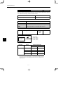
1.1 Checking Products on Delivery
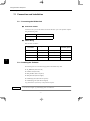
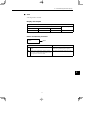
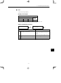
The following procedure is used to check products upon delivery. Check the following items when
products are delivered.
1
Check Items
Comments
Are the delivered products the ones
that were ordered?
Check the model numbers marked on the nameplates
of the NS500 Unit. (Refer to the descriptions of model
numbers on following pages)
Is there any damage?
Check the overall appearance, and check for damage
or scratches that may have occurred during shipping.
Can the NS500 Unit be installed on
the SERVOPACK used?
Check the model number given on the SERVOPACK
nameplate. The model number must contain “SGDH”
and “E” as shown below to support the NS500 Unit.
SGDH-jjjE-j
If any of the above items are faulty or incorrect, contact your Yaskawa sales representative or the dealer from whom you purchased the products.
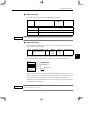
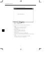
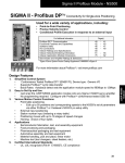
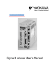
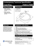
J External Appearance and Nameplate Example
Option unit type
Option unit name
SERVOPACK
PROFIBUS-DP I/F UNIT
MODEL JUSP-NS500
VER. 000000
S/N V81003-69
YASKAWA ELECTRIC
MADE IN JAPAN
Serial number
NS500 Unit
1 -2
Version number
1.1 Checking Products on Delivery
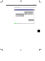
J Model Number
NS500 Unit
JUSP − NS50 0
SERVOPACK Peripheral Device
Type of device:
NS50: PROFIBUS-DP Interface Unit
1 -3
Design Revision Order
1
Checking Products and Part Names
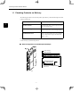
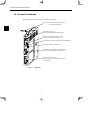
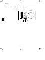
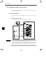
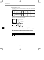
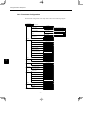
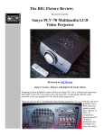
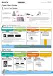
1.2 Product Part Names
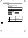
The following diagram illustrates the part names of the NS500 Unit.
Ground wire: Connected to the terminal marked “G”
on the SGDH SERVOPACK.
1
Rotary switches (X1, X10):
Used to set the PROFIBUS-DP station address.
RS-232C Communications Connector (CN11):
Used to communicate with the Setup Tool.
LED (COMM): Communication Status LED for PROFIBUS-DP
LED (ERR): Module Error Status LED
PROFIBUS-DP Communications Connector (CN6):
Connector for PROFIBUS-DP Communications.
External I/O Connector (CN4):
Connector for external I/O signals and fully closed
encoder signals.
Figure 1.1
NS500 Unit
1 -4
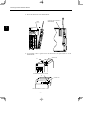
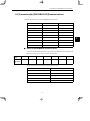
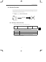
1.3 Mounting the NS500 Unit
1.3 Mounting the NS500 Unit
This section describes how to mount a NS500 Unit on the SGDH SERVOPACK.
Prepare the screws for connecting the ground wire as shown in the following table:
Mounting Type
Base Mounted
SERVOPACK Models
SGDH-A3 to 02BE
Remarks
M3 × 10 round-head screw
(spring or flat washer)
Attachments
M4 × 10 round-head screws
(spring or flat washer)
Attachments
SGDH-60/75AE
M4 × 8 round-head screw
(spring or flat washer)
Use front panel fixer screws
SGDH-A3 to 02BE-R
M4 × 6 round-head screws
(spring or flat washer)
Attachments
M4 × 8 round-head screw
(spring or flat washer)
Use front panel fixer screws
SGDH-A3 to 10AE
SGDH-15 to 50AE
SGDH-05 to 30DE
Rack Mounted
Screw
SGDH-A3 to 50AE-R
SGDH-05 to 30DE-R
Duct Vent
SGDH-60/75AE-P
Note: Be sure to use spring washers or flat washers. Failure to do so may result in the screws for
connecting the ground wire protruding behind the flange, preventing the SERVOPACK
from being mounted.
By mounting NS500 Unit, the SGDH SERVOPACK can be used in a DeviceNet network. Use the
following procedure to ensure NS500 Units are mounted correctly.
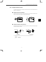
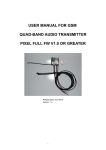
1. Remove the connector cover from the CN10 connector on the SERVOPACK.
CN10
YASKAWA SERVOPACK
SGDH-
Connector cover
MODE/SET
DATA/
CHARGE
1 -5
POWER
1
Checking Products and Part Names
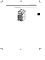
2. Mount the NS500 Unit on the SERVOPACK.
Connector (for connection to
SERVOPACK)
CN10
YASKAWA SERVOPACK
SGDHNS5 0 0
Ver.
8
CHARGE POWER
6
1
L1
L2
1
2
L1C
L2C
B1
B2
U
V
W
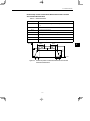
3. For grounding, connect a ground wire of the NS500 Unit to the point marked “G” on the
SERVOPACK.
Ground wire
“G”
YASKAWA SERVOPACK
SGDH-
MODE/SET
CHARGE
NS500
DATA/
POWER
For SERVOPACK 30 W to 5.0 kW
“G”
Ground wire
YASKAWA
SERVOPACK 200V
SGDH -
NS100
For SERVOPACK 6.0 kW to 7.5 kW
1 -6
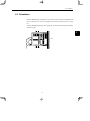
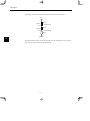
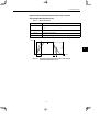
1.3 Mounting the NS500 Unit
When the NS500 Unit has been mounted correctly, the SERVOPACK will appear as shown
in the following diagram.
1
1 -7
2
Installation
This chapter describes precautions for Σ-II Series product installation.
The SGDH SERVOPACKs are base-mounted servo amplifiers. Incorrect
installation will cause problems. Always observe the installation precautions shown in this chapter.
2.1
2.2
2.3
2.4
Storage Conditions . . . . . . . . . . . . . . . . . . . .
Installation Site . . . . . . . . . . . . . . . . . . . . . . . .
Orientation . . . . . . . . . . . . . . . . . . . . . . . . . . .
Installation . . . . . . . . . . . . . . . . . . . . . . . . . . . .
2 -1
2 -2
2 -2
2 -3
2 -4
2
Installation
2.1 Storage Conditions
Store the SERVOPACK within the following temperature range when it is stored with the power
cable disconnected.
Temperature range: −20 to 85°C
2
Σ-II Series SGDH SERVOPACK
with NS500 Unit mounted
2.2 Installation Site
Take the following precautions at the installation site.
Situation
Installation Precaution
Installation in a Control
Panel
Design the control panel size, unit layout, and cooling method so that
the temperature around the SERVOPACK does not exceed 55°C.
Installation Near a
Heating Unit
Minimize heat radiated from the heating unit as well as any temperature rise caused by natural convection so that the temperature around
the SERVOPACK does not exceed 55°C.
Installation Near a
Source of Vibration
Install a vibration isolator beneath the SERVOPACK to avoid subjecting it to vibration.
Installation at a Site
Exposed to Corrosive
Gas
Corrosive gas does not have an immediate effect on the SERVOPACK, but will eventually cause electronic components and contactor-related devices to malfunction. Take appropriate action to avoid
corrosive gas.
Other Situations
Do not install the SERVOPACK in hot or humid locations, or locations subject to excessive dust or iron powder in the air.
2 -2
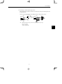
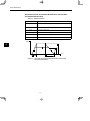
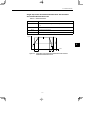
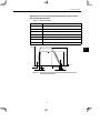
2.3 Orientation
2.3 Orientation
Install the SERVOPACK perpendicular to the wall as shown in the figure. The SERVOPACK
must be oriented this way because it is designed to be cooled by natural convection or cooling
fan.
Secure the SERVOPACK using 2 to 4 mounting holes. The number of holes depends on the SERVOPACK capacity.
2
Wall
MADE IN JAPAN
Ventilation
2 -3
Installation
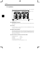
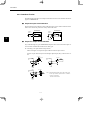
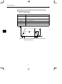
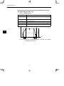
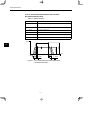
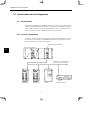
2.4 Installation
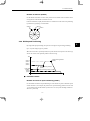
Follow the procedure below to install multiple SERVOPACKs side by side in a control panel.
FAN
FAN
NS500
NS500
NS500
50mm (2in.) or more
NS500
2
10mm (0.4in.) or more
50mm (2in.) or more
30mm (1.2in.) or more
J SERVOPACK Orientation
Install the SERVOPACK perpendicular to the wall so that the front panel (containing connectors)
faces outward.
J Cooling
As shown in the figure above, provide sufficient space around each SERVOPACK for cooling
by cooling fans or natural convection.
J Side-by-side Installation
When installing SERVOPACKs side by side as shown in the figure above, provide at least 10 mm
(0.39 in) between and at least 50 mm (1.97 in) above and below each SERVOPACK. Install cooling fans above the SERVOPACKs to avoid excessive temperature rise and to maintain even temperature inside the control panel.
J Environmental Conditions in the Control Panel
D Ambient Temperature:
0 to 55°C
D Humidity:
90% or less
D Vibration:
4.9 m/s2
D Condensation and Freezing: None
D Ambient Temperature for Long-term Reliability: 45°C max.
2 -4
3
Connectors
This chapter describes the procedure used to connect Σ-II Series products
to peripheral devices when NS500 Unit is mounted and gives typical examples of I/O signal connections.
3.1 Connecting to Peripheral Devices . . . . . . .
3.1.1 Single-phase (100 V or 200 V)
Main Circuit Specifications . . . . . . . . . . . . . . . . . . .
3.1.2 Three-phase, 200-V Main Circuit Specifications . .
3.1.3 Three-phase, 400-V Main Circuit Specifications . .
3.2 SERVOPACK Internal Block Diagrams . . .
3.3 I/O Signals . . . . . . . . . . . . . . . . . . . . . . . . . . .
3.3.1 Connection Example
of I/O Signal Connector (CN1) . . . . . . . . . . . . . . . .
3.3.2 I/O Signals Connector (CN1) . . . . . . . . . . . . . . . . . .
3.3.3 I/O Signal Names and Functions . . . . . . . . . . . . . .
3.3.4 Interface Circuits . . . . . . . . . . . . . . . . . . . . . . . . . . . .
3.4 I/O Signal Connections
for NS500 Units (CN4) . . . . . . . . . . . . . . . .
3.4.1 Connection Terminal Layout . . . . . . . . . . . . . . . . . .
3.4.2 I/O Signal Interface Circuits . . . . . . . . . . . . . . . . . . .
3.4.3 Fully-closed Encoder Connection Example . . . . . .
3.5 Connectors for PROFIBUS-DP
Communications . . . . . . . . . . . . . . . . . . . . . .
3 -1
3 -2
3 -3
3 -4
3 -5
3 -6
3 -7
3 -7
3 -8
3 -9
3 -10
3 -12
3 -12
3 -13
3 -14
3 -15
3
Connectors
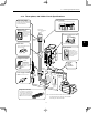
3.1 Connecting to Peripheral Devices
This section provides examples of standard Σ-II Series product connections to peripheral devices.
It also briefly explains how to connect each peripheral device.
3
3 -2
3.1 Connecting to Peripheral Devices
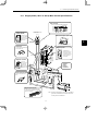
3.1.1 Single-phase (100 V or 200 V) Main Circuit Specifications
Host Controller
Can be connected to PROFIBUS-DP Master.
Power supply
Single-phase 200 VAC
Molded-case Circuit
Breaker (MCCB)
R S T
Personal Computer (See note.)
Protects the power line by shutting
the circuit OFF
when overcurrent
is detected.
3
Molded-case
circuit breaker
Cable model: JZSP-CMS01 to 03
Noise Filter
Used to eliminate external noise
from the power line.
Digital Operator
JUSP-OP02A-2
Allows the user to set
parameters or operation references and to
display operation or
alarm status.
Noise filter
Magnetic Contactor
HI Series
Turns the servo
ON and OFF.
Install a surge
suppressor on the
magnetic contactor.
Magnetic
contactor
Power Supply for Brake
Used for a servomotor with a
brake.
Encoder
Cable
Encoder
Connector
Magnetic
contactor
Power
supply
ground
line
Brake
power
supply
U V W
L1 L2 L1C L2C
B1 B2
Regenerative
resistor
(option)
Regenerative Resistor
Connect an external regenerative resistor
to terminals B1 and B2 if the regenerative
capacity is insufficient.
Note Used for maintenance. Be sure to coordinate
operation from these devices with controls exerted by the host controller.
3 -3
Connectors
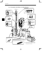
3.1.2 Three-phase, 200-V Main Circuit Specifications
3.1.2 Three-phase, 200-V Main Circuit Specifications
Molded-case Circuit
Breaker (MCCB)
Protects the power line by shutting
the circuit OFF
when overcurrent
is detected.
Host Controller
Power supply
Three-phase 200 VAC
R S T
Can be connected to PROFIBUS-DP Master.
Molded-case
circuit breaker
Personal Computer (See note.)
Noise Filter
Used to eliminate external noise
from the power line.
Cable model: JZSP-CMS01 to 03
3
Digital Operator
Noise filter
JUSP-OP02A-2
Magnetic Contactor
Allows the user to set
parameters or operation references and to
display operation or
alarm status.
HI Series
Turns the servo
ON and OFF.
Install a surge
suppressor on the
magnetic contactor.
Encoder
Cable
Encoder
Connector
Magnetic
contactor
Magnetic
contactor Power
supply
ground
line
Brake
power
supply
U V W
L1 L2 L3
L1C L2C
B1 B2
Regenerative
resistor
(option)
Power Supply for Brake
Used for a servomotor with a
brake.
Regenerative Resistor
If the capacity of the internal regenerative resistor is insufficient,
remove the wire between terminals B2 and B3 and connect an
external regenerative resistor to terminals B1 and B2.
Note Used for maintenance. Be sure to coordinate
operation from these devices with controls
exerted by the host controller.
3 -4
3.1 Connecting to Peripheral Devices
3.1.3 Three-phase, 400-V Main Circuit Specifications
Host Controller
Brake Power Supply
Can be connected to PROFIBUS-DP Master.
100-VAC or 200-VAC power supply.
24-VDC power supply for servomotors with 24-VDC brakes.
Power supply
Three-phase 400 VAC
R S T
Molded-case Circuit
Breaker (MCCB)
Protects the power line by shutting
the circuit OFF
when overcurrent
is detected.
Personal Computer (See note.)
Moldedcase circuit
breaker
Noise Filter
Cable model: JZSP-CMS01 to 03
Used to eliminate external noise
from the power line.
Digital Operator
JUSP-OP02A-2
Allows the user to set
parameters or operation references and to
display operation or
alarm status.
Noise filter
Magnetic Contactor
HI Series
Turns the servo
ON and OFF.
Install a surge
suppressor on the
magnetic contactor.
Magnetic
contactor
Power Supply for Brake
Used for a servomotor with a
brake.
Brake
power
supply
Encoder
Cable
Encoder
Connector
Magnetic
contactor Power
supply
ground
line
U V W
L1 L2 L3
24V 0V
B1 B2
DC power supply
(24V)
Regenerative
resistor
(option)
Regenerative Resistor
If the capacity of the internal regenerative resistor is insufficient, remove
the wire between terminals B2 and
B3 and connect an external regenerative resistor to terminals B1 and
B2.
Note Used for maintenance. Be sure to coordinate
operation from these devices with controls
exerted by the host controller.
3 -5
3
Connectors
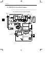
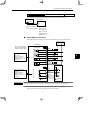
3.2 SERVOPACK Internal Block Diagrams
The following sections show an internal block diagram for the SERVOPACK with the NS500 Unit.
30 to 400 W 200-V and 30 to 200 W 100-V Models
Single-phase +10 %
200 to 230 V
−15%
(50/60Hz)
B1
Noise
filter
3
THS1
RY1
2
D2D3D4
PM1-1
P1
FU1
1MC
B2
1
L1
P2
V
−
T
L2
Voltage
sensor
Gate
drive
Voltage
sensor
~
~
V
R8
W
N2
Relay
drive
L2C
W
TR1
N1
L1C
U
U
+
C1
AC servomotor
R7
D1
CHARGE
R
PM1-2
Gate drive overcurrent protector
CN2
PG
Interface
+
−
−
DC/DC
converter
For battery
connection
Current
sensor
±5V
+15V
+
CN8
ASIC
(PWM control)
+5V
±12V
CN1
+5V
Power Power
OFF ON
Monitor display
1MC
CPU
(position and speed
calculation)
0V
1MC
Surge
suppressor
POWER
Analog voltage
converter
CN5
Open during
(5Ry) servo alam
Monitor output
for supervision
I/O
CN3
Sequence I/O
CN10
Digital Operator/
personal computer
CN10
CN6
Master node
24-V communications
power supply
Bus interface
PROFIBUS-DP
communications
interface
CN4
CPU
(position commands,
command interpretation,
arithmetic processing,
etc.)
+5V
R
+5V
3 -6
Power supply
SW1, SW2
Station No.
SW3
A
Fully-closed PG
Baud rate
3.3 I/O Signals
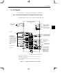
3.3 I/O Signals
This section describes I/O signals for the SERVOPACK with the NS500 Unit.
3.3.1 Connection Example of I/O Signal Connector (CN1)
The following diagram shows a typical example of I/O signal connections.
+
−
BAT+
21
BAT−
22
SGDH SERVOPACK
CN1
37
ALO1
38
ALO2
39
1
ALO3
SG
40
25
/COIN+ Positioning completed
/DEC
41
26
/COIN− has been completed)
P-OT
42
27
/BK+
Reverse run prohibited
(Prohibited when OFF)
N-OT
43
28
/BK−
External positioning
signal
EXTP
44
29
/S-RDY+
30
/S-RDY− (ON when ready)
31
ALM+
32
ALM− (OFF for an alarm)
Backup battery
2.8 to 4.5 V*2
Not used
+24VIN
+24V
47
Alarm code output
Maximum operating
voltage: 30 VDC
Maximum operating
current: 20 mA DC
3.3KΩ
+
−
Zero point return
deceleration LS
(LS enabled when ON)
Forward run prohibited
(Prohibited when OFF)
ZERO
Zero point signal
45
Connector shell
FG
Connect the shield wire to connector shell.
* 1.
represents twisted-pair wires.
* 2. When using an absolute encoder, connect a backup battery only when there is no
battery connected to the CN8.
* 3. Make signal allocations using parameters. (Refer to 6.1.2 Standard Settings for
CN1 I/O Signals.)
Figure 3.1
Brake output *3
(ON when brake
released)
Servo ready output
Servo alarm output
46
Not used
(ON when positioning
I/O Signal Connections for CN1 Connectors
3 -7
Photocoupler output
Maximum operating
voltage: 30 VDC
Maximum operating
current: 50 mA DC
3
Connectors
3.3.2 I/O Signals Connector (CN1)
3.3.2 I/O Signals Connector (CN1)
The following diagram shows the layout of CN1 terminals.
J CN1 Terminal Layout
1
2
SG
27
−
3
SG
8
−
29 /S-RDY+
−
−
−
9
−
−
11
−
−
−
−
−
−
−
−
−
−
37 ALO1
Alarm code
output
t t
39 ALO3
( p
(open-collector output)
41 /DEC
Zero ppoint return deceleration LS input
−
Battery (+)
Battery (−)
( )
47 +24VIN
23
24
−
45 ZERO
21 BAT (+)
22 BAT (−)
( )
35
43 N-OT
−
−
−
25 /COIN +
−
Positioning
complete
l
output
Servo alarm
output
−
−
−
Servo ready
y
output
−
−
−
19
20
−
49
26 /COIN−
Positioning
complete
output
/BK
/BK−
(Note 3)
Brake interinter
lock output
Brake interlock output
33
−
−
17
18
−
−
15
16
−
7
13
14
−
31 ALM+
GND
−
/BK+
(Note 3)
−
GND
10 SG
12
−
−
5
6
GND
GND
3
4
SG
Reverse run
prohibited
input
Zero ppoint
signal
External
power supply
input
−
28
30 /S-RDY−
/S RDY
Servo ready
output
32 ALM−
Servo alarm
output
34
−
−
36
−
−
38 ALO2
40
−
Alarm code
output
−
42 P-OT
Forward drive
prohibited
input
44 EXTP
External ppositioning signal
46
−
−
48
−
−
50
−
−
−
Note 1. Do not use unused terminals for relays.
2. Connect the shield of the I/O signal cable to the connector shell.
The shield is connected to the FG (frame ground) at the SERVOPACK-end connector.
3. Make signal allocations using parameters. (Refer to 6.1.2 Standard Settings for CN1 I/O Signals.)
J CN1 Specifications
Specifications for
SERVOPACK
Connectors
10250-52A2JL 50-p
Right Angle Plug
Applicable Receptacles
Soldered
10150-3000VE
3 -8
Case
10350-52A0-008
Manufacturer
Sumitomo 3M Ltd.
3.3 I/O Signals
3.3.3 I/O Signal Names and Functions
The following section describes SERVOPACK I/O signal names and functions.
J Input Signals
Signal Name
Pin No.
Function
Common /DEC
41
P-OT
N-OT
EXTP
42
43
44
ZERO
+24VIN
45
47
Zero point return deceleration NS:
Deceleration LS for zero point return connected.
Forward run prohibited Overtravel prohibited: Stops servomotor when movable part travels
Reverse run prohibited
beyond the allowable range of motion.
External positioning signal:
Signal used for external positioning connected.
Zero point
Control power supply input for sequence signals: Users must provide the +24-V power supply.
BAT (+)
BAT (−)
21
22
Allowable voltage fluctuation range: 11 to 25 V
Connecting pin for the absolute encoder backup battery.
Connect to either CN8 or CN1.
J Output Signals
Signal Name
Common
Position
Pin No.
Function
ALM+
ALM−
31
32
Servo alarm: Turns OFF when an error is detected.
/BK+
/BK−
27
28
Brake interlock: Output that controls the brake. The brake is released when this signal is ON.
/S-RDY+
/S-RDY−
29
30
Servo ready: Turns ON if there is no servo alarm when the control/main circuit power supply is turned ON.
ALO1
ALO2
ALO3
37
38
39 (1)
Alarm code output: Outputs 3-bit alarm codes.
Open-collector: 30 V and 20 mA rating maximum
FG
Shell
Connected to frame ground if the shield wire of the I/O signal cable is connected to the connector shell.
/COIN+
/COIN−
25
26
Positioning completed (output in Position Control Mode): Turns ON when the number of
error pulses reaches the set value. The setting is the number of error pulses set in reference
units (input pulse units defined by the electronic gear).
Note 1. Pin numbers in parenthesis () indicate signal grounds.
2. The functions allocated to /BK, /S-RDY, and /COIN can be changed via parameters. The /BK, /S-RDY, and /COIN output
signals can be changed to /CLT, /VLT, /TGON, /WARN, or /NEAR signals.
3 -9
3
Connectors
3.3.4 Interface Circuits
3.3.4 Interface Circuits
The following diagram shows an example of connections between a host controller and the I/O
signal for a SERVOPACK.
J Sequence Input Circuit Interface
The sequence input circuit interface connects through a relay or open-collector transistor circuit.
Select a low-current relay, otherwise a faulty contact will result.
SERVOPACK
24 VDC
50 mA min.
SERVOPACK
24 VDC
50 mA min.
+24VIN 3.3k Ω
/DEC,etc.
+24VIN 3.3k Ω
/DEC,etc.
3
J Sequence Output Circuit Interface
Any of the following two types of SERVOPACK output circuits can be used. Form an input circuit at the host controller that matches one of these types.
D Connecting to an Open-collector Output Circuit
Alarm code signals are output from open-collector transistor output circuits.
Connect an open-collector output circuit through a photocoupler, relay, or line receiver circuit.
5 to 12 VDC
photocoupler
SERVOPACK
end
0V
5 to 24 VDC
Relay
SERVOPACK
end
0V
0V
0V
5 to 12 VDC
SERVOPACK
end
0V
0V
3 -10
Note The maximum allowable voltage and current capacities for open-collector output circuits are as follows:
· Voltage: 30 VDC max.
· Current: 20 mA DC max.
3.3 I/O Signals
D Connecting to a Photocoupler Output Circuit
Photocoupler output circuits are used for servo alarm, servo ready, and other sequence output signal circuits.
Connect a photocoupler output circuit through a relay or line receiver circuit.
5 to 24 VDC
SERVOPACK
end
0V
5 to 12 VDC
Relay
SERVOPACK
end
0V
0V
0V
Note The maximum allowable voltage and current capacities for photocoupler output
circuits are as follows:
· Voltage: 30 VDC max.
· Current: 50 mA DC max.
3 -11
3
Connectors
3.4.1 Connection Terminal Layout
3.4 I/O Signal Connections for NS500 Units (CN4)
The CN4 on an NS500 Unit is used for I/O signal and fully-closed encoder signal connections.
3.4.1 Connection Terminal Layout
The terminal layout and specifications for the CN4 are outlined below.
J CN4 Terminal Layout
Pin No.
3
Signal
Description
Pin No.
Signal
Description
1
PG 0V
Signal ground
11
+24VIN
24-V common terminal
for external input
2
PG 0V
Signal ground
12
NOTCH1+
Notch output 1
3
PG 0V
Signal ground
13
NOTCH1−
−
4
−
−
14
PC
Phase-C input
5
−
−
15
/PC
−
6
−
−
16
PA
Phase-A input
7
−
−
17
/PA
−
8
−
−
18
PB
Phase-B input
9
EMSTOP
Emergency stop input
19
/PB
−
10
NOTCH2+
Notch output 2
20
NOTCH2−
Notch output 2
Note 1. The PG power supply and battery must be supplied externally.
2. The FG is connected to the connector shell.
J Connector Specifications
Part
Signal
Manufacturer
Connector
10120-3000VE (20P)
Sumitomo 3M Ltd.
Connector shell
10320-52A0-008
−
3 -12
3.4 I/O Signal Connections for NS500 Units (CN4)
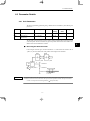
3.4.2 I/O Signal Interface Circuits
The following diagram shows an example of connections between a host controller and the I/O
signals for an NS500 Unit.
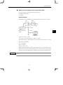
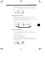
J Sequence I/O Circuit Interface
The sequence input circuit interface connects through a relay or open-collector transistor circuit.
Select a low-current relay, otherwise a faulty contact will result.
NS500
NS500
24 VDC
50 mA min.
24 VDC
50 mA min.
+24VIN 3.3kΩ
+24VIN 3.3k Ω
EMSTOP
EMSTOP
3
Open Collector
Relay
J Sequence Output Circuit Interface
Notch output signals are used for photocoupler output circuits. Connect the notch output signals
to relays or line receiver circuits.
5 to 12 VDC
5 to 24 VDC
NS500 end
Relay
NS500 end
0V
0V
0V
0V
Line Receiver
Relay
Note The maximum allowable voltage and current capacity for photocoupler output circuits are
as follows:
⋅ Voltage: 30 VDC max.
⋅ Current: 50 mA DC max.
3 -13
Connectors
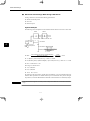
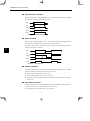
3.4.3 Fully−closed Encoder Connection Example
3.4.3 Fully-closed Encoder Connection Example
The following diagram shows a connection example for a fully-closed encoder.
NS500
PG0V
External PG
CN4
1,2,3
PA
16
/PA
17
GND
A
/A
18
B
/PB
19
/B
PC
14
Z
/PC
15
PB
/Z
3
External
power
supply
3 -14
: Shield.
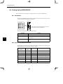
3.5 Connectors for PROFIBUS-DP Communications
3.5 Connectors for PROFIBUS-DP Communications
SUB-D 9-pin connectors are used for PROFIBUS-DP connections.
Pin number
Symbol
Function
1
−
−
2
−
−
3
RXD/TXD-P
Receive/send data, positive
4
−
−
5
DGND
Ground
6
VP
+5 V
7
−
−
8
RXD/TXD-N
Receive/send data, negative
9
−
−
3
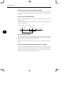
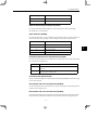
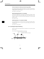
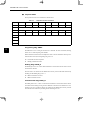
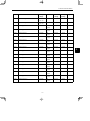
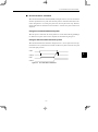
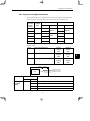
J Cables for PROFIBUS-DP Communications
Use commercial PROFIBUS-DP cables. Type A cables are recommended. The maximum cable
lengths when using type A cables are given in the table below.
Baud rate
(kbps)
9.6
1200
Maximum
cable length
(m)
19.2
93.75
187.5
500
1500
1200
1200
1200
1000
400
200
100
The specifications for type A cables are given in the table below.
Item
Specifications
Impedance
135 to 165 Ω
Capacitance per Unit
< 30 pF/m
Loop resistance
110 Ω/m
Core diameter
0.64 mm
Core cross-sectional area
> 0.34 mm2
3 -15
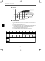
Connectors
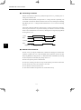
Terminating resistances are required at both ends of the bus line as shown below.
VP (6)
Data line
390 Ω
RXD/TXD-P (3)
Data line
220 Ω
RXD/TXD-N (8)
390 Ω
3
DGND (5)
The NS500 Unit does not have terminating resistance. Use the terminating resistance in the bus
plug connector on the cable side for the NS500 Unit.
3 -16
4
Parameter Settings
This chapter provides an outline and details of NS500 parameters.
4.1 Parameters . . . . . . . . . . . . . . . . . . . . . . . . . . .
4 -2
4.1.1 Outline of Parameters . . . . . . . . . . . . . . . . . . . . . . . .
4 -2
4.1.2 Parameter Types . . . . . . . . . . . . . . . . . . . . . . . . . . . .
4 -2
4.1.3 Editing Parameters . . . . . . . . . . . . . . . . . . . . . . . . . .
4 -3
4.1.4 Effective Timing . . . . . . . . . . . . . . . . . . . . . . . . . . . . .
4 -3
4.2 Parameter Tables . . . . . . . . . . . . . . . . . . . . . .
4 -4
4.2.1 Unit Parameters . . . . . . . . . . . . . . . . . . . . . . . . . . . . .
4 -4
4.2.2 Zero Point Return Parameters . . . . . . . . . . . . . . . . .
4 -4
4.2.3 Machine System and
Peripheral Device Parameters . . . . . . . . . . . . . . .
4 -5
4.2.4 Speed, Acceleration, and Deceleration Parameters
4 -6
4.2.5 Positioning Parameters . . . . . . . . . . . . . . . . . . . . . . .
4 -8
4.2.6 Multi-speed Positioning Parameters . . . . . . . . . . . .
4 -9
4.2.7 Notch Output Parameters . . . . . . . . . . . . . . . . . . . . .
4 -10
4.3 Parameter Details . . . . . . . . . . . . . . . . . . . . .
4 -11
4.3.1 Unit Parameters . . . . . . . . . . . . . . . . . . . . . . . . . . . . .
4 -11
4.3.2 Zero Point Return Parameters . . . . . . . . . . . . . . . . .
4 -14
4.3.3 Machine System and Peripheral Devices . . . . . . .
4 -19
4.3.4 Speed, Acceleration, and Deceleration . . . . . . . . .
4 -21
4.3.5 Positioning Parameters . . . . . . . . . . . . . . . . . . . . . . .
4 -33
4.3.6 Multi-speed Positioning . . . . . . . . . . . . . . . . . . . . . .
4 -35
4.3.7 Notch Signal Output Positioning . . . . . . . . . . . . . . .
4 -36
4 -1
4
Parameter Settings
4.1.2 Parameter Types
4.1 Parameters
4.1.1 Outline of Parameters
Parameters is the name given to the user constants that are required as the settings used to operate the NS500 Unit. You must set the optimum values for parameters according to the NS500
Unit and the machine to which the SGDH is mounted.
You can edit the NS500 Unit parameters using the NSxxx Setup Tool or host controller.
For parameters, refer to Chapter 6 Parameter Settings or the Σ-II Series SGMjH/SGDH User’s
Manual Design and Maintenance (SIE-S800-32.2).
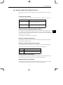
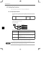
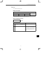
4.1.2 Parameter Types
4
Parameters are classified depending on their purpose as follows:
D Unit parameters
D Zero Point Return parameters
D Machine system and peripheral device parameters
D Speed, acceleration, and deceleration parameters
D Positioning parameters
D Multi-speed positioning parameters
D Notch output positioning parameters
Parameters are further classified according to the priority of the setting, as shown below.
Table 4.1
Parameter Types
Type
Meaning
A
Parameters that must be set even when using the NS500 Unit in standard mode.
B
Parameters that must be set when using the NS500 Unit in special mode.
C
Parameters whose settings hardly ever need to be changed.
4 -2
4.1 Parameters
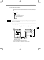
4.1.3 Editing Parameters
You can edit parameters using the following methods.
Table 4.2
Methods of Editing Parameters
Methods
Remarks
NSxxx Setup
Tool
Select Option Parameter List from the
Parameter Menu to read all the NS500
Unit parameters. After the parameters
have been displayed, select the parameters you want to edit, and click the Edit
Button to edit the parameters.
All changed parameters are stored in
RAM, so they are erased when the
power is turned OFF. Use the Module
Reset Command to write the parameter
data in RAM to the flash ROM.
Master Device
You can edit using 8-bytes commands
from the Master Device.
All changed parameters are stored in
RAM, so they are erased when the
power is turned OFF. Execute the Reset
Service for the Identity Object to write
the parameter data in RAM to the flash
ROM.
Tools
IMPORTANT
Parameters changed from each setting device are stored in RAM.
To save parameters in flash ROM after adjustments have been completed, execute the Module Reset Command
in the NSxxx Setup Tool or execute the Reset Service to the Identity Object via DeviceNet.
4.1.4 Effective Timing
Not all parameters edited from the NSxxx Setup Tool or Master Device are effective immediately. Changed parameters are effective at one of the following two times.
Table 4.3
Effective Timing for Parameters
Timing
Power-up
Control or Processing
The values of all parameters are made effective at the following times.
1. When power is turned ON.
2. When the Module is reset from the NSxxx Setup Tool or via a command data.
Immediate
The values of changed parameters are made effective immediately.
However, parameters will be stored in the Flash ROM at the following times.
S When the Module is reset from the NSxxx Setup Tool or via a command data.
4 -3
4
Parameter Settings
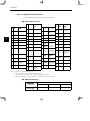
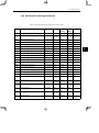
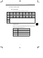
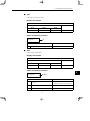
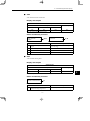
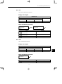
4.2.2 Zero Point Return Parameters
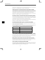
4.2 Parameter Tables
The following tables list the parameters.
If using the NSxxx Setup Tool or reading/writing using a command data, edit parameters using
Pnjjj.
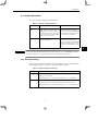
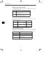
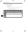
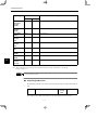
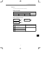
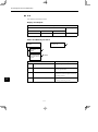
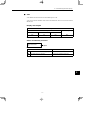
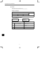
4.2.1 Unit Parameters
The unit parameter table is shown below.
No.
Name
Range
Units
Effective
Timing
Default
Value
Type
Pn810
Electronic Gear Ratio
(Numerator)
1 to 10,000,000
−
Power-up
1
B
Pn811
Electronic Gear Ratio
(Denominator)
1 to 10,000,000
−
Power-up
1
B
4
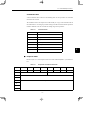
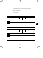
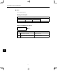
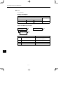
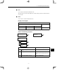
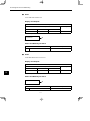
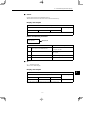
4.2.2 Zero Point Return Parameters
The table of zero point return parameters are shown below.
No.
Name
Range
Units
Effective
Timing
Default
Value
Type
Pn800
Zero Point Return Mode
0 to 3
−
Immediate
0
B
Pn801
Zero Point Return Function
Selection
0 to 7
−
Power-up
1
B
Pn802
Feed Speed for Zero Point
Return
1 to 240,000
1000 steps/
min
Immediate
10,000
B
Pn803
Approach Speed for Zero
Point Return
1 to 240,000
1000 steps/
min
Immediate
1,000
B
Pn804
Creep Speed for Zero Point
Return
1 to 240,000
1000 steps/
min
Immediate
500
B
Pn805
Final Travel Distance for
Zero Point Return
0 to 99,999,999
Steps
Immediate
0
B
Pn806
Output Width for Zero Point
Return
0 to 32, 767
Steps
Immediate
100
B
Pn809
Zero Point Offset
−99,999,999 to
99,999,999
Steps
Immediate
0
C
Pn80A
Accel/Decel Time for Zero
Point Return
1 to 10,000
ms
Immediate
100
B
Note: 1. “Steps” means “reference unit.” For reference unit details, refer to 4.3.1 Unit Parameters.
2. If you set the reference unit to 0.001 mm, 1,000 steps/min becomes mm/min.
4 -4
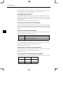
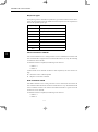
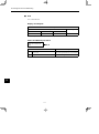
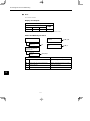
4.2 Parameter Tables
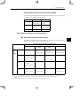
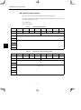
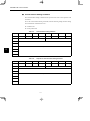
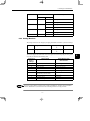
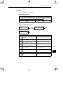
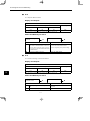
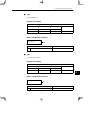
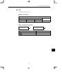
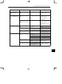
4.2.3 Machine System and Peripheral Device Parameters
The machine system and peripheral device parameter table is shown below.
No.
Name
Pn812
Coordinate Type
Pn813
Range
Units
0, 1
Effective
Timing
Default
Value
Type
−
Immediate
0
C
Reference units per Machine 1 to 1,500,000
Rotation
−
Immediate
360,000
C
Pn814
Backlash Compensation
0 to 32,767
Steps
Immediate
0
C
Pn815
Backlash Direction
0, 1
Steps
Immediate
0
C
Pn816
Positive Software Limit
±99,999,999
−
Power-up
99999999
B
Pn817
Negative Software Limit
±99,999,999
Steps
Power-up
−99999999
B
Pn818
Machine Function Selection
0 to 3
−
Immediate
0
B
Pn819
Hardware Limit Signal
Function Selection
0 to 3
−
Immediate
1
B
Pn81A
Hardware Limit Action
Selection
0, 1, 2
−
Immediate
0
B
Pn81B
Emergency Stop Signal
Function Selection
0 to 3
−
Immediate
1
B
Note: 1. “Steps” means “reference unit.” For reference unit details, refer to 4.3.1 Unit Parameters.
2. If you set the reference unit to 0.001 mm, 1,000 steps/min becomes mm/min.
4 -5
4
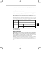
Parameter Settings
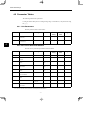
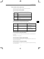
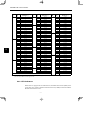
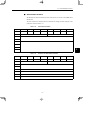
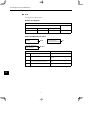
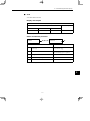
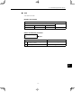
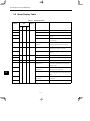
4.2.4 Speed, Acceleration, and Deceleration Parameters
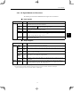
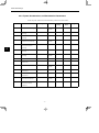
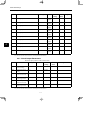
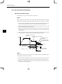
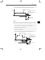
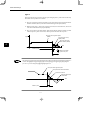
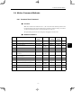
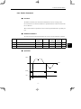
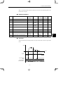
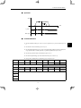
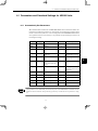
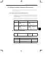
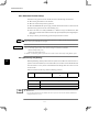
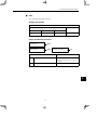
4.2.4 Speed, Acceleration, and Deceleration Parameters
A table of speed, acceleration, and deceleration parameters is shown below.
No.
4
Name
Range
Units
Effective
Timing
Default
Value
Type
Pn821
Feed Speed for Positioning
1 to 240,000
1000
steps/min
Immediate
24,000
B
Pn822
Acceleration Time for
Positioning
1 to 10,000
ms
Immediate
100
B
Pn823
Deceleration Time for
Positioning
1 to 10,000
ms
Immediate
100
C
Pn824
Switch Speed for Second
Accel/Decel for Positioning
1 to 240,000
1000
steps/min
Immediate
24,000
C
Pn825
Accel/Decel Time for
Second Accel/Decel for
Positioning
1 to 10,000
ms
Immediate
200
B
Pn826
Accel/Decel Type for
Positioning
0 to 3
−
Immediate
0
B
Pn827
Feed Speed for External
Positioning
1 to 240,000
1000
steps/min
Immediate
24,000
B
Pn829
Filter Selection
0 to 3
−
Immediate
0
B
Pn830
Constant Feed Reference
Unit Selection
0, 1
−
Immediate
0
B
Pn831
Constant Feed Speed
1 to 240,000
1000
steps/min
Immediate
24,000
B
Pn832
Acceleration Time for
Constant Feed
1 to 10,000
ms
Immediate
100
B
Pn833
Deceleration Time for
Constant Feed
1 to 10,000
ms
Immediate
100
C
Pn834
Switch Speed for Constant
Feed Second Accel/Decel
1 to 240,000
1000
steps/min
Immediate
24,000
C
Pn835
Accel/Decel Time for
Constant Feed Second
Accel/Decel
1 to 10,000
ms
Immediate
200
C
4 -6
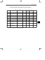
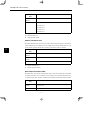
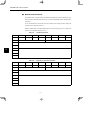
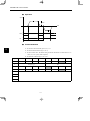
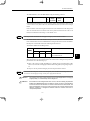
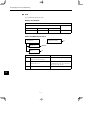
4.2 Parameter Tables
No.
Name
Range
Units
Effective
Timing
Default
Value
Type
Pn836
Accel/Decel Type for
Constant Feed
0, 1, 2, 3
−
Immediate
0
B
Pn840
Time Constant for
Exponential Accel/Decel
4 to 10,000
ms
Immediate
25
C
Pn841
Bias Speed for Exponential
Accel/Decel
1 to 240,000
1000
steps/min
Immediate
0
C
Pn842
Time Constant of Travelling
Average
4 to 10,000
ms
Immediate
25
C
Pn843
Maximum Feed Speed
1 to 240,000
1000
steps/min
Immediate
24,000
B
Pn844
Step Distance 1
0 to 99,999,999
Steps
Immediate
1
B
Pn845
Step Distance 2
0 to 99,999,999
Steps
Immediate
10
B
Pn846
Step Distance 3
0 to 99,999,999
Steps
Immediate
100
B
Pn847
Step Distance 4
0 to 99,999,999
Steps
Immediate
1,000
B
Note: 1. “Steps” means “reference unit.” For reference unit details, refer to 4.3.1 Unit Parameters.
2. If you set the reference unit to 0.001 mm, 1,000 steps/min becomes mm/min.
4 -7
4
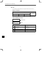
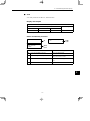
Parameter Settings
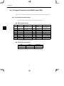
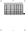
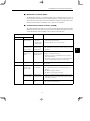
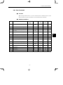
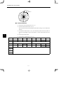
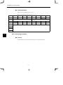
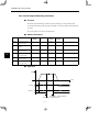
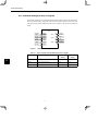
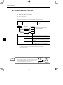
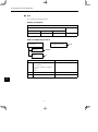
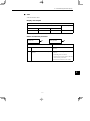
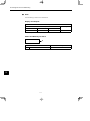
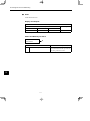
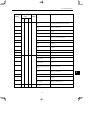
4.2.5 Positioning Parameters
4.2.5 Positioning Parameters
The positioning parameter table is shown below.
No.
4
Name
Range
Units
Effective Default Value
Timing
Type
Pn850
Positioning Deadband
0 to 10,000
Steps
Immediate 5
A
Pn851
Positioning Timeout
0 to 100,000
ms
Immediate 0
A
Pn852
Positioning Proximity
Detection Width
0 to 32,767
Steps
Immediate 10
B
Pn853
Direction for Rotation
System
0, 1
−
Immediate 0
B
Pn854
Approach Speed for
External Positioning
1 to 240,000
1,000
steps/min
Immediate 24,000
B
Pn855
Travel Distance for
External Positioning
0 to 99,999,999
Steps
Immediate 0
B
Pn856
Function Selection for
External Positioning
0 to 1
−
Power-up
1
B
Pn85A
Number of Stations
1 to 32,767
−
Immediate 1
B
Note: 1. “Steps” means “reference unit.” For reference unit details, refer to 4.3.1 Unit Parameters.
2. If you set the reference unit to 0.001 mm, 1,000 steps/min becomes mm/min.
4 -8
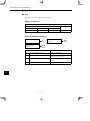
4.2 Parameter Tables
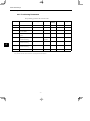
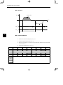
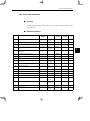
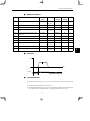
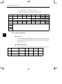
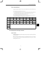
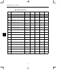
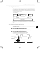
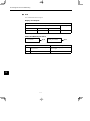
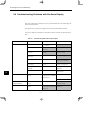
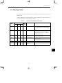
4.2.6 Multi-speed Positioning Parameters
A table of multi-speed positioning parameters is shown below.
No.
Name
Range
Units
Effective
Timing
Pn861
Number of Points for Speed Switching
0 to 16
−
Pn862
Initial Feed Speed for Multi-speed Positioning
1 to 240,000
1000
Immediate
steps/min
Pn863
Speed Switching Position 1
0 to 99,999,999 Steps
Pn864
Speed Switching Position 2
Pn865
Type
0
C
24,000
C
Immediate
0
C
0 to 99,999,999 Steps
Immediate
0
C
Speed Switching Position 3
0 to 99,999,999 Steps
Immediate
0
C
Pn866
Speed Switching Position 4
0 to 99,999,999 Steps
Immediate
0
C
Pn867
Speed Switching Position 5
0 to 99,999,999 Steps
Immediate
0
C
Pn868
Speed Switching Position 6
0 to 99,999,999 Steps
Immediate
0
C
Pn869
Speed Switching Position 7
0 to 99,999,999 Steps
Immediate
0
C
Pn86A
Speed Switching Position 8
0 to 99,999,999 Steps
Immediate
0
C
Pn86B
Speed Switching Position 9
0 to 99,999,999 Steps
Immediate
0
C
Pn86C
Speed Switching Position 10
0 to 99,999,999 Steps
Immediate
0
C
Pn86D
Speed Switching Position 11
0 to 99,999,999 Steps
Immediate
0
C
Pn86E
Speed Switching Position 12
0 to 99,999,999 Steps
Immediate
0
C
Pn86F
Speed Switching Position 13
0 to 99,999,999 Steps
Immediate
0
C
Pn870
Speed Switching Position 14
0 to 99,999,999 Steps
Immediate
0
C
Pn871
Speed Switching Position 15
0 to 99,999,999 Steps
Immediate
0
C
Pn872
Speed Switching Position 16
0 to 99,999,999 Steps
Immediate
0
C
Pn873
Switching Speed 1
1 to 240,000
1000
Immediate
steps/min
24,000
C
Pn874
Switching Speed 2
1 to 240,000
1000
Immediate
steps/min
24,000
C
Pn875
Switching Speed 3
1 to 240,000
1000
Immediate
steps/min
24,000
C
Pn876
Switching Speed 4
1 to 240,000
1000
Immediate
steps/min
24,000
C
Pn877
Switching Speed 5
1 to 240,000
1000
Immediate
steps/min
24,000
C
Pn878
Switching Speed 6
1 to 240,000
1000
Immediate
steps/min
24,000
C
4 -9
Immediate
Default
Value
4
Parameter Settings
4.2.7 Notch Output Parameters
No.
4
Name
Range
Units
Effective
Timing
Default
Value
Type
Pn879
Switching Speed 7
1 to 240,000
1000
Immediate
steps/min
24,000
C
Pn87A
Switching Speed 8
1 to 240,000
1000
Immediate
steps/min
24,000
C
Pn87B
Switching Speed 9
1 to 240,000
1000
Immediate
steps/min
24,000
C
Pn87C
Switching Speed 10
1 to 240,000
1000
Immediate
steps/min
24,000
C
Pn87D
Switching Speed 11
1 to 240,000
1000
Immediate
steps/min
24,000
C
Pn87E
Switching Speed 12
1 to 240,000
1000
Immediate
steps/min
24,000
C
Pn87F
Switching Speed 13
1 to 240,000
1000
Immediate
steps/min
24,000
C
Pn880
Switching Speed 14
1 to 240,000
1000
Immediate
steps/min
24,000
C
Pn881
Switching Speed 15
1 to 240,000
1000
Immediate
steps/min
24,000
C
Pn882
Switching Speed 16
1 to 240,000
1000
Immediate
steps/min
24,000
C
Note: 1. “Steps” means “reference unit.” For reference unit details, refer to 4.3.1 Unit Parameters.
2. If you set the reference unit to 0.001 mm, 1,000 steps/min becomes mm/min.
4.2.7 Notch Output Parameters
The notch output parameter table is shown below.
No.
Name
Range
Units
Effective
Timing
Default
Value
Type
Pn890
Notch Signal Output
Position Setting
0, 1
−
Immediate
0
C
Pn891
Notch Signal Output
Setting
0 to 3
−
Immediate
0
C
Pn892
Notch 1 Output
Position Lower Limit
±99,999,999
Steps
Immediate
0
C
Pn893
Notch 1 Output
Position Upper Limit
±99,999,999
Steps
Immediate
0
C
Pn894
Notch 2 Output
Position Lower Limit
±99,999,999
Steps
Immediate
0
C
Pn895
Notch 2 Output
Position Upper Limit
±99,999,999
Steps
Immediate
0
C
Note: 1. “Steps” means “reference unit.” For reference unit details, refer to 4.3.1 Unit Parameters.
2. If you set the reference unit to 0.001 mm, 1,000 steps/min becomes mm/min.
4 -10
4.3 Parameter Details
4.3 Parameter Details
4.3.1 Unit Parameters
The unit for performing positioning using a NS500 Unit is determined by the following two
parameters.
No.
Name
Range
Units
Effective
Timing
Default
Value
Type
Pn810
Electronic gear (numerator)
1 to 10,000,000
−
Power-up
1
B
Pn811
Electronic gear
(denominator)
1 to 10,000,000
−
Power-up
1
B
The electronic gear function can be used to set the position command units equal to the amount
of encoder pulses. The host controller can generate position commands in more familiar userdefined units such as millimeters or inches.
J Not Using the Electronic Gear
If not using the electronic gear, set Pn810 and Pn811 to 1. This will set the reference unit to
1 pulse, so you must calculate the scale position units using the host controller.
SGDH
NS500
1 pulse
PG
Motor
m
No. of Encoder pulses =
2048 × 4
1 pulse
7 revolutions
5 revolutions
n
Pitch of ball screw
P = 6 mm
IMPORTANT
In this manual, the reference unit explained in Electronic Gear Settings When Using a Ball Screw in 4.3.1 Unit
Parameters is based on a unit of 0.001 mm. The speed and other parameters must be interpreted as follows:
S Pn821: Feed Speed for Positioning (mm/min) → (1000 pulses/min)
4 -11
4
Parameter Settings
4.3.1 Unit Parameters
J Electronic Gear Settings When Using a Ball Screw
If using a ball screw, first check the following specifications.
D Number of Encoder pulses
D Gear ratio
D Ball screw pitch
System Example
The following system example shows the formulas when the reference unit is set to 0.001 mm.
SGDH
NS500
0.001 mm
PG
Motor
m
0.001 mm
7 revolutions
4
No. of Encoder pulses=
2,048 × 4
5 revolutions
n
Pitch of ball screw
P = 6 mm
D REV =
Travel distance of load per revolution (mm)
= 6 mm = 6000
0.001 mm
Reference unit (mm)
D A = (REV) × {Gear ratio (load rev.)} = 6000 × 5 = 30000
D B = (Encoder pulses) × (Pulse multiplier) × {Gear ratio (motor rev.)} = 2048 × 4 × 7 = 57344
D B/A = 57344/30000 = 1.911
Data ranges are shown below.
D A ≦ 10,000,000
D B ≦ 10,000,000
D 100 ≧
B/A ≧ 0.01
By storing the value of A in Pn811 and the value of B in Pn810, you can use the Electronic Gear
function. These parameters are enabled when the power is turned ON. After you have changed
the parameter, execute the Module Reset Command or the Reset Service to the Identity Object.
IMPORTANT
Setting B/A outside the range 0.01 to 100 may result in a misoperation. Make sure to set B and A within this
range.
4 -12
4.3 Parameter Details
J Electronic Gear Settings when Using a Rotary Table
If using a rotary table, first check the following specifications.
D Number of Encoder pulses
D Gear ratio
System Example
The following system example shows the formulas when the reference unit is set to 0.001°.
SGDH
NS500
0.001°
PG
Motor
m
No. of Encoder pulses =
2048 × 4
0.001°
3 revolutions
4
1 revolution
n
Rotating load
360°/revolution
D REV = 360°/0.001° = 36000
D A = REV × {Gear Ratio (load rev.)} = 36000 × 1 = 36000
D B = (Encoder pulses ) × (Pulse multiplier) × {Gear ratio (motor rev.)} = 2048 × 4 × 3 = 24576
Data ranges are shown below.
D A ≦ 10,000,000
D B ≦ 10,000,000
D 100 ≧
B/A ≧ 0.01
By storing the value of A in Pn811 and the value of B in Pn810, you can use the Electronic Gear
function. These parameters are enabled when the power is turned ON. After you have changed
the parameter, execute the Module Reset Command or the Reset Service to the Identity Object.
IMPORTANT
Setting B/A outside the range 0.01 to 100 may result in a misoperation. Make sure to set B and A within this
range.
4 -13
Parameter Settings
4.3.2 Zero Point Return Parameters
4.3.2 Zero Point Return Parameters
J Zero Point Return Types
The following four types of zero point return are supported.
Type 0
This zero point return type returns to the zero point using the deceleration limit switch signal
(DEC signal) and the phase C pulse of the encoder. The outline of the operation is as follows:
1. The axis travels in the direction specified as the zero point direction in the Zero Point
Return Function Selection (Pn801) at the Zero Point Return Feed Speed (Pn802).
2. When the deceleration limit switch status changes, the axis decelerates and travels at the
Zero Point Return Approach Speed (Pn803).
4
3. When the deceleration limit switch status changes again, the axis decelerates further when
the first encoder phase C pulse is detected and then travels at the Zero Point Return Creep
Speed (Pn804).
4. The axis travels the Zero Point Return Final Travel Distance (Pn805) from the position
where the phase C was detected, and that position becomes the zero point.
Zero point return feed speed
(Pn802)
Zero point return approach speed
(Pn803)
Zero point return creep
speed (Pn804)
Speed
Zero point return final
travel distance (Pn805)
Time
Dog width
Deceleration limit
switch signal
Machine coordinate
system zero point
Phase C
Zero point area
Type 1
This zero point return type returns to the zero point using the zero point signal (ZERO signal).
The outline of the operation is as follows:
1. The axis travels in the direction specified as the zero point direction in the Zero Point
Return Function Selection (Pn801) at the Zero Point Return Approach Speed (Pn803).
2. When the zero point signal status changes, the axis decelerates, and travels at the Zero
Point Return Creep Speed (Pn804).
4 -14
4.3 Parameter Details
3. The axis travels the Zero Point Return Final Travel Distance (Pn805) from the position that
the zero point signal status changed, and that position becomes the zero point.
Zero point return approach speed
(Pn803)
Zero point return creep speed
(Pn804)
Speed
Zero point return final travel
distance (Pn805)
Time
Zero point signal
Machine coordinate
system zero point
Zero point area
Type 2
This zero point return type returns to the zero point using the deceleration limit switch (DEC
signal) and the zero point signal (ZERO signal). The outline of the operation is as follows:
1. The axis travels in the direction specified as zero point direction in the Zero Point Return
Function Selection (Pn801) at the Zero Point Return Feed Speed (Pn802).
2. When the deceleration limit switch status changes, the axis decelerates, and travels at the
Zero Point Return Approach Speed (Pn803).
3. When the zero point signal changes, the axis decelerates further and travels at the Zero
Point Return Creep Speed (Pn804).
4. The axis travels the Zero Point Return Final Travel Distance (Pn805) from the position
where the zero point signal changed, and that position becomes the zero point.
Zero point return feed speed
(Pn802)
Zero point return approach speed
(Pn803)
Speed
Zero point return creep
speed (Pn804)
Zero point return final
travel distance (Pn805)
Time
Dog width
Deceleration limit switch
signal
Zero point signal
Machine coordinate system
zero point
Zero point area
4 -15
4
Parameter Settings
4.3.2 Zero Point Return Parameters
Type 3
This zero point return type returns to the zero point using the phase C pulse of the encoder only.
The outline of the operation is as follows:
1. The axis travels in the direction specified as zero point direction in the Zero Point Return
Function Selection (Pn801) at the Zero Point Return Approach Speed (Pn803).
2. When the first phase C pulse of the encoder is detected, the axis decelerates, and travels
at the Zero Point Return Creep Speed (Pn804).
3. The axis travels the Zero Point Return Final Travel Distance (Pn805) from the position
where the phase C pulse was detected, and that position becomes the zero point.
Zero point return approach speed
(Pn803)
Zero point return creep
speed (Pn804)
Speed
Zero point return final
travel distance (Pn805)
4
Time
Phase C pulse
Machine coordinate
system zero point
Zero point
area
INFO
When the setting for the Zero Point Return Final Travel Distance (Pn805) is small (when the distance
is shorter than the distance required for the deceleration from approach speed), the axis will travel
past the zero point and then return to it from the other direction.
Zero point return approach speed
Zero point return final travel distance
Amount of overtravel
Returning the amount
overtraveled
Time
Phase C pulse
Zero point
4 -16
4.3 Parameter Details
J Parameter Details (Object 0x64)
The details of parameters relating to zero point return are shown below.
Zero Point Return Mode (Pn800)
The zero point return type is specified in the zero point return mode.
Zero Point
Return Mode
Zero Point Return Type
0
3-step deceleration using deceleration limit switch and phase
C pulse
1
Double-step deceleration using zero point signal
2
3-step deceleration using deceleration limit switch and zero
point signal
3
Double-step deceleration using phase C pulse
Zero Point Return Function Selection (Pn801)
The zero point return function selection has the following bit settings.
Bit
Name
Description
0
Zero Point Return Direction Setting*
0: Positive direction
1: Negative direction
1
Deceleration Limit Switch Signal
Setting
0: Enabled on Low
1: Enabled on High
2
Zero Point Signal Setting
0: Enabled on leading edge
1: Enabled on trailing edge
Reserved
−
3 to 15
Zero Point Return Feed Speed (Pn802)
Use the Zero Point Return Feed Speed to set the initial feed speed for 3-step deceleration zero
point return.
The setting unit is 1,000 steps/min.
Zero Point Return Approach Speed (Pn803)
Use the Zero Point Return Approach Speed to set the approach speed for zero point return. The
setting unit is 1,000 steps/min.
Zero Point Return Creep Speed (Pn804)
Use the Zero Point Return Creep Speed to set the creep speed for zero point return. The setting
unit is 1,000 steps/min.
4 -17
4
Parameter Settings
4.3.2 Zero Point Return Parameters
Zero Point Return Final Travel Distance (Pn805)
Use the Zero Point Return Final Travel Distance to set the distance from the position where
the encoder phase C and zero point signal were detected to the machine zero point. The setting
unit is steps.
Zero Point Output Width (Pn806)
Use the Zero Point Output Width to set the area that will be regarded as the zero point. The
setting unit is steps.
In the following diagram, if the conditions outlined below are met, the Zero Point Flag in the
response data will be set to 1.
D X = | Zero point − Current position | ≦ Pn806
Zero point
Current position
Position
4
Pn806
Pn806
X
Zero Point Offset (Pn809)
The system automatically writes to the Zero Point Offset the value of the offset from the zero
point on the encoder when the zero point setting in the absolute value detection system has been
completed. Normally, this parameter does not need to be set.
When using an absolute value detection system, set this value to enable adjustment of the zero
point.
Zero Point Return Acceleration/Deceleration Time (Pn80A)
Use the Zero Point Return Acceleration/Deceleration Time to set the acceleration/declaration
time constant used during zero point return. The setting unit is ms. Single-step linear acceleration/deceleration is used for zero point return. Refer to 4.3.4 Speed, Acceleration, and Deceleration for information on this acceleration/deceleration type.
4 -18
4.3 Parameter Details
4.3.3 Machine System and Peripheral Devices
The details of parameters relating to the machine system and peripheral devices are shown below.
Coordinate Type (Pn812)
Use the Coordinate Type to set whether to use the NS500 Unit as a linear axis or rotary axis.
Pn812
0
Description
The linear axis is designated.
The unit of current value data: steps
1
The rotary axis is designated.
The unit of current value data: degrees
Reference Units per Machine Rotation (Pn813)
Use the Reference Units per Machine Rotation to set the reference unit for one machine rotation. This parameter is enabled only when the coordinate type is set to rotary axis. If this parameter is not set correctly, when the machine performs a 360° rotation, the current position will
not be reset to 0°, so be careful.
The setting unit is steps. The initial value is 360,000.
Backlash Compensation (Pn814)
Use the Backlash Compensation to set the amount of compensation when backlash compensation is used. The setting unit is steps.
Backlash Compensation Direction (Pn815)
Use the Backlash Compensation Direction to set the direction of the backlash compensation.
Normally, set this parameter in the opposite direction to the zero point direction.
Pn815
Description
0
Positive Direction
1
Negative Direction
Positive Software Limit (Pn816)
Use the Positive Software Limit to set the software limit in the positive direction. The setting
unit is reference unit. Make the setting between −99,999,999 and 99,999,999.
Negative Software Limit (Pn817)
Use the Negative Software Limit to set the software limit in the negative direction. The setting
unit is reference unit. Make the setting between −99,999,999 and 99,999,999.
4 -19
4
Parameter Settings
4.3.3 Machine System and Peripheral Devices
Machine Function Selection (Pn818)
Use the Machine Function Selection to set whether or not to use the software limit functions
and the backlash compensation functions.
Bit
Description
0
0: Software Limit is disabled.
1: Software Limit is enabled.
1
0: Backlash Compensation is disabled.
1: Backlash Compensation is enabled.
Hardware Limit Signal Function Selection (Pn819)
Use the Hardware Limit Signal Function Selection to set whether or not to use the hardware
limit and to set the signal polarity.
Bit
4
Name
0
Description
Enable/Disable Hardware LImit
0: Enabled
1: Disabled
1
Hardware Limit Signal Polarity
0: Enabled on Low
1: Enabled on High
2 to 15
Reserved
−
Hardware Limit Action (Pn81A)
Use the Hardware Limit Action to set the operation of the NS500 Unit when a hardware limit
is detected.
Pn81A
Description
0
Servo OFF
1
Hard Stop: Stops at the specified maximum torque.
2
Deceleration to a Stop: Stops according to the specified deceleration curve.
3 to 255
Reserved
4 -20
4.3 Parameter Details
Emergency Stop Signal Function Selection (Pn81B)
Use the Emergency Stop Signal Function Selection to set whether or not to use the emergency
stop function and to set the polarity of the signal.
Bit
0
1
2 to 15
Name
Description
Enable/disable
Emergency Stop
0: Disabled
Emergency Stop
Signal Polarity
0: Disabled on Low
Reserved
−
1: Enabled
1: Enabled on High
4.3.4 Speed, Acceleration, and Deceleration
J Acceleration and Deceleration Patterns
The following acceleration and deceleration patterns are possible by combining acceleration/
deceleration types (Pn826 or Pn836) and filters (Pn829).
Acceleration/Deceleration Type (Pn826 or Pn836)
0: None
Filter
Selection
((Pn829))
0: None
No acceleration and
deceleration
1: Single-step
Linear
Single-step Linear
Accel/Decel
2: Double-step
Linear
Double-step Linear
Accel/Decel
3: Asymmetric
Asymmetric Linear
Accel/Decel
ConstantAccel/Decel*1 ConstantAccel/Decel*1 ConstantAccel/Decel*1
1: Exponent
−
−
−
−
−
−
Single-step Linear
Accel/Decel
S-curve Accel/Decel
Time
−
Asymmetric S-curve
Accel/Decel
Constant Accel/Decel
time*2
ConstantAccel/Decel*1
Exponential
Accel/Decel
Constant Accel/Decel
time*2
2: Exponent
with Bias
Exponential Accel/Decel with Bias
Constant Accel/Decel
time*2
3: Travelling
Average
ConstantAccel/Decel*1
* 1. With Constant Accel/Decel, the time required for acceleration and deceleration changes with the feed speed changes.
* 2. With Constant Accel/Decel time, the time required for acceleration and deceleration does not change even if the feed speed
changes.
Note: Combinations other than those given above may result in incorrect acceleration and deceleration.
4 -21
4
Parameter Settings
4.3.4 Speed, Acceleration, and Deceleration
Single-step Linear Acceleration/Deceleration with Constant
Acceleration/Deceleration
Table 4.4
Related Parameters
Pnjjj
Name
Pn826
Acceleration/Deceleration Type for Positioning
(= 1)
Pn829
Filter Selection (= 0)
Pn821
Feed Speed for Positioning
Pn822
Acceleration Time for Positioning
Pn843
Maximum Feed Speed
Pn821
4
Pn822
Figure 4.1
Pn822
Pn843
Speed
Time
Single-step Linear Acceleration/Deceleration with Constant
Acceleration/Deceleration
4 -22
4.3 Parameter Details
Double-step Linear Acceleration/Deceleration with Constant
Acceleration/Deceleration
Related Parameters
Pnjjj
Name
Pn826
Acceleration/Deceleration Type for Positioning
(= 2)
Pn829
Filter Selection (= 0)
Pn821
Feed Speed for Positioning
Pn822
Acceleration Time Constant for Positioning
Pn824
Switch Speed for Second Accel/Decel
Pn825
Accel/Decel Time Constant of Second Accel/Decel
Pn843
Maximum Feed Speed
Pn825
4
Pn825
Pn824
Pn841
Speed
Pn822
Figure 4.2
Pn822
Pn843
Table 4.5
Time
Double-step Linear Acceleration/Deceleration with Constant
Acceleration/Deceleration
4 -23
Parameter Settings
4.3.4 Speed, Acceleration, and Deceleration
Asymmetric Linear Acceleration/Deceleration with Constant
Acceleration/Deceleration
Table 4.6
Related Parameters
Pnjjj
Name
Pn826
Acceleration/Deceleration Type for Positioning
(= 3)
Pn829
Filter Selection (= 0)
Pn821
Feed Speed for Positioning
Pn822
Acceleration Time for Positioning
Pn823
Deceleration Time for Positioning
Pn843
Maximum Feed Speed
Speed
Pn822
Figure 4.3
Pn823
Pn843
Pn821
4
Time
Asymmetric Linear Acceleration/Deceleration with Constant
Acceleration/Deceleration
4 -24
4.3 Parameter Details
Exponential Acceleration/Deceleration with Constant
Acceleration/Deceleration Time
Table 4.7
Related Parameters
Pnjjj
Name
Pn826
Acceleration/Deceleration Type for Positioning
(= 0)
Pn829
Filter Selection (= 1)
Pn821
Feed Speed for Positioning
Pn840
Time Constant for Exponential Acceleration/Deceleration
Pn821
Speed
Pn840
Figure 4.4
Pn840
4
Time
Exponential Acceleration/Deceleration with Constant
Acceleration/Deceleration Time
4 -25
Parameter Settings
4.3.4 Speed, Acceleration, and Deceleration
Exponential Acceleration/Deceleration with Bias with Constant
Acceleration/Deceleration Time
Table 4.8
Related Parameters
Pnjjj
Name
Pn826
Acceleration/Deceleration Type for Positioning
(= 0)
Pn829
Filter Selection (= 2)
Pn821
Feed Speed for Positioning
Pn840
Time Constant for Exponential Acceleration/Deceleration
Pn841
Bias Speed for Exponential Acceleration/Deceleration
Speed
Pn841
Pn821
4
Pn840
Figure 4.5
Pn840
Time
Exponential Acceleration/Deceleration with Bias with Constant
Acceleration/Deceleration Time
4 -26
4.3 Parameter Details
Single-step Linear Acceleration/Deceleration with Constant
Acceleration/Deceleration Time
Table 4.9
Related Parameters
Pnjjj
Name
Pn826
Acceleration/Deceleration Type for Positioning
(= 0)
Pn829
Filter Selection (= 3)
Pn821
Feed Speed for Positioning
Pn842
Time Constant of Travelling Average
Pn821
Speed
Pn841
4
Pn842
Figure 4.6
Pn842
Time
Single-step Linear Acceleration/Deceleration with Constant
Acceleration/Deceleration Time
4 -27
Parameter Settings
4.3.4 Speed, Acceleration, and Deceleration
S-curve Acceleration/Deceleration with Constant
Acceleration/Deceleration
Table 4.10 Related Parameters
Pnjjj
Name
Pn826
Acceleration/Deceleration Type for Positioning
(= 1)
Pn829
Filter Selection (= 3)
Pn821
Feed Speed for Positioning
Pn822
Acceleration Time for Positioning
Pn842
Time Constant of Travelling Average
Pn843
Maximum Feed Speed
Speed
Pn843
Pn821
4
Time
Pn822
Pn822
Pn842
Figure 4.7
Pn842
S-curve Acceleration/Deceleration with Constant
Acceleration/Deceleration
4 -28
4.3 Parameter Details
Asymmetric S-curve Acceleration/Deceleration with Constant
Acceleration/Deceleration
Table 4.11 Related Parameters
Pnjjj
Name
Pn826
Acceleration/Deceleration Type for Positioning
Pn829
Filter Selection
Pn821
Feed Speed for Positioning (mm/min)
Pn822
Acceleration Time for Positioning
Pn823
Deceleration Time for Positioning
Pn842
Time Constant for Travelling Average
Pn843
Maximum Feed Speed
Speed
Pn843
Pn821
4
Time
Pn822
Pn823
Pn842
Figure 4.8
Pn842
Asymmetric S-curve Acceleration/Deceleration with Constant
Acceleration/Deceleration
4 -29
Parameter Settings
4.3.4 Speed, Acceleration, and Deceleration
J Parameter Details
Feed Speed for Positioning (Pn821)
Use the Feed Speed for Positioning to set the feed speed of the positioning. The setting unit
is 1,000 steps/min.
Acceleration Time for Positioning (Pn822)
Use the Acceleration Time for Positioning to set the acceleration time for the positioning. The
setting unit is ms.
Deceleration Time for Positioning (Pn823)
Use the Deceleration Time for Positioning to set the deceleration time for positioning. The setting unit is ms.
This parameter is enabled only when the Acceleration/Deceleration Type for Positioning
(Pn826) is set to the asymmetrical linear acceleration and deceleration.
4
Switch Speed for Second Acceleration/Deceleration for
Positioning (Pn824)
Use the Switch Speed for Second Acceleration/Deceleration for Positioning to set the switching speed to acceleration and deceleration of the second step when using double-step linear
acceleration and deceleration. The setting unit is 1,000 step/min.
This parameter is enabled only when the Acceleration/Deceleration Type for Positioning
(Pn826) is set to double-step linear acceleration and deceleration.
Acceleration/Deceleration Time for Second
Acceleration/Deceleration for Positioning (Pn825)
Use the Acceleration/Deceleration Time for Second Acceleration/Deceleration for Positioning to set the acceleration and deceleration time for the second step when using double-step
linear acceleration and deceleration. The setting unit is ms.
This parameter is enabled only when the Acceleration/Deceleration Type for Positioning
(Pn826) is set to double-step linear acceleration and deceleration.
Acceleration/Deceleration Type for Positioning (Pn826)
Use the Acceleration/Deceleration Type for Positioning to set the type of acceleration and deceleration for the positioning.
You can set eight different acceleration and deceleration patterns using different combinations
of Acceleration/Deceleration Type for Positioning and Filter Selection (Pn829).
Setting
Description
0
None
1
Single Step Linear
4 -30
4.3 Parameter Details
Setting
Description
2
Double Step Linear
3
Asymmetric
External Positioning Feed Speed (Pn827)
Use the External Positioning Feed Speed to set the feed speed for external positioning.
The setting unit is 1,000 steps/min.
Filter Selection (Pn829)
Use the Filter Selection to set the acceleration and deceleration filter type. This parameter is
used in common by the positioning, constant feeding, and zero point return operations.
Setting
Description
0
None
1
Exponential
2
Exponential with Bias
3
Travelling Average
4
Constant Feed Reference Unit Selection (Pn830)
Use the Constant Feed Reference Unit Selection to set the reference unit for the speed setting
for a constant feed command data.
Setting
Description
0
Sets an override value (%) for the feed speed for FEED (Pn831) in the command data.
1
Speed set directly in the command data.
The setting unit is 1000 steps/min.
Constant Feed Speed (Pn831)
Use the Constant Feed Speed to set the feed speed when using the FEED operation. The setting
unit is 1,000 steps/min.
Acceleration Time for Constant Feed (Pn832)
Use the Acceleration Time for Constant Feed to set the acceleration time when using the feed
operation. The setting unit is ms.
Deceleration Time for Constant Feed (Pn833)
Use the Deceleration Time for Constant Feed to set the deceleration time when using asymmetrical acceleration and deceleration with the constant feed operation. The setting unit is ms.
4 -31
Parameter Settings
4.3.4 Speed, Acceleration, and Deceleration
This parameter is enabled only when the Acceleration/Deceleration Type for Constant Feed
(Pn836) is set to asymmetrical linear acceleration and deceleration.
Switch Speed for Constant Feed Second Accel/Decel (Pn834)
Use the Switch Speed for Constant Feed Second Acceleration/Deceleration to set the switching
speed to double-step acceleration and deceleration when using double-step linear acceleration
and deceleration with the constant feed operation. The setting unit is 1,000 steps/min.
This parameter is enabled only when the Acceleration/Deceleration Type for Constant Feed
(Pn836) is set to double-step linear acceleration and deceleration.
Accel/Decel Time for Constant Feed Second Accel/Decel (Pn835)
Use the Acceleration/Deceleration Time for Constant Feed Second Acceleration/Deceleration
to set the second acceleration/deceleration time when using double-step linear acceleration
and deceleration with the constant feed operation. The setting unit is ms.
This parameter is enabled only when the Acceleration/Deceleration Type for Constant Feed
(Pn836) is set to double-step linear acceleration and deceleration.
4
Acceleration/Deceleration Type for Constant Feed (Pn836)
Use the Acceleration/Deceleration Type for Constant Feed to set the acceleration and deceleration type with the constant feed operation.
You can set eight different acceleration and deceleration patterns using different combinations
of Acceleration/Deceleration Type for Constant Feed and Filter Selection (Pn829).
Setting
Description
0
None
1
Single Step Linear
2
Double Step Linear
3
Asymmetric
Time Constant for Exponential Acceleration/Deceleration (Pn840)
Use the Time Constant for Exponential Acceleration/Deceleration to set the time constant
when using exponential acceleration and deceleration. This parameter is used in common by
the positioning and the continuous rotary operation. The setting unit is ms.
Bias Speed for Exponential Acceleration/Deceleration (Pn841)
Use the Bias Speed for Exponential Acceleration/Deceleration to set the bias speed of the exponential acceleration and deceleration. The setting unit is 1,000 steps/min.
Time Constant of Travelling Average (Pn842)
Use the Time Constant of Travelling Average to set the time constant of the average travel
speed of the acceleration and deceleration. This parameter is used in common by the positioning and the continuous rotary operation. The setting unit is ms.
4 -32
4.3 Parameter Details
Maximum Feed Speed (Pn843)
Use the Maximum Feed Speed to set the maximum feed speed of the positioning, FEED, and
zero point return operations. The acceleration and deceleration data is calculated from this data
and the time constants. The setting unit is 1,000 steps/min.
Step Distance 1 (Pn844)
Use the Step Distance 1 to set the amount of travel when executing step operation. This value
is used when the 0 has been specified as the command data in a command data.
The setting unit is steps.
Step Distance 2 (Pn845)
Use the Step Distance 2 to set the amount of travel when executing step operation. This value
is used when the 1 has been specified as the command data in a command data.
The setting unit is steps.
Step Distance 3 (Pn846)
Use the Step Distance 3 to set the amount of travel when executing step operation. This value
is used when the 2 has been specified as the command data in a command data.
The setting unit is steps.
Step Distance 4 (Pn847)
Use the Step Distance 4 to set the amount of travel when executing step operation. This value
is used when the 3 has been specified as the command data in a command data.
The setting unit is steps.
4.3.5 Positioning Parameters
J Parameter Details
Positioning Deadband (Pn850)
Use the Positioning Deadband to set the positioning completed range, i.e., to determine if the
axis is on-target position. The setting unit is steps. When the positioning deadband is set to 0,
no on-target position check will be performed.
Current value
that is changing
End Point
Coordinate axis
Pn850 Pn850
X
Positioning Deadband
4 -33
4
Parameter Settings
4.3.5 Positioning Parameters
When the following condition is satisfied in the above figure, the axis is viewed as being at
the on-target position and the On-target Flag in the response data will be set to 1.
D X = (End point − Current value) ≤ Pn850
Positioning Timeout (Pn851)
Use the Positioning Timeout to set the time for performing on-target position check. The setting unit is ms. If, after the move command distribution has been completed, the positioning
completed range is not entered within the time set, A.9A positioning a completion timeout
warning will be sent.
If this parameter is set to 0, the check time becomes infinite.
Positioning Proximity Detection Width (Pn852)
Use the Positioning Proximity Detection Width to set the range for positioning area proximity
to be detected. If the difference between the current position and the target position are within
this parameter range, the proximity signal in the response data will be set to 1. The setting unit
is steps.
4
Direction for Rotation System (Pn853)
Use the Direction for Rotation System to set the rotation direction for when Station Commands
or rotation commands using absolute values are used.
Setting
Description
0
Uses the rotation direction in command data.
1
Uses the direction for the shortest travel.
Approach Speed for External Positioning (Pn854)
Use the Approach Speed for External Positioning to set the approach speed after the external
signal has reversed status for an external positioning command.
The setting unit is 1,000 steps/min.
Travel Distance for External Positioning (Pn855)
Use the Travel Distance for External Positioning to set the travel distance after the external
signal has reversed status for an external positioning command.
The setting unit is steps.
Function Selection for External Positioning (Pn856)
Use the Function Selection for External Positioning to select the polarity of the external signal.
Bit
0
2 to 15
Name
Description
External Signal Po- 0: Enabled on low
larity
1: Enabled on high
Reserved
−
4 -34
4.3 Parameter Details
Number of Stations (Pn85A)
Use the Number of Stations to set how many stations one revolution of the servomotor will be
evenly split into when Station Commands are used.
In Station Commands, equally divided stations are numbered in order from 0 and positioning
is performed by specifying a station number.
Station n
Station 0
Station 1
4.3.6 Multi-speed Positioning
4
By using multi-speed positioning, the speed can be changed in stages during positioning.
Up to 16 speed change stages are possible.
When the axis reaches a specified position, the speed switches to the speed for the next stage
and the axis travels to the specified position in that next stage.
Time
Speed switching position 3
(Pn865)
Speed 2
(Pn874)
Speed 1
(Pn873)
Feed speed
(Pn862)
Speed switching position 2
(Pn864)
Speed switching position 1 (Pn863)
Speed 3
(Pn875)
Speed
J Parameter Details
Number of Points for Speed Switching (Pn861)
Use the Number of Points for Speed Switching to set the number of points at which the speed
will be switched. If, for example, the parameters for speed switching positions were set from
1 to 16 but this setting for the number of points was set to 3, the speed switching would be enabled for 3 points only.
4 -35
Parameter Settings
4.3.7 Notch Signal Output Positioning
Initial Feed Speed for Multi-speed Positioning (Pn862)
Use the Initial Feed Speed for Multi-speed Positioning to set the initial feed speed when performing speed multi-step positioning. This speed will be enabled until the position in the speed
switching position 1 parameter is reached.
The setting unit is 1,000 steps/min.
Speed Switching Positions 1 to 16 (Pn872)
Use the Speed Switching Position to set the position at which the speed is to change at a position
relative to the start position. The speed switching position xx and switching speed xx are used
together. For example, the axis will travel from speed switching position 1 to speed switching
position 2 at speed 1.
The setting unit is steps.
Switching Speeds 1 to 16 (Pn873 to Pn882)
4
Use the Switching Speed to set the feed speed between specified speed switching positions.
For example, the axis will travel at speed 2 between speed switching position 2 and speed
switching position 3.
The setting unit is 1,000 steps/min.
4.3.7 Notch Signal Output Positioning
During the positioning, notch signals (NOTCH 1 and NOTCH 2) are output when specified
points are passed.
Two notch signals, NOTCH 1 and NOTCH 2, can be output.
Notch output 1 position lower limit (Pn892)
Notch output 1 position upper limit (Pn893)
Speed
Time
1
NOTCH 1
0
signal
4 -36
4.3 Parameter Details
J Parameter Details
Notch Signal Output Position Setting (Pn890)
Use the Notch Signal Output Position Setting to set whether absolute or relative positions are
set for the notch signal output position parameters.
Setting
Description
0
Setting absolute position.
1
Specifies relative position.
Notch Signal Output Setting (Pn891)
Use the Notch Signal Output Setting to set the polarity of the notch signal output.
Table 4.12 Notch Signal Output Setting
Setting
Description
0
Sets NOTCH 1 signal.
1
Sets NOTCH 2 signal.
Table 4.13
Bit 0/ Bit 1
Bit Meanings
Description
0
Normally: OFF When passed: ON
1
Normally: ON When passed: OFF
Notch 1 Output Position Lower Limit (Pn892)
Notch 1 Output Position Upper Limit (Pn893)
Use the Notch 1 Output Position Upper/Lower Limits to set the output position range for notch
signal (NOTCH 1). When the current position is inside this range, the status of the NOTCH
1 signal output is reversed based on the notch signal output setting.
Notch 2 Output Position Lower Limit (Pn894)
Notch 2 Output Position Upper Limit (Pn895)
Use the Notch 2 Output Position Upper/Lower Limits to set the output position range for notch
signal (NOTCH 2). When the current position is inside this range, the status of the NOTCH
2 signal output is reversed based on the notch signal output setting.
4 -37
4
5
PROFIBUS-DP Communications
This chapter explains about using PROFIBUS-DP communications to
execute commands and editing parameters for an NS500 Unit.
5.1 Specifications and Configuration . . . . . . . .
5.1.1 Specifications . . . . . . . . . . . . . . . . . . . . . . . . . . . . . . .
5.1.2 Control Configuration . . . . . . . . . . . . . . . . . . . . . . . .
5.2 PROFIBUS-DP Communications
Setting Switches . . . . . . . . . . . . . . . . . . . . . .
5 -2
5 -2
5 -2
5 -3
5.2.1 Rotary Switch Settings for Setting Station Address
5 -3
5.2.2 LED Indicators . . . . . . . . . . . . . . . . . . . . . . . . . . . . . .
5 -4
5.3 Command/Response Format . . . . . . . . . . . .
5 -6
5.3.1 Command Format . . . . . . . . . . . . . . . . . . . . . . . . . . .
5 -6
5.3.2 General Command Bits and Status . . . . . . . . . . . .
5 -7
5.3.3 Move command datas . . . . . . . . . . . . . . . . . . . . . . . .
5 -11
5.3.4 Set/Read command datas . . . . . . . . . . . . . . . . . . . .
5 -20
5.4 Motion Command Methods . . . . . . . . . . . . .
5 -27
5.4.1 Constant Feed Command . . . . . . . . . . . . . . . . . . . .
5 -27
5.4.2 Step Command . . . . . . . . . . . . . . . . . . . . . . . . . . . . .
5 -29
5.4.3 Station Command . . . . . . . . . . . . . . . . . . . . . . . . . . .
5 -31
5.4.4 Point Table Command . . . . . . . . . . . . . . . . . . . . . . . .
5 -33
5.4.5 Zero Point Return Command . . . . . . . . . . . . . . . . . .
5 -34
5.4.6 Positioning Command . . . . . . . . . . . . . . . . . . . . . . . .
5 -36
5.4.7 External Positioning . . . . . . . . . . . . . . . . . . . . . . . . .
5 -38
5.4.8 Notch Output Positioning Command . . . . . . . . . . .
5 -40
5.4.9 Multi-speed Positioning Command . . . . . . . . . . . . .
5 -41
5.5 Commands from the Host Controller . . . . .
5 -45
5.5.1 Basic Sequence . . . . . . . . . . . . . . . . . . . . . . . . . . . . .
5 -45
5.5.2 Command Method . . . . . . . . . . . . . . . . . . . . . . . . . . .
5 -46
5 -1
5
PROFIBUS-DP Communications
5.1.2 Control Configuration
5.1 Specifications and Configuration
5.1.1 Specifications
The NS500 Unit is classified as a PROFIBUS-DP slave device, and can be controlled from different types of PROFIBUS-DP Master Module as a general-purpose I/O Module with 64 inputs
and 64 outputs. Communications with the Master Module are cyclic; command datas are received cyclically from the Master Module and response datas are returned.
5.1.2 Control Configuration
An outline of the control configuration is shown below. A maximum of 32 NS500 Units or other
slave devices can be connected to one PROFIBUS-DP Master. (The configuration can be expanded to include up to 126 stations using repeaters.)
PROFIBUS-DP Master Module
PLC or personal computer
5
32 stations max. (Using repeaters, up
to 126 stations can be connected.)
SERVOPACK
SERVOPACK
Inverter
5 -2
Machine I/O signals
5.2 PROFIBUS-DP Communications Setting Switches
5.2 PROFIBUS-DP Communications Setting Switches
This section explains the switch settings required for PROFIBUS-DP communications.
5.2.1 Rotary Switch Settings for Setting Station Address
Use the rotary switches (×1, ×10) to set the PROFIBUS-DP station address. After making the
settings, cycle the communications power to enable the settings.
The station address can be set between 0 and 125. If you make a setting outside this range, a
setting error will occur.
Select the station address of the NS500 Unit using the switch settings as shown in the following
table.
5
5 -3
PROFIBUS-DP Communications
5.2.2 LED Indicators
× 10
×1
0
0
1
2
3
4
5
6
7
8
9
A
B
C
D
E
F
0
1
2
3
4
5
6
7
8
9
A
B
C
D
E
F
0
1
2
3
4
5
6
7
8
9
1
5
2
Station Address
Decimal in ( )
0
1
2
3
4
5
6
7
8
9
A (10)
B (11)
C (12)
D (13)
E (14)
F (15)
10 (16)
11 (17)
12 (18)
13 (19)
14 (20)
15 (21)
16 (22)
17 (23)
18 (24)
19 (25)
1A (26)
1B (27)
1C (28)
1D (29)
1E (30)
1F (31)
20 (32)
21 (33)
22 (34)
23 (35)
24 (36)
25 (37)
26 (38)
27 (39)
28 (40)
29 (41)
× 10
×1
2
A
B
C
D
E
F
0
1
2
3
4
5
6
7
8
9
A
B
C
D
E
F
0
1
2
3
4
5
6
7
8
9
A
B
C
D
E
F
0
1
2
3
3
4
5
Station Address
Decimal in ( )
2A (42)
2B (43)
2C (44)
2D (45)
2E (46)
2F (47)
30 (48)
31 (49)
32 (50)
33 (51)
34 (52)
35 (53)
36 (54)
37 (55)
38 (56)
39 (57)
3A (58)
3B (59)
3C (60)
3D (61)
3E (62)
3F (63)
40 (64)
41 (65)
42 (66)
43 (67)
44 (68)
45 (69)
46 (70)
47 (71)
48 (72)
49 (73)
4A (74)
4B (75)
4C (76)
4D (77)
4E (78)
4F (79)
50 (80)
51 (81)
52 (82)
53 (83)
× 10
×1
5
4
5
6
7
8
9
A
B
C
D
E
F
0
1
2
3
4
5
6
7
8
9
A
B
C
D
E
F
0
1
2
3
4
5
6
7
8
9
A
B
C
D
E
6
7
Station Address
Decimal in ( )
54 (84)
55 (85)
56 (86)
57 (87)
58 (88)
59 (89)
5A (90)
5B (91)
5C (92)
5D (93)
5E (94)
5F (95)
60 (96)
61 (97)
62 (98)
63 (99)
64 (100)
65 (101)
66 (102)
67 (103)
68 (104)
69 (105)
6A (106)
6B (107)
6C (108)
6D (109)
6E (110)
6F (111)
70 (112)
71 (113)
72 (114)
73 (115)
74 (116)
75 (117)
76 (118)
77 (119)
78 (120)
79 (121)
7A (122)
7B (123)
7C (124)
7D (125)
7E (126)
Note: Setting a value of 7F or more will result in an error (A.E8). The setting 7E (126) is used by the manufacturer for setup purposes. Set station addresses in the range 0 to 125.
5.2.2 LED Indicators
NS500 Units are equipped with two LED indicators, the Module Error indicator (ERR) to indicate the Unit status, and the Communications Status indicator (COMM) to indicate the PROFIBUS-DP communications status.
5 -4
5.2 PROFIBUS-DP Communications Setting Switches
J Module Error Indicator (ERR)
The Module Error indicator is a red LED that lights when a communications error occurs. It
turns OFF while communications data is being exchanged (i.e., during normal operation). It
lights at other times. The current status of the NS500 Unit is indicated, together with the Communications Status indicator (COMM), in the way shown in the table below.
J Communications Status Indicator (COMM)
The Communications Status indicator is a red and green dual-display LED and indicates PROFIBUS-DP communications errors. The current status of the NS500 Unit is indicated, together
with the Module Error indicator (ERR), in the way shown in the table below.
Indicator
ERR
ON
Status
Cause
COMM
Lights red and
green alternately.
S Performing self
diagnosis
S The NS500 Unit performs self diagnosis for approx. 2 seconds after power is turned ON.
S Invalid station
address setting
S A station address is set to 7F (127) or more.
Flashes green slow- Waiting for a paly (flashing cycle:
rameter message
approx. 0.5 Hz).
from the Master
Flashes green
(flashing cycle:
3 Hz).
S At startup, the Master has not yet sent a parameter message.
S The NS500 Unit is waiting for a parameter message sent from
the Master.
Waiting for a configuration message
from the Master
The NS500 Unit has received a valid parameter message and is
waiting for a configuration message.
S Normal start sequence: The NS500 Unit is in an extremely
short intermediate state.
S Error status: A parameter message was received from the Master, but a configuration message has not been received.
OFF
Lights green.
Exchanging data
Data is being exchanged between the Master and the Slave (normal operation).
ON
Flashes red slowly
(flashing cycle:
approx. 0.5 Hz).
Communications
not established
The NS500 Unit has not detected the baud rate.
S The communications cable is not connected properly, or is
defective.
S The Master changed the baud rate.
S The Master’s power supply has dropped.
Flashes red (flashing cycle: 3 Hz).
PROFIBUS-DP
watchdog timeout
S A message could not be received within the previously set bus
communications time. (The status is held until a new parameter message is received.)
Lights red.
NS500 Unit system
error
S Error detected by self diagnosis.
5 -5
S The system is not operating at all.
5
PROFIBUS-DP Communications
5.3.1 Command Format
5.3 Command/Response Format
This section explains command sent to an NS500 Unit from the Master and the response sent from
the NS500 Unit.
5.3.1 Command Format
This section explains the basic format of command sent to an NS500 Unit from the master device and the response sent from the NS500 Unit to the master device. Command and response
are in an 8-byte data format.
Command
[0]
0/1
Response
[0]
General command bits
[1]
[1]
[2]
[2]
[3]
[4]
0/1
General status
[3]
[4]
Command-dependant data
[5]
[5]
[6]
[6]
[7]
[7]
Command-dependant data
Both command and response are separated into two sections. Byte 0 is a general area and bytes
5
1 to 7 make up the command-dependant data area. The command-dependant data area can contain one of two types of commands, move commands and set/read commands. The type of command is defined by the most-significant bit (MSB) of byte 0.
J Format for Move Commands
Command
[0]
[1]
0
Response
Response type
[2]
Command code
[1]
General status
Response type
[2]
Command bit
[3]
0
[0]
General command bits
Status
[3]
[4]
Command code
[4]
[5]
[5]
Command data
[6]
Response data
[6]
[7]
[7]
J Format for Set/Read Commands
Command
[0]
[1]
[2]
[3]
1
Response
[0]
General command bits
0
Command code
[2]
Command number
[3]
[4]
[5]
[6]
[1]
1
General status
0
Command code
Command number
[4]
[5]
Command data
[6]
[7]
[7]
5 -6
Response data
5.3 Command/Response Format
5.3.2 General Command Bits and Status
J General Command Bits
The general command bit area is detailed below.
Table 5.1
General Command Bits
Byte
Bit 7
Bit 6
Bit 5
Bit 4
Bit 3
Bit 2
Bit 1
Bit 0
0
MOD
0
ALRST
ESTP
0
0
SVON
C_STRT
Mode: MOD
Use the MOD bit to specify the data format for bytes 1 to 7.
D 0: Move command format
D 1: Set/read command format
INFO
The MOD bit alters the data format for bytes 1 to 7. Set it carefully.
5
Alarm Reset Command: ALRST
Set the ALRST bit to 1 to reset the current alarm/warning. When an alarm or warning occurs
in the NS500 Unit or SGDH, remove the cause of the alarm before setting this bit to 1. The
alarm/warming will be cleared.
Always make sure this bit is set to 0 during normal operation and after an alarm has been
cleared.
D 0: Normal operation
D 1: Alarm reset request
Emergency Stop Command: /ESTP
When the ESTP bit is changed from 1 to 0, a move command is canceled and the SGDH servo
is turned OFF. If the axis is travelling, axis travel is stopped immediately and the SGDH servo
is turned OFF as soon as the servomotor stops.
The ESTP Command has negative logic to confirm that PROFIBUS-DP communications have
been established. Therefore, set the bit to 1 for normal operation and set it to 0 for emergency
stops.
The emergency stop status will continue while this bit is set to 0. To release the emergency stop
status, set the bit to 1. To turn ON the servo after releasing an emergency stop, set the Servo
ON Command bit to 0 and then set it to 1.
5 -7
PROFIBUS-DP Communications
5.3.2 General Command Bits and Status
D 0: Emergency stop request
D 1: Emergency stop release
Servo ON Command: SVON
Set the SVON bit to 1 to turn ON the SGDH servo. When the leading edge of the bit is detected,
the SGDH servo is turned ON and remains ON while the command bit is set to 1. When the
command bit setting changes to 0, the servo is turned OFF.
If an alarm turns OFF the SGDH servo, the command bit must be set to 0 and then set to 1 again.
D 0: Servo OFF request (request not to supply power to motor)
D 1: Servo ON request (request to supply power to motor)
Command Start Command: C_STRT
Set the C_STRT bit to 1 to start execution of the command specified by the command code.
Always set the command code and command area data before (or at the same time as) setting
the C_STRT bit to 1.
Refer to 5.3.3 Move command datas and 5.3.4 Set/Read command datas for details on using
command codes.
5
D 0: Normal operation
D 1: Request to start command
J General Status
Details on the general status area are shown below.
Table 5.2
General Status Bits
Byte
Bit 7
Bit 6
Bit 5
Bit 4
Bit 3
Bit 2
Bit 1
Bit 0
0
MOD_R
READY
PWRON
ESTP_R
ALRM
WARN
SVON_R
C_STRT_R
Mode: MOD_R
The MOD_R bit specifies the data format of bytes 1 to 7.
This bit will be the same as the mode given in the command data.
D 0: Response format for move commands
D 1: Response format for set/read commands
Module Ready: READY
The READY bit will be set to 1 when the NS500 Unit is ready to receive commands from the
host device. The READY status will be 0 when the power is turned ON, and when the Module
Reset Command in the command data has been received and the NS500 Unit is initializing.
5 -8
5.3 Command/Response Format
D 0: Not ready to receive commands
D 1: Ready to receive commands
Main Power Supply Status: PWRON
The PWRON bit will be set to 1 when the SGDH main power supply is turned ON. If the main
power supply is turned OFF, the bit will be 0 and the Servo ON and other commands cannot
be executed.
D 0: Main power supply OFF
D 1: Main power supply ON
Emergency Stop: ESTP_R
The ESTP_R bit will be set to 0 when the Emergency Stop Command in the command data
has been set to 0 and the NS500 Unit is in emergency stop status. Set the Emergency Stop Command in the command data to 1 to clear the emergency stop status, and this bit will change to
1.
This status has negative logic.
D 0: Emergency stop status
D 1: Not in emergency stop status
Alarm: ALRM
The ALRM bit will be set to 1 when the NS500 Unit has detected an alarm. When all alarms
have been cleared by the Alarm Reset Command in the command data, this bit will change to
0.
D 0: Normal operation
D 1: Alarm has occurred
Warning: WARN
The WARN bit will be set to 1 when the NS500 Unit has detected a warning. When all warnings
have been cleared by the Alarm Reset Command in the command data, this bit will change to
0.
When a warning has occurred, the command that generated the warning and commands other
than data setting commands can still be executed normally.
D 0: Normal operation
D 1: Warning has occurred
Servo ON: SVON_R
The SVON_R bit will be set to 1 when the Servo ON Command in the command data is set
to 1 and the SGDH servo is ON.
5 -9
5
PROFIBUS-DP Communications
5.3.2 General Command Bits and Status
D 0: Servo OFF (power not supplied to motor)
D 1: Servo ON (power supplied to motor)
The SVON_R bit will be 0 in the following circumstances.
D When the Servo ON Command in the command data has been set to 0
D When the Emergency Stop Command has been set to 0
D When the Module Reset Command has been set to 1
D When an alarm has occurred
Command Start Response: C_STRT_R
The C_STRT_R bit will be set to 1 when the Command Start Command in the command data
has been set to 1. The host device can recognize that the NS500 Unit has received a command
from the host device by checking that this bit is 1.
D 0: C_STRT not received
D 1: C_STRT received
5
5 -10
5.3 Command/Response Format
5.3.3 Move command datas
J command datas
Details on command datas for move commands are shown below.
Byte
Bit 7
Bit 6
Bit 5
Bit 4
Bit 3
Bit 2
Bit 1
Bit 0
0
0
0
ALRST
/ESTP
0
0
SVON
C_STRT
1
Response type
Command code
2
HOME
PTBL
STN
STEP
FEED
0
HOLD
CANCEL
3
0
0
0
0
0
0
DIR
INC
4
Command data
5
6
7
5
Command Codes
Command codes are used to specify positioning and other commands. To start execution of a
command, set the command code and command data first (or at the same time), and then
change the Command Start Command from 0 to 1.
Command Codes
Description
0000
No operation
0001
Simple positioning
0010
External positioning
0011
Positioning with notch signal outputs
0100
Multi-speed positioning
5 -11
PROFIBUS-DP Communications
5.3.3 Move command datas
Response Types
The response type in the command data specifies the type of data that will be stored as the response data in the response data. The NS500 Unit creates response data in the response datas
based on the specified response type.
Response Type
5
Response Data
0000
Command position (reference units)
0001
Current position (reference units)
0010
Position error (reference units)
0011
Command speed (1000 reference units/min)
0100
Current speed (1000 reference units/min)
0101
Torque (%)
1010
Station number
1011
Point table number
Cancel Command: CANCEL
If the Cancel Command is set to 1 during execution of a move command, the execution of the
move command will be stopped and the servomotor will decelerate to a stop. The remaining
travel distance will be canceled.
If command execution is completed, the following status will occur:
• INPOS = 1
• PRGS = 0
Confirm whether or not command execution has been completed by the status of these two
flags.
D 0: Execution of move command possible
D 1: Request to cancel move command
Hold Command: HOLD
If the Hold Command is set to 1 during execution of a move command, the execution of the
move command will be held and the servomotor will decelerate to a stop. The NS500 Unit will
wait for command execution to be restarted. Set the Hold Command to 0 again to restart the
execution of a move command.
If command execution is completed, the following status will occur:
• INPOS = 1
• PRGS = 0
5 -12
5.3 Command/Response Format
Confirm whether or not command execution has been completed by the status of these two
flags.
D 0: Execution of move command possible
D 1: Request to hold move command
Constant Feed Command: FEED
The NS500 Unit will start feeding at a constant speed when it detects the leading edge of the
FEED bit. Constant feeding will continue while this bit is set to 1.
When the FEED bit is set to 0, the servomotor will decelerate to a stop. The direction for feeding is determined by the Movement Direction set in the command data area.
An override can be set for this command in the command data area. The override can be from
0% to 200% of the parameter speed or a specific speed can be set in the command data. Which
method is used depends on Pn830 (Constant Feed Reference Unit Selection).
Settings Data
Area
Description
Movement
direction
0: Forward 1: Reverse
Command data
When Pn830 = 0
Set an override value (0 to 200).
Set to 100 when not using the override function.
When Pn830 = 1
Set the feed speed.
D 0: Feed operation stop
D 1: Feed operation request
Step Command: STEP
The NS500 Unit will start step operation when it detects the leading edge of the STEP bit.
While the STEP bit is set to 1, the axis will travel only the distance set in the specified parameter. If the STEP bit is set to 0 during step operation, the servomotor will decelerate to a stop
and the step operation will end. The remaining travel distance will be canceled.
The direction of movement for step operations is determined by the Movement Direction set
in the command data area. The number of the step travel distance (0 to 3) is also set in the command data area. The parameter data set in Pn844 to Pn847 will be used for the step travel distance.
5 -13
5
PROFIBUS-DP Communications
5.3.3 Move command datas
Settings Data
Area
Description
Movement
direction
0: Forward 1: Reverse
Command data
Set the selection number for step travel distance.
0: Uses Pn844 data.
1: Uses Pn845 data.
2: Uses Pn846 data.
3: Uses Pn847 data.
D 0: Step operation stop
D 1: Step operation request
Station Command: STN
The NS500 Unit will start station operation when it detects the leading edge of the STN bit.
If this command is set to 0 while the axis is travelling, the servomotor will decelerate to a stop
and the station operation will end. The remaining travel distance will be cancelled.
5
Settings Data
Area
Movement
direction
Description
0: Forward 1: Reverse
Absolute/incremen- Specify whether the station number is an absolute value or incremental value.
tal value
Command data
Specify the target station number in bytes 7 and 6.
D 0: Station operation stop
D 1: Station operation request
Point Table Command: PTBL
The NS500 Unit will start point table operation when it detects the leading edge of the PTBL
bit. If this command is set to 0 while the axis is travelling, the servomotor will decelerate to
a stop and the point table operation will end. The remaining travel distance will be cancelled.
Settings Data
Area
Description
Absolute/incremen- Specify whether the position data in the point table is an absolute value or
incremental value.
tal value
Command data
Specify the point table number to be used in bytes 7 and 6.
5 -14
5.3 Command/Response Format
D 0: Stop point table positioning
D 1: Request for point table positioning
Zero Point Return Command: HOME
The NS500 Unit will start a zero point return when it detects the leading edge of the HOME
bit. If this command is set to 0 while the axis is travelling, the servomotor will decelerate to
a stop and the zero point return operation will end. The zero point return operation will not
restart even if the HOME bit is set to 1 again.
The type of zero point return depends on the zero point return mode setting in Pn800.
D 0: Stop zero point return
D 1: Request for zero point return
Incremental Specification: INC
The INC bit specifies whether the data that indicates a position is used as an absolute value
or an incremental value. Set this bit to 0 to specify an absolute position and to 1 to specify an
incremental position.
This setting is used for the following commands.
D Station Command
D Point Table Command
D Positioning Command
The status of the INC bit cannot be changed during the execution of a move command.
D 0: Absolute value specified
D 1: Incremental value specified
Movement Direction: DIR
The DR bit specifies the movement direction. Set this bit to 0 for forward and to 1 for reverse
operation.
This specification is used for the following commands.
D Feed Command
D Step Command
D Station Command
The movement direction specification is disabled during normal positioning. The status of the
DIR bit cannot be changed during the execution of a move command.
D 0: Forward
D 1: Reverse
5 -15
5
PROFIBUS-DP Communications
5.3.3 Move command datas
J response datas
The response datas for move commands are shown below.
Table 5.3
Responses for Move Commands
Byte
Bit 7
Bit 6
Bit 5
Bit 4
Bit 3
Bit 2
Bit 1
Bit 0
0
0
READY
PWRON
/ESTP_R
ALRM
WARN
SVON_R
C_STRT_R
1
Response type
Command code
2
HOME_R
PTBL_R
STN_R
STEP_R
FEED_R
0
HOLD_R
PRGS
3
POT
NOT
INPOS
NEAR
HOME_P
0
DIR_R
INC_R
4
command data
5
6
7
5
Progressing Flag: PRGS
The PRGS bit is set to 1 during the execution of a command. For move commands, this flag
will be set to 1 while outputting to the SGDH.
When command execution has been completed or when a Cancel Command or other stop command has been received, the Progressing Flag is set to 0.
D 0: Command execution completed
D 1: During command execution
Holding Flag: HOLD_R
The HOLD_R bit is set to 1 when a Hold Command is received from the host device and for
the duration of the hold.
The host device can confirm that the NS500 Unit correctly received the Hold Command by
checking that the Holding Flag is set to 1.
D 0: Hold Command not received
D 1: Hold Command received
Constant Feed Flag: FEED_R
The FEED_R bit is set to 1 when a Constant Feed Command is received from the host device
and while constant feeding is being executed. When the Constant Feed Command is set to 0,
this flag is also set to 0. The host device can confirm that the NS500 Unit correctly received
the Constant Feed Command by checking that the Feed Flag is set to 1.
5 -16
5.3 Command/Response Format
This flag is set to 1 even if constant feeding cannot be executed because of a Servo OFF status,
for example. The user must monitor for alarms during constant feeding for the Constant Feed
Command.
The movement direction during constant feeding can be checked using the Movement Direction Flag: DIR_R.
D 0: Constant Feed Command not received
D 1: Constant Feed Command received
Step Flag: STEP_R
The STEP_R bit is set to 1 when a Step Command has been received from the host device and
during step operation. This flag is set to 0 when the step operation has been completed normally
or cancelled. The host device can confirm that the NS500 Unit correctly received the Step
Command by checking that the Step Flag is set to 1.
This flag is set to 1 even if the step operation cannot be executed because of a Servo OFF status,
for example. The user must monitor for alarms during step operation.
D 0: Step Command not received
D 1: Step Command received
Station Flag: STN_R
The STN_R bit is set to 1 when a Station Command has been received from the host device
and during station operation. This flag is set to 0 when the station operation has been completed
normally or cancelled. The host device can confirm that the NS500 Unit correctly received the
Station Command by checking that the Station Flag is set to 1.
This flag is set to 1 even if the station operation cannot be executed because of a Servo OFF
status, for example. The user must monitor for alarms during station operation.
D 0: Station Command not received
D 1: Station Command received
Point Table Flag: PTBL_R
The PTBL_R bit is set to 1 when a Point Table Command has been received from the host device and during point table operation. This flag is set to 0 when the point table operation has
been completed normally or cancelled. The host device can confirm that the NS500 Unit correctly received the Point Table Command by checking that the Point Table Flag is set to 1.
This flag is set to 1 even if the point table operation cannot be executed because of a Servo OFF
status, for example. The user must monitor for alarms during point table operation.
D 0: Point Table Command not received
D 1: Point Table Command received
5 -17
5
PROFIBUS-DP Communications
5.3.3 Move command datas
Zero Point Return Flag: HOME_R
The HOME_R bit is set to 1 when a Zero Point Return Command has been received from the
host device and during zero point return. This flag is set to 0 when the zero point return has
been completed normally or cancelled. The host device can confirm that the NS500 Unit correctly received the Zero Point Return Command by checking that the Zero Point Return Flag
is set to 1.
This flag is set to 1 even if the zero point return cannot be executed because of a Servo OFF
status, for example. The user must monitor for alarms during zero point return.
D 0: Zero Point Return Command not received
D 1: Zero Point Return Command received
Incremental Specification Flag: INC_R
The INC_R bit receives and directly returns the status of the Incremental Specification in the
command data. The host device can confirm by the change of status of this flag that the NS500
Unit has correctly received change in the incremental specification.
D 0: Absolute position specification received
D 1: Incremental position specification received
5
Movement Direction Flag: DIR_R
The DIR_R bit indicates the current command rotation direction for the servomotor. If the servomotor has stopped, this flag indicates the last command rotation direction. This flag is set
to 0 to indicate forward, and to 1 to indicate reverse.
D 0: Forward
D 1: Reverse
Zero Point Flag: HOME_P
The HOME_P bit is set to 1 when the servomotor is within the zero point range. The zero point
range is set in Pn806 (Zero Point Return Output Width).
When an incremental position detection system is used, this flag cannot be set to 1 for the period from when power is turned ON to the SGDH until the initial zero point return has been completed.
D 0: Outside zero point range
D 1: Within zero point range
Near Signal Flag: NEAR
The NEAR bit is set to 1 when the current position is within the On-target position range. When
the current position is outside the On-target position range, the flag is set to 0. The On-target
position range is set in Pn852 (Positioning Proximity Detection Width).
5 -18
5.3 Command/Response Format
D 0: Outside On-target position range
D 1: Within On-target position range
In-position Flag: INPOS
The INPOS bit is set to 1 when the current position is within the positioning completed range
of the target position. The flag is set to 0 when the current position is outside the positioning
completed range. The On-target position range is set in Pn850 (Positioning Deadband).
D 0: Outside positioning completed range
D 1: Within positioning completed range
Negative Overtravel Flag: NOT
The NOT bit indicates the status of the negative overtravel signal for the external input connected to CN1 on the SGDH.
D 0: Negative overtravel signal OFF
D 1: Negative overtravel signal ON
Positive Overtravel Flag: POT
The POT bit indicates the status of the positive overtravel signal for the external input connected to CN1 on the SGDH.
D 0: Positive overtravel signal OFF
D 1: Positive overtravel signal ON
5 -19
5
PROFIBUS-DP Communications
5.3.4 Set/Read command datas
5.3.4 Set/Read command datas
J command datas
Details on bytes 1 to 7 of the command datas for set/read commands (MOD = 1) are shown
below.
The response type does not need to be specified for set/read commands.
Table 5.4
Set/Read Commands
Byte
Bit 7
Bit 6
Bit 5
Bit 4
Bit 3
Bit 2
Bit 1
Bit 0
0
1
0
ALRST
ESTP
0
0
SVON
C_STRT
1
2
0
Command code
Command number
3
4
Command data
5
5
6
7
5 -20
5.3 Command/Response Format
Command Codes
A list of command codes is shown in the following table. Set “No operation” for commands
that will not be executed.
The command codes in the response datas will basically be a copy of the command codes in
the command datas. A warning for parameter setting error will be returned when the parameter
number is different or the data is outside the setting range for the parameter.
Table 5.5
Command Codes
Command Code
Description
0000
No operation
1000
Read parameter
1001
Write parameter
1010
Set current position
1011
Set zero point
1100
Read alarm
1110
Reset Module
5
J response datas
Details on bytes 1 to 7 of the response datas for set/read commands (MOD = 1) are shown below.
Table 5.6
Responses for Set/Read Commands
Byte
Bit 7
Bit 6
Bit 5
Bit 4
Bit 3
Bit 2
Bit 1
Bit 0
0
1
READY
PWRON
ESTP_R
ALRM
WARN
SVON_R
C_STRT_R
1
2
0
Command code
Command number
3
4
Response data
5
6
7
5 -21
PROFIBUS-DP Communications
5.3.4 Set/Read command datas
J Parameter Read Command
The Parameter Read Command reads SGDH and NS500 Unit parameters.
To use the Parameter Read Command, make the following settings and then change the Command Start Command from 0 to 1.
D Command code
D Parameter number
Table 5.7
Parameter Read Command
Byte
Bit 7
Bit 6
Bit 5
Bit 4
Bit 3
Bit 2
Bit 1
Bit 0
0
1
0
ALRST
ESTP
0
0
SVON
C_STRT
1
0
8
2
Parameter number
3
4
0
5
5
6
7
Table 5.8
Response for Parameter Read Command
Byte
Bit 7
Bit 6
Bit 5
Bit 4
Bit 3
Bit 2
Bit 1
Bit 0
0
1
READY
PWRON
ESTP_R
ALRM
WARN
SVON_R
C_STRT_R
1
2
0
8
Parameter number
3
4
Parameter data
5
6
7
5 -22
5.3 Command/Response Format
J Parameter Write Command
The Parameter Write Command writes SGDH and NS500 Unit parameters.
To use the Parameter Write Command, make the following settings and then change the Command Start Command from 0 to 1.
D Command code
D Parameter number
D Parameter data
Table 5.9
Parameter Write Command
Byte
Bit 7
Bit 6
Bit 5
Bit 4
Bit 3
Bit 2
Bit 1
Bit 0
0
1
0
ALRST
ESTP
0
0
SVON
C_STRT
1
0
9
2
Parameter number
3
4
Parameter data
5
5
6
7
Table 5.10
Response for Parameter Write Command
Byte
Bit 7
Bit 6
Bit 5
Bit 4
Bit 3
Bit 2
Bit 1
Bit 0
0
1
READY
PWRON
ESTP_R
ALRM
WARN
SVON_R
C_STRT_R
1
2
0
9
Parameter number
3
4
Parameter data
5
6
7
5 -23
PROFIBUS-DP Communications
5.3.4 Set/Read command datas
J Current Position Setting Command
The Current Position Setting Command sets the specified value as the current position of the
servomotor.
To use the Current Position Setting Command, make the following settings and then change
the Command Start Command from 0 to 1.
D Command code
D Current position data
Table 5.11
Current Position Setting Command
Byte
Bit 7
Bit 6
Bit 5
Bit 4
Bit 3
Bit 2
Bit 1
Bit 0
0
1
0
ALRST
ESTP
0
0
SVON
C_STRT
1
0
10 (decimal)
2
0
3
4
5
Current position data
5
6
7
Table 5.12
Response for Current Position Setting Command
Byte
Bit 7
Bit 6
Bit 5
Bit 4
Bit 3
Bit 2
Bit 1
Bit 0
0
1
READY
PWRON
ESTP_R
ALRM
WARN
SVON_R
C_STRT_R
1
0
10 (decimal)
2
0
3
4
Current position data
5
6
7
5 -24
5.3 Command/Response Format
J Alarm Read Command
The Alarm Read Command reads the last four alarms that have occurred on the SGDH and the
NS500 Unit.
To use the Unit Reset Command, make the command code settings and then change the Command Start Command from 0 to 1.
Table 5.13
Alarm Read Command
Byte
Bit 7
Bit 6
Bit 5
Bit 4
Bit 3
Bit 2
Bit 1
Bit 0
0
1
0
ALRST
ESTP
0
0
SVON
C_STRT
1
0
12 (decimal)
2
0
3
4
0
5
6
5
7
Table 5.14
Response for Alarm Read Command
Byte
Bit 7
Bit 6
Bit 5
Bit 4
Bit 3
Bit 2
Bit 1
Bit 0
0
1
READY
PWRON
ESTP_R
ALRM
WARN
SVON_R
C_STRT_R
1
0
12 (decimal)
2
0
3
4
Last alarm code
5
Second last alarm code
6
Third last alarm code
7
Fourth last alarm code
5 -25
PROFIBUS-DP Communications
5.3.4 Set/Read command datas
J Module Reset Command
The Module Reset Command restarts the SGDH and NS500 Unit software. When this command is executed, the NS500 Unit parameters are stored in flash ROM and then the NS500 Unit
is restarted.
To use the Module Reset Command, make the command code settings and then change the
Command Start Command from 0 to 1.
When the NS500 Unit is executing Module Reset, the Unit Ready Flag is set to 0. When the
reset has been completed, the flag is set to 1.
Table 5.15
Unit Reset Command
Byte
Bit 7
Bit 6
Bit 5
Bit 4
Bit 3
Bit 2
Bit 1
Bit 0
0
1
0
ALRST
ESTP
0
0
SVON
C_STRT
1
0
14 (decimal)
2
0
3
5
4
0
5
6
7
Table 5.16
Response for Unit Reset Command
Byte
Bit 7
Bit 6
Bit 5
Bit 4
Bit 3
Bit 2
Bit 1
Bit 0
0
1
READY
PWRON
ESTP_R
ALRM
WARN
SVON_R
C_STRT_R
1
0
14 (decimal)
2
0
3
4
0
5
6
7
5 -26
5.4 Motion Command Methods
5.4 Motion Command Methods
5.4.1 Constant Feed Command
J Function
While the Constant Feed Command is set to 1, the axis travels in the direction specified as the
movement direction at the speed specified in the parameters. Parameter settings are used for
acceleration/deceleration speeds, acceleration/deceleration types, etc.
The speed during movement can be changed by changing the override value.
J Related Parameters
No.
Name
Setting
Range
Unit
Effective
Timing
Factory
Setting
Type
Pn829
Filter Selection
0, 1, 2, 3
−
Immediate
0
B
Pn830
Constant Feed Reference Unit Selection
0, 1
−
Immediate
0
B
Pn831
Constant Feed Speed
1 to 240,000
1000
steps/min
Immediate
24,000
B
Pn832
Acceleration Time for Constant Feed
1 to 10,000
ms
Immediate
100
B
Pn833
Deceleration Time for Constant Feed
1 to 10,000
ms
Immediate
100
C
Pn834
Switch Speed for Constant Feed Second
Accel/Decel
1 to 240,000
1000
steps/min
Immediate
24,000
C
Pn835
Accel/Decel Time for Constant FEED
Second Accel/Decel
1 to 10,000
ms
Immediate
200
C
Pn836
Accel/Decel Type for Constant Feed
0, 1, 2, 3
−
Immediate
0
B
Pn840
Time Constant for Exponential Accel/Decel
4 to 1,000
ms
Immediate
25
C
Pn841
Bias Speed for Exponential Accel/Decel
1 to 240,000
1000
steps/min
Immediate
0
C
Pn842
Time Constant of Travelling Average
4 to 10,000
ms
Immediate
25
C
Pn843
Maximum Feed Speed
1 to 240,000
1000
steps/min
Immediate
24,000
B
5 -27
5
PROFIBUS-DP Communications
5.4.1 Constant Feed Command
J Operation
Speed
Pn831
Time
FEED
1
0
1
DIR
0
J Command Method
1. Set the Servo ON Command (byte 0, bit 1) to 1.
5
2. Set the movement direction (byte 3, bit 1).
3. Set the override value. The Pn830 setting determines whether the override will be set as
a ratio (%) or as a speed (1000 steps/min).
4. Set the Feed Command (byte 2, bit 3) to 1.
Byte
Bit 7
Bit 6
Bit 5
Bit 4
Bit 3
Bit 2
Bit 1
Bit 0
0
0
0
0
1
0
0
1
0
1
Response type
00h
2
0
0
0
0
1
0
0
0
3
0
0
0
0
0
0
DIR
0
4
Override value (% or 1000 steps/min)
5
6
7
5 -28
5.4 Motion Command Methods
5.4.2 Step Command
J Function
When the Step Command is set to 1, the axis will travel in the set direction for the set travel
distance and then stop. The travel distance can be selected from four parameters.
J Related Parameters
No.
Name
Setting
Range
Unit
Effective
Timing
Factory
Setting
Type
Pn821
Feed Speed for Positioning
1 to 240,000
1000
steps/min
Immediate
24,000
B
Pn822
Acceleration Time for Positioning
1 to 10,000
ms
Immediate
100
B
Pn823
Deceleration Time for Positioning
1 to 10,000
ms
Immediate
100
C
Pn824
Switch Speed for Positioning Second
Accel/Decel
1 to 240,000
1000
steps/min
Immediate
24,000
C
Pn825
Accel/Decel Time for Positioning Second
Accel/Decel
1 to 10,000
ms
Immediate
200
B
Pn826
Accel/Decel Type for Positioning
0, 1, 2, 3
−
Immediate
0
B
Pn829
Filter Selection
0, 1, 2, 3
−
Immediate
0
B
Pn840
Time Constant for Exponential Accel/Decel
4 to 1,000
ms
Immediate
25
C
Pn841
Bias Speed for Exponential Accel/Decel
1 to 240,000
1000
steps/min
Immediate
0
C
Pn842
Time Constant of Travelling Average
4 to 10,000
ms
Immediate
25
C
Pn843
Maximum Feed Speed
1 to 240,000
1000
steps/min
Immediate
24,000
B
Pn844
Step Distance 1
±99, 999, 999
Steps
Immediate
1
B
Pn845
Step Distance 2
±99, 999, 999
Steps
Immediate
10
B
Pn846
Step Distance 3
±99, 999, 999
Steps
Immediate
100
B
Pn847
Step Distance 4
±99, 999, 999
Steps
Immediate
1,000
B
5 -29
5
PROFIBUS-DP Communications
5.4.2 Step Command
J Operation
Speed
Pn844 to Pn847
Time
STEP
DIR
5
1
0
1
0
J Command Method
1. Set the Servo ON Command (byte 0, bit 1) to 1.
2. Set the movement direction (byte 3, bit 1).
3. Select the travel distance to be used for step operation from within the range from Pn844
(=0) to Pn847 (=3).
4. Set the Step Command (byte 2, bit 4) to 1.
Byte
Bit 7
Bit 6
Bit 5
Bit 4
Bit 3
Bit 2
Bit 1
Bit 0
0
0
0
0
1
0
0
1
0
1
Response type
00h
2
0
0
0
1
0
0
0
0
3
0
0
0
0
0
0
DIR
0
4
Step travel distance selection (0 to 3)
5
6
7
5 -30
5.4 Motion Command Methods
5.4.3 Station Command
J Function
The Station Command can be used when the NS500 Unit is used in a rotating system.
One rotation of the servomotor is divided into a specified number of stations and station numbers are allocated.
When a station number is specified, the axis travels in the specified direction to specified position.
J Related Parameters
The same speed and acceleration/deceleration data is used as for the Positioning Command.
No.
Name
Setting
Range
Unit
Effective
Timing
Factory
Setting
Type
Pn812
Coordinate Type
0, 1
−
Immediate
0
C
Pn853
Direction for Rotation System
0, 1
−
Immediate
0
B
Pn85A
Number of Stations
1 to 32, 767
−
Immediate
1
B
J Operation
Speed
Time
STEP
DIR
1
0
1
0
5 -31
5
PROFIBUS-DP Communications
5.4.3 Station Command
Station 0
Station 1
Station 2
J Command Method
1. Set the Servo ON Command (byte 0, bit 1) to 1.
2. Set the movement direction (byte 3, bit 1).
The movement direction setting is disabled when the Pn853 setting is 1 (travel the shortest
distance).
3. Set absolute/incremental (byte 3, bit 0). If an incremental position has been specified, set
the value corresponding to (target station number) − (current station number) in bytes 4
to 7.
5
4. Set the target station number.
5. Set the Station Command (byte 2, bit 5) to 1.
Byte
Bit 7
Bit 6
Bit 5
Bit 4
Bit 3
Bit 2
Bit 1
Bit 0
0
0
0
0
1
0
0
1
0
1
Response type
00h
2
0
0
1
0
0
0
0
0
3
0
0
0
0
0
0
DIR
INC
4
Target station number
5
6
7
5 -32
5.4 Motion Command Methods
5.4.4 Point Table Command
J Function
The Point Table Command performs positioning at the position and speed stored in advance
in the point table.
J Related Parameters
No.
Name
Setting
Range
Unit
Effective
Timing
Factory
Setting
Type
Pn821
Feed Speed for Positioning
1 to 240,000
1000
steps/min
Immediate
24,000
B
Pn822
Acceleration Time for Positioning
1 to 10,000
ms
Immediate
100
B
Pn823
Deceleration Time for Positioning
1 to 10,000
ms
Immediate
100
C
Pn824
Switch Speed for Positioning Second Accel/
Decel
1 to 240,000
1000
steps/min
Immediate
24,000
C
Pn825
Accel/Decel Time for Positioning Second
Accel/Decel
1 to 10,000
ms
Immediate
200
B
Pn826
Accel/Decel Type for Positioning
0, 1, 2, 3
−
Immediate
0
B
Pn829
Filter Selection
0, 1, 2, 3
−
Immediate
0
B
Pn840
Time Constant for Exponential Accel/Decel
4 to 1,000
ms
Immediate
25
C
Pn841
Bias Speed for Exponential Accel/Decel
1 to 240,000
1000
steps/min
Immediate
0
C
Pn842
Time Constant of Travelling Average
4 to 10,000
ms
Immediate
25
C
Pn843
Maximum Feed Speed
1 to 240,000
1000
steps/min
Immediate
24,000
B
Pn900
Target Position 1
±99, 999, 999
Steps
Immediate
0
B
Pn901
Target Position 2
±99, 999, 999
Steps
Immediate
0
B
:
:
Pn931
Target Position 50
±99, 999, 999
Steps
Immediate
0
B
Pn980
Target Speed 1
1 to 240,000
1000
steps/min
Immediate
0
B
Pn981
Target Speed 2
1 to 240,000
1000
steps/min
Immediate
0
B
1 to 240,000
1000
steps/min
Immediate
0
B
:
Pn971
:
Target Speed 50
5 -33
5
PROFIBUS-DP Communications
5.4.5 Zero Point Return Command
J Operation
Speed
Time
STEP
1
0
J Command Method
1. Set the Servo ON Command (byte 0, bit 1) to 1.
2. Set absolute/incremental (byte 3, bit 0). If an incremental position has been specified, the
target position will be (current position) + (position stored in point table).
5
3. Set the point table number to be specified.
4. Set the Point Table Command (byte 2, bit 6) to 1.
Byte
Bit 7
Bit 6
Bit 5
Bit 4
Bit 3
Bit 2
Bit 1
Bit 0
0
0
0
0
1
0
0
1
0
1
Response type
00h
2
0
1
0
0
0
0
0
0
3
0
0
0
0
0
0
DIR
INC
4
Point table number to be specified
5
6
7
5.4.5 Zero Point Return Command
J Function
The Zero Point Return Command moves the axis in the specified direction, and sets the zero
point based on the specified zero point return mode.
5 -34
5.4 Motion Command Methods
When an absolute position detection system has been selected, the positioning will be performed to the zero point.
J Related Parameters
No.
Name
Setting
Range
Unit
Effective
Timing
Factory
Setting
Type
Pn800
Zero Point Return Mode
0 to 3
−
Immediate
0
B
Pn801
Zero Point Return Function Selection
0 to 7
−
Power-up
1
B
Pn802
Feed Speed for Zero Point Return
1 to 240,000
1000
steps/min
Immediate
10,000
B
Pn803
Approach Speed for Zero Point Return
1 to 240,000
1000
steps/min
Immediate
1,000
B
Pn804
Creep Speed for Zero Point Return
1 to 240,000
1000
steps/min
Immediate
500
B
Pn805
Final Travel Distance for Zero Point Return
0 to 99,999,999 Steps
Immediate
0
B
Pn806
Output Width for Zero Point Return
0 to 32, 767
Steps
Immediate
100
B
Pn809
Zero Point Offset
−99,999,999 to
99,999,999
Steps
Immediate
0
C
Pn80A
Accel/Decel Time for Zero Point Return
1 to 10,000
ms
Immediate
100
B
J Operation
The Zero Point Return Command performs zero point return based on each zero point return
mode.
Speed
Time
HOME
1
0
External signal
DEC
1
External signal
Encoder phase C
1
0
0
5 -35
5
PROFIBUS-DP Communications
5.4.6 Positioning Command
J Command Method
Set the Servo ON Command (byte 0, bit 1) to 1.
Set the Zero Point Return Command (byte 2, bit 7) to 1.
Byte
Bit 7
Bit 6
Bit 5
Bit 4
Bit 3
Bit 2
Bit 1
Bit 0
0
0
0
0
1
0
0
1
0
1
Response type
00h
2
1
0
0
0
0
0
0
0
3
0
0
0
0
0
0
0
0
4
0
5
6
7
5
5.4.6 Positioning Command
J Function
The Positioning Command performs positioning to the specified target position.
5 -36
5.4 Motion Command Methods
J Related Parameters
No.
Name
Setting
Range
Unit
Effective
Timing
Factory
Setting
Type
Pn821
Feed Speed for Positioning
1 to 240,000
1000
steps/min
Immediate
24,000
B
Pn822
Acceleration Time for Positioning
1 to 10,000
ms
Immediate
100
B
Pn823
Deceleration Time for Positioning
1 to 10,000
ms
Immediate
100
C
Pn824
Switch Speed for Positioning Second Accel/
Decel
1 to 240,000
1000
steps/min
Immediate
24,000
C
Pn825
Accel/Decel Time for Positioning Second
Accel/Decel
1 to 10,000
ms
Immediate
200
B
Pn826
Accel/Decel Type for Positioning
0, 1, 2, 3
−
Immediate
0
B
Pn829
Filter Selection
0, 1, 2, 3
−
Immediate
0
B
Pn840
Time Constant for Exponential Accel/Decel
4 to 1,000
ms
Immediate
25
C
Pn841
Bias Speed for Exponential Accel/Decel
1 to 240,000
1000
steps/min
Immediate
0
C
Pn842
Time Constant of Travelling Average
4 to 10,000
ms
Immediate
25
C
Pn843
Maximum Feed Speed
1 to 240,000
1000
steps/min
Immediate
24,000
B
J Operation
Speed
Time
C_STRT
1
0
J Command Method
1. Set the command code (byte 1, bits 0 to 3) to no operation (= 0) if it is not already set to
0.
2. Set the Servo ON Command (byte 0, bit 1) to 1.
3. Set absolute/incremental (byte 3, bit 0). If an incremental position has been specified, the
target position will be (current position) + (position specified from bytes 4 to 7).
5 -37
5
PROFIBUS-DP Communications
5.4.7 External Positioning
4. Set the target position in the command data (bytes 4 to 7).
5. Set simple positioning (=1) in the command code (byte 1, bits 0 to 3).
6. Change the Command Start Command (byte 0, bit 0) from 0 to 1.
Byte
Bit 7
Bit 6
Bit 5
Bit 4
Bit 3
Bit 2
Bit 1
Bit 0
0
0
0
0
1
0
0
1
1
1
Response type
00h
2
0
0
0
0
0
0
0
0
3
0
0
0
0
0
0
0
0
4
Target position data
5
6
7
5.4.7 External Positioning
5
J Function
The External Positioning Command performs positioning at the specified target position. If the
status of the external signal changes during movement, the axis will decelerate to the external
positioning approach speed from the position where the status changed and travel the distance
specified in the parameter.
J Related Parameters
The same speed and acceleration/deceleration data is used as for the Positioning Command.
No.
Name
Setting Range
Unit
Effective
Timing
Pn854
Approach Speed for
External Positioning
1 to 240,000
1,000
Immediate
steps/min
Pn855
Travel Distance for
External Positioning
0 to 99, 999, 999
Steps
Immediate
5 -38
Factory
Setting
Type
24,000
B
0
B
5.4 Motion Command Methods
J Operation
Speed
Time
C_STRT
1
0
1
EXTP signal
0
J Command Method
1. Set the command code (byte 1, bits 0 to 3) to no operation (= 0), if it is not already set to
0.
2. Set the Servo ON Command (byte 0, bit 1) to 1.
3. Set absolute/incremental (byte 3, bit 0). If an incremental position has been specified, the
target position will be (current position) + (position specified from bytes 4 to 7).
4. Set the target position in the command data (bytes 4 to 7).
5. Set external positioning (=2) in the command code (byte 1, bits 0 to 3).
6. Change the Command Start Command (byte 0, bit 0) from 0 to 1.
Byte
Bit 7
Bit 6
Bit 5
Bit 4
Bit 3
Bit 2
Bit 1
Bit 0
0
0
0
0
1
0
0
1
1
1
Response type
00h
2
0
0
0
0
0
0
0
0
3
0
0
0
0
0
0
0
0
4
Target position data
5
6
7
5 -39
5
PROFIBUS-DP Communications
5.4.8 Notch Output Positioning Command
5.4.8 Notch Output Positioning Command
J Function
The Notch Output Positioning Command performs positioning to the specified position.
If a specified position is passed during the positioning, a notch output signal (notch signal) will
be output.
Two notch signals can be used in the NS500 Unit.
J Related Parameters
No.
5
Name
Setting
Range
Unit
Effective
Timing
Factory
Setting
Type
Pn890
Notch Signal Output
Position Setting
0, 1
−
Immediate
0
C
Pn891
Notch Signal Output
Setting
0 to 3
−
Immediate
0
C
Pn892
Notch 1 Output Position Lower Limit
±99, 999, 999
Steps
Immediate
0
C
Pn893
Notch 1 Output Position Upper Limit
±99, 999, 999
Steps
Immediate
0
C
Pn894
Notch 2 Output Position Lower Limit
±99, 999, 999
Steps
Immediate
0
C
Pn895
Notch 2 Output Position Upper Limit
±99, 999, 999
Steps
Immediate
0
C
J Operation
Speed
Time
C_STRT
NOTCH1
1
0
1
0
Notch output 1 position upper limit
Notch output 1 position lower limit
5 -40
5.4 Motion Command Methods
J Command Method
1. Set the command code (byte 1, bits 0 to 3) to no operation (= 0), if it is not already set to
0.
2. Set the Servo ON Command (byte 0, bit 1) to 1.
3. Set absolute/incremental (byte 3, bit 0). If an incremental position has been specified, the
target position will be (current position) + (position specified from bytes 4 to 7).
4. Set the target position in the command data (bytes 4 to 7).
5. Set positioning with notch signal output (=3) in the command code (byte 1, bits 0 to 3).
6. Change the Command Start Command (byte 0, bit 0) from 0 to 1.
Byte
Bit 7
Bit 6
Bit 5
Bit 4
Bit 3
Bit 2
Bit 1
Bit 0
0
0
0
0
1
0
0
1
1
1
Response type
00h
2
0
0
0
0
0
0
0
0
3
0
0
0
0
0
0
0
0
4
Target position data
5
6
7
5.4.9 Multi-speed Positioning Command
J Function
The Multi-speed Positioning Command changes the speed in stages and performs positioning
to specified positions.
When the positions specified in the parameters are reached during axis travel, the axis switches
to the next set speed and travels to the position specified in the next stage. Up to 16 speed
switching positions can be set.
5 -41
5
PROFIBUS-DP Communications
5.4.9 Multi-speed Positioning Command
J Related Parameters
No.
5
Name
Setting
Range
Unit
Effective
Timing
Factory
Setting
Type
Pn860
Speed Switching Position Setting
−
−
Immediate
0
C
Pn861
Number of Points for Speed Switching
−
−
Immediate
0
C
Pn862
Initial Feed Speed for Multi-speed Positioning
1 to 240,000
1000
steps/min
Immediate
0
C
Pn863
Speed Switching Position 1
0 to
99, 999, 999
Steps
Immediate
0
C
Pn864
Speed Switching Position 2
0 to
99, 999, 999
Steps
Immediate
0
C
Pn865
Speed Switching Position 3
0 to
99, 999, 999
Steps
Immediate
0
C
Pn866
Speed Switching Position 4
0 to
99, 999, 999
Steps
Immediate
0
C
Pn867
Speed Switching Position 5
0 to
99, 999, 999
Steps
Immediate
0
C
Pn868
Speed Switching Position 6
0 to
99, 999, 999
Steps
Immediate
0
C
Pn869
Speed Switching Position 7
0 to
99, 999, 999
Steps
Immediate
0
C
Pn86A
Speed Switching Position 8
0 to
99, 999, 999
Steps
Immediate
0
C
Pn86B
Speed Switching Position 9
0 to
99, 999, 999
Steps
Immediate
0
C
Pn86C
Speed Switching Position 10
0 to
99, 999, 999
Steps
Immediate
0
C
Pn86D
Speed Switching Position 11
0 to
99, 999, 999
Steps
Immediate
0
C
Pn86E
Speed Switching Position 12
0 to
99, 999, 999
Steps
Immediate
0
C
Pn86F
Speed Switching Position 13
0 to
99, 999, 999
Steps
Immediate
0
C
Pn870
Speed Switching Position 14
0 to
99, 999, 999
Steps
Immediate
0
C
5 -42
5.4 Motion Command Methods
No.
Name
Setting
Range
Unit
Effective
Timing
Factory
Setting
Type
Pn871
Speed Switching Position 15
0 to
99, 999, 999
Steps
Immediate
0
C
Pn872
Speed Switching Position 16
0 to
99, 999, 999
Steps
Immediate
0
C
Pn873
Switching Speed 1
1 to 240,000
1000
steps/min
Immediate
24,000
C
Pn874
Switching Speed 2
1 to 240,000
1000
steps/min
Immediate
24,000
C
Pn875
Switching Speed 3
1 to 240,000
1000
steps/min
Immediate
24,000
C
Pn876
Switching Speed 4
1 to 240,000
1000
steps/min
Immediate
24,000
C
Pn877
Switching Speed 5
1 to 240,000
1000
steps/min
Immediate
24,000
C
Pn878
Switching Speed 6
1 to 240,000
1000
steps/min
Immediate
24,000
C
Pn879
Switching Speed 7
1 to 240,000
1000
steps/min
Immediate
24,000
C
Pn87A
Switching Speed 8
1 to 240,000
1000
steps/min
Immediate
24,000
C
Pn87B
Switching Speed 9
1 to 240,000
1000
steps/min
Immediate
24,000
C
Pn87C
Switching Speed 10
1 to 240,000
1000
steps/min
Immediate
24,000
C
Pn87D
Switching Speed 11
1 to 240,000
1000
steps/min
Immediate
24,000
C
Pn87E
Switching Speed 12
1 to 240,000
1000
steps/min
Immediate
24,000
C
Pn87F
Switching Speed 13
1 to 240,000
1000
steps/min
Immediate
24,000
C
Pn880
Switching Speed 14
1 to 240,000
1000
steps/min
Immediate
24,000
C
Pn881
Switching Speed 15
1 to 240,000
1000
steps/min
Immediate
24,000
C
Pn882
Switching Speed 16
1 to 240,000
1000
steps/min
Immediate
24,000
C
5 -43
5
PROFIBUS-DP Communications
5.4.9 Multi-speed Positioning Command
J Operation
Switching speed 2
Speed
Switching speed 1
Feed speed
Switching speed 3
Time
C_STRT
1
0
Speed switching position 3
Speed switching position 2
Speed switching position 1
J Command Method
1. Set the command code (byte 1, bits 0 to 3) to no operation (= 0), if it is not already set to
0.
2. Set the Servo ON Command (byte 0, bit 1) to 1.
5
3. Set absolute/incremental (byte 3, bit 0). If an incremental position has been specified, the
target position will be (current position) + (position specified from bytes 4 to 7).
4. Set the target position in the command data (bytes 4 to 7).
5. Set multi-speed positioning (=4) in the command code (byte 1, bits 0 to 3).
6. Change the Command Start Command (byte 0, bit 0) from 0 to 1.
Byte
Bit 7
Bit 6
Bit 5
Bit 4
Bit 3
Bit 2
Bit 1
Bit 0
0
0
0
0
1
0
0
1
1
1
Response type
00h
2
0
0
0
0
0
0
0
0
3
0
0
0
0
0
0
0
0
4
Target position data
5
6
7
5 -44
5.5 Commands from the Host Controller
5.5 Commands from the Host Controller
5.5.1 Basic Sequence
Some examples of basic command sequences for the NS500 Unit are shown below.
J Move Commands (Using Command Bit)
1. Confirm the following conditions in the response data:
READY = 1, /ESTP_R = 1, ALRM = 0 (WARN = 0).
2. Confirm the following conditions in the response data:
SVON_R = 1, PRGS = 0 (INPOS = 1), and the move command bit = 0.
3. Set the command bit and command data for the move command.
4. Check command completion using the specified position (or station number or point table
number), and by confirming that PRGS = 0 and INPOS = 1.
5. Set the move command bit to 0.
J Move Commands (Using Command Code)
1. Confirm the following conditions in the response data:
READY = 1, /ESTP_R = 1, ALRM = 0 (WARN = 0).
2. Confirm the following conditions in the response data:
SVON_R = 1, PRGS = 0 (INPOS = 1), C_START = 0, and the command code = 0.
3. Set the command data and command code for the move command, and set C_START to
1.
4. Check command completion using the specified position (or station number or point table
number), and by confirming that PRGS = 0 and INPOS = 1.
5. Set the command code and C_START to 0.
J Set/Read Commands
1. Confirm that READY = 1 in the response data.
2. Confirm that the command code = 0.
3. Set the setting data and the command code.
4. Check command completion using the setting data and the command code, and by confirming that C_START_R = 1 and READY = 1.
5. Set the command code and C_START to 0.
J Holding Move Commands
1. Set HOLD to 1.
5 -45
5
PROFIBUS-DP Communications
5.5.2 Command Method
2. Check hold status by confirming that HOLD_R = 1 and INPOS = 1 in the response data.
3. Release the hold status by setting HOLD to 0.
J Cancelling Move Commands
1. Set CANCEL to 1 (or set the move command bit to 0).
2. Check that the command has been cancelled by confirming that PRGS = 0 and INPOS =
1.
3. Set the move command bit and CANCEL to 0.
J Operating Sequences for Alarms
1. If an alarm is detected (i.e., ALRM = 1), set SVON to 0 and CANCEL to 1 (or clear the
move command).
2. Read the alarm code, and remove the cause of the alarm.
3. If the move command has not been cleared, clear the move command and set CANCEL
to 0.
4. Set ALRST to 1 and confirm that ALRM = 0.
5. Before resuming operation, set SVON to 1 and confirm that SVON_R = 1.
5
J Emergency Stop
1. ESTP can be executed at any time while READY = 1 (except during Module Reset).
2. To clear the stopped status, change SVON from 0 to 1 and check that SVON_R = 1 before
resuming operation.
5.5.2 Command Method
For the following commands that involve movement, always wait until one command has been
completed before executing another command. If commands are executed simultaneously or
while the axis is travelling, a command error warning will occur (A.95).
D Feed Command
D Step Command
D Station Command
D Point Table Command
D Zero Point Return Command
D Move command based on a Command Start Command
The Emergency Stop, Servo ON, Cancel, and Hold Commands are effective any time.
J Servo ON/OFF Command
When the Servo ON Command (SVON) is changed from 0 to 1, current is supplied to the
SGDH. When it is changed from 1 to 0, the current is not supplied.
5 -46
5.5 Commands from the Host Controller
If a PROFIBUS-DP communications error occurs, the NS500 Unit automatically enters Servo
OFF status. To restart communications, the Servo ON Command must be changed from 0 to
1.
SVON
SVON_R
Figure 5.1
Servo ON/OFF Signal
J Emergency Stop Command
While the Emergency Stop Command (/ESTP) is set to 0, the SGDH is in emergency stop status. During this status, the Emergency Stop Flag (/ESTP_R) is 0.
The emergency stop status can be released by setting the Emergency Stop Command (/ESTP)
to 1 and changing the Servo ON Command (SVON) from 0 to 1.
/ESTP
SVON
5
/ESTP_R
SVON_R
Figure 5.2
Emergency Stop Command
J Alarm Reset Command
When an alarm occurs, use the following procedure to restart the NS500 Unit.
1. Set the Servo ON Command (SVON) to 0 and set the Cancel Command (CANCEL) to 1.
2. Remove the cause of the alarm.
3. Clear any move commands that have been set.
4. Execute the Alarm Reset Command.
5. Check that the Alarm Flag (ALRM) is 0.
Alarm reset is executed by changing the Alarm Reset Command (ALRST) from 0 to 1. When
execution of the alarm reset has been completed and all alarms have been cleared, the alarm
bit (ALRM) will change to 0.
ALRST
ALRM
Figure 5.3
Alarm Rest Command
5 -47
PROFIBUS-DP Communications
5.5.2 Command Method
J Constant Feed Command
While the Constant Feed Command (FEED) is set to 1, the axis travels in the direction specified
as the movement direction (DIR) at the feed speed.
FEED
DIR
FEED_R
DIR_R
PRGS
Figure 5.4
Constant Feed Command
J Step Command
While the Step Command (STEP) is set to 1, the axis travels in the direction specified as the
movement direction (DIR) at the feed speed for the step travel distance.
If the Step Command is set to 0 during the step operation, the step operation stops and the remaining travel distance is canceled.
5
STEP
DIR
STEP_R
DIR_R
PRGS
Figure 5.5
Step Command
J Station Command
The station operation starts when the Station Command (STN) is changed from 0 to 1. The following data must be set before the station operation is started.
D Rotation direction: Specified in the byte 3 area.
D Station number: Specified in bytes 7 and 6 of word 1.
D Absolute/incremental : Specify whether the station number is an absolute value or an incremental value.
J Point Table Command
The point table operation starts when the Point Table Command (PTBL) is changed from 0 to
1. The following data must be set before the operation is started.
D Point table number: Specified in bytes 7 and 6 of word 1.
5 -48
5.5 Commands from the Host Controller
J Zero Point Return Command
When the Zero Point Return Command (HOME) is changed from 0 to 1, the axis travels in the
direction specified in the zero point return direction parameter. If the Zero Point Return Command is changed from 1 to 0 during zero point return, the zero point return stops. Therefore,
the Zero Point Return Command must be maintained to 1 until the zero point return has been
completed.
Using an Incremental Detection System
When the power is turned ON, the current position is 0 and the Zero Point Flag (HOME_P)
is 0. When the zero point return has been completed, the Zero Point Flag changes to 1.
Using an Absolute Value Detection System
When the Zero Point Return Command is changed from 0 to 1, the zero point return is not performed but the axis is positioned to the machine coordinate zero point based on the zero point
return feed speed parameter.
HOME
5
HOME_R
PRGS
HOME_P
Figure 5.6
Zero Point Return Command
5 -49
PROFIBUS-DP Communications
5.5.2 Command Method
J Positioning Command
When the Command Start Command (C_STRT) is changed from 0 to 1, positioning starts according to the command code.
If the Hold Command (HOLD) is changed from 0 to 1 during execution of positioning, axis
travel is held. Confirm that the Hold Command has been received by checking that the Holding
Flag (HOLD_R) is set to 1. Change the Hold Command from 1 to 0 to restart the remaining
axis travel.
If the Cancel Command (CANCEL) is changed from 0 to 1 during execution of the positioning,
the moving axis decelerates to stop and the remaining travel distance is discarded. Confirm
that the Cancel Command has been received by checking that the Progressing Flag (PRGS)
has changed from 1 to 0.
C_STRT
PRGS
C_STRT_R
INPOS
5
Figure 5.7
Positioning Command
J Module Reset Command
The Unit is reset by setting the Module Reset Command and changing the Command Start
Command (C_STRT) from 0 to 1. When the Module Reset Command is executed, the Unit
Ready Flag (READY) is changed from 1 to 0. When NS500 Unit and SGDH reset processing
has been completed, the Unit Ready Flag changes from 0 to 1.
The Unit reset operation process is outlined below.
D If the axis is travelling, it decelerates to stop and the remaining travel distance is discarded.
D If the current status is servo ON, it changes to servo OFF.
D If an alarm has occurred, the alarm is reset.
D All of the latest NS500 Unit parameters are stored in flash memory.
5 -50
6
Parameter Settings
This chapter describes parameters and standard settings for I/O signals
(CN1) when an NS500 Unit is mounted.
6.1 Parameters and Standard Settings
for NS500 Units . . . . . . . . . . . . . . . . . . . . . .
6 -3
6.1.1 Automatically Set Parameters . . . . . . . . . . . . . . . . .
6 -3
6.1.2 Standard Settings for CN1 I/O Signals . . . . . . . . . .
6 -4
6.2 Settings According to
Equipment Characteristics . . . . . . . . . . . . .
6 -5
6.2.1 Switching Servomotor Rotation Direction . . . . . . .
6 -5
6.2.2 Stop Mode Selection at Servo OFF . . . . . . . . . . . .
6 -6
6.2.3 Fully Closed Control . . . . . . . . . . . . . . . . . . . . . . . . .
6 -7
6.2.4 Fully Closed System Specifications . . . . . . . . . . . .
6 -7
6.2.5 Parameter Settings . . . . . . . . . . . . . . . . . . . . . . . . . .
6 -8
6.3 Settings According to Host Controller . . . .
6.3.1 Sequence I/O Signals . . . . . . . . . . . . . . . . . . . . . . . .
6.4 Setting Up the SERVOPACK . . . . . . . . . . . .
6 -10
6 -10
6 -12
6.4.1 Parameters . . . . . . . . . . . . . . . . . . . . . . . . . . . . . . . . .
6 -12
6.4.2 Input Circuit Signal Allocation . . . . . . . . . . . . . . . . .
6 -12
6.4.3 Output Circuit Signal Allocations . . . . . . . . . . . . . . .
6 -13
6.4.4 Analog Monitors . . . . . . . . . . . . . . . . . . . . . . . . . . . . .
6 -15
6.5 Setting Stop Functions . . . . . . . . . . . . . . . . .
6 -16
6.5.1 Using the Dynamic Brake . . . . . . . . . . . . . . . . . . . . .
6 -16
6.5.2 Using the Holding Brake . . . . . . . . . . . . . . . . . . . . . .
6 -17
6 -1
6
Parameter Settings
6.6 Absolute Encoders . . . . . . . . . . . . . . . . . . . . .
6 -21
6.6.1 Selecting an Absolute Encoder . . . . . . . . . . . . . . . .
6 -21
6.6.2 Absolute Encoder Setup . . . . . . . . . . . . . . . . . . . . . .
6 -22
6.6.3 Multiturn Limit Setting . . . . . . . . . . . . . . . . . . . . . . . .
6 -22
6.7 Digital Operator . . . . . . . . . . . . . . . . . . . . . . .
6 -24
6.7.1 Connecting the Digital Operator . . . . . . . . . . . . . . .
6 -24
6.7.2 Limitations in Using a Hand-held Digital Operator
6 -24
6.7.3 Panel Operator Indicators . . . . . . . . . . . . . . . . . . . .
6 -24
6
6 -2
6.1 Parameters and Standard Settings for NS500 Units
6.1 Parameters and Standard Settings for NS500 Units
6.1.1 Automatically Set Parameters
When an NS500 Unit is mounted on an SGDH SERVOPACK and it is used for DeviceNet communications, the following parameters are automatically set. The following parameters will be
treated as “reserved for system use,” so do not change them. The SGDH SERVOPACK will be
set for position control. It is not necessary to set parameters for speed and torque control, so do
not change the settings.
Pn No.
INFO
Digit
Parameter Name
Set Value
Description
Pn000
1
Select control method
1
Position control
Pn004
1
Reserved
0
−
Pn200
2
Clear signal status
1
Error counter is not
cleared.
Pn202
−
Electronic Gear Ratio
(Numerator)
1
Electronic gear on SGDH
SERVOPACK is not used.
Pn203
−
Electronic Gear Ratio
(Denominator)
1
Electronic gear on SGDH
SERVOPACK is not used.
Pn204
−
Position command acceleration/deceleration time
constant
0
Time constant = 0
Pn207
1
Select position command
filter
0
Uses the position command acceleration/deceleration filter.
Pn50A
−
Select input signal 1
8881
Not used
Pn50B
−
Select input signal 2
jj81
Not used
Pn50C
−
Select input signal 3
8888
Not used
Pn50D
−
Select input signal 4
8888
Not used
Pn511
0
Select input signal 5
8
Not used
These parameters are set automatically the first time the power to the SERVOPACK is turned ON after the
NS500 Unit has been mounted. Startup will take approximately 6 seconds when these parameters are being
set.
6 -3
6
Parameter Settings
6.1.2 Standard Settings for CN1 I/O Signals
6.1.2 Standard Settings for CN1 I/O Signals
The standards settings for CN1 I/O signals when the NS500 Unit is mounted are described below.
To use the standard settings, change the parameters to the standard setting as shown below. The
input signal setting from the NS500 Unit will be force-changed, so the user cannot change this
setting.
SGDH SERVOPACK
CN1
Not used
DEC
41(SI1)
P-OT
42(SI2)
N-OT
43(SI3)
EXTP
44(SI4)
ZERO
45(SI5)
Not used
46(SI6)
Figure 6.1
Table 6.1
Parameter
6
40(SI0)
(SO1)
(SO2)
(SO3)
25
/COIN+
26
/COIN−
27
/BK+
28
/BK−
29
/S-RDY+
30
/S-RDY−
Standard CN1 I/O Signal Settings
Factory Settings and Standard Settings for I/O Signals
Description
Factory
Setting
Standard
Setting
Pn50E
Output signal selections 1
3211
3001
Pn50F
Output signal selections 2
0000
0200
Pn510
Output signal selections 3
0000
0000
6 -4
6.2 Settings According to Equipment Characteristics
6.2 Settings According to Equipment Characteristics
This section describes the procedure for setting parameters according to the dimensions and performance of the equipment used.
6.2.1 Switching Servomotor Rotation Direction
The SERVOPACK has a Reverse Rotation Mode that reverses the direction of servomotor rotation without rewiring. Forward rotation in the standard setting is defined as counterclockwise
as viewed from the load.
With the Reverse Rotation Mode, the direction of servomotor rotation can be reversed without
changing other items. The direction (+, −) of shaft motion is reversed. There are no other changes.
Standard Setting
Forward
Reference
Reverse Rotation Mode
Position data from
SERVOPACK
Position data from
SERVOPACK
+ direction
+ direction
Reverse
Reference
Position data from
SERVOPACK
Position data from
SERVOPACK
− direction
− direction
J Setting Reverse Rotation Mode
Use parameter Pn000.0.
Pn000.0
Direction Selection
Factory
Setting:
Position Control
0
Use the following settings to select the direction of servomotor rotation.
Setting
Description
0
Forward rotation is defined as counterclockwise
(CCW) rotation as viewed from the load.
(Standard setting)
1
Forward rotation is defined as clockwise (CW)
rotation as viewed from the load.
(Reverse Rotation
Mode)
6 -5
6
Parameter Settings
6.2.2 Stop Mode Selection at Servo OFF
6.2.2 Stop Mode Selection at Servo OFF
The SGDH SERVOPACK turns OFF under the following conditions:
D The SV_OFF command is transmitted.
D A servo alarm occurs.
D Power is turned OFF.
Specify the Stop Mode if any of these occurs during servomotor operation.
Pn001.0
Servo OFF Stop Mode
Factory
Setting:
Position Control
0
Servo
OFF
Stop Mode
Pn001.0 = 0
or 1
After stopping
0
Stop by dynamic
brake
1
Pn001.0 = 2
Parameter
Pn001.0
6
Coast to a stop
Hold with
dynamic brake
Coast status
The dynamic brake electrically applies a
brake by using a resistor to consume
servomotor rotation energy.
Refer to 6.5.1 Using the Dynamic Brake.
Coast status
Setting
0
(Factory setting)
Item
Uses the dynamic brake to stop the servomotor, and
maintains dynamic brake status after stopping.
1
Uses the dynamic brake to stop the servomotor, and
cancels dynamic brake status after stopping to go into
coast status.
2
Coasts the servomotor to a stop. The servomotor is
turned OFF and stops due to equipment friction.
Note If the servomotor is stopped or rotating at extremely low speed when the item
above is set to 0 (dynamic brake status after stopping with the dynamic brake),
then braking power is not generated and the servomotor will coast to a stop the
same as in coast status.
SERVOPACK
z Dynamic brake (DB)
TERMS
The dynamic brake is a common way of suddenly stopping a servomotor.
Built into the SERVOPACK, the dynamic brake suddenly stops a servomotor by electrically shorting its electrical circuit.
6 -6
Servomotor
6.2 Settings According to Equipment Characteristics
6.2.3 Fully Closed Control
A fully closed loop can be formed using the parameter settings on the SGDH SERVOPACK. In
previous SERVOPACKs, a semi-closed method was used to control the motor, but with this function even more precise control is achieved because control involves the detection of the position
and speed of actual machine operation.
Fully closed control
Torque
Mechanism including backlash and friction
Servomotor
Speed and
control at the
machine end
Power
Load torque
Current
Speed,
position
Detection
current
Controlled machine
Parameters must be set when using fully closed control. Refer to 6.2.5 Parameter Settings for
details.
6.2.4 Fully Closed System Specifications
This section describes the fully closed system specifications of the SGDH SERVOPACK when
an Option Unit is mounted.
J Fully Closed Encoder Pulse Output Form
5-V Differential line driver output (complies with EIA Standard RS-422A)
J Fully Closed Encoder Pulse Signal Form
90° Phase difference 2-phase differential pulse: phase A, phase B
Maximum receivable frequency for SERVOPACK: 1 Mbps
Phase A
Phase B
t1
t2
t3
t1,t2,t3,t4 ≧0.2 µs
t4
Forward rotation
6 -7
Reverse rotation
6
Parameter Settings
6.2.5 Parameter Settings
6.2.5 Parameter Settings
This section describes the parameters that must be set when using an Option Unit.
J Overflow Level
For information on parameter contents, refer to 6.2.1 Servo Gain Settings of the ∑-II Series
SGMjH/SGDH User’s Manual : Design and Maintenance (SIE-S800-32.2). The factory setting is made to minimize the chance of the motor going out of control due to wiring errors or other
causes. After performing a trial operation at a low speed, change the setting to a higher value if
necessary.
J Fully Closed Encoder
Set the method for using the fully closed encoder.
Pn002.3
Fully Closed Encoder Usage Method
Factory
Setting:
Position Control
0
The setting details are as follows:
Parameter
Pn002.3
6
Setting
0
(Factory setting)
Meaning
Fully closed encoder is not used.
1
Fully closed encoder is used without phase C.
2
Fully closed encoder is used with phase C.
3
Fully closed encoder is used in Reverse Rotation
Mode without phase C.
4
Fully closed encoder is used in Reverse Rotation
Mode with phase C.
When changes have been made to this parameter, turn OFF the power once. The set value will
become effective when the power is turned ON again.
6 -8
6.2 Settings According to Equipment Characteristics
J Number of Fully Closed Encoder Pulses
Set the number of fully closed encoder pulses for each motor rotation.
When the number of fully closed encoder pulses per motor rotation is not an integer, set the closest integer.
Error will occur in the speed monitor for position loop gain, feed forward, and reference pulse,
but no position displacement will occur. Set the number of pulses with a multiplication factor
of 1.
Pn206
Number of Fully Closed
Encoder Pulses
Unit
Setting
Range:
Factory
Setting:
513 to 32768
16384
P/R
Position
Control
When changes have been made to this parameter, turn OFF the power once. The set value will
become effective when the power is turned ON again.
6
6 -9
SGDH Parameters
6.3.1 Sequence I/O Signals
6.3 Settings According to Host Controller
This section describes the procedure for connecting the SERVOPACK to the host controller and provides details on related parameters.
6.3.1 Sequence I/O Signals
Sequence I/O signals are used to control SERVOPACK operation. Connect these signal terminals as
required.
J Input Signal Connections
Connect the sequence input signals as shown below (standard settings).
SERVOPACK
I/O power
supply
+24V
CN1
+24VIN
47
3.3k Ω
Photocoupler
Host controller
40
6
41
P-OT
42
N-OT
43
44
ZERO
45
EMSTOP
46
0V
IMPORTANT
Provide an external input power supply; the SERVOPACK does not have an internal 24-V power supply.
S Sequence input signal power supply specifications: 24 ± 1 VDC, 50 mA min.
Yaskawa recommends using the same external power supply as that used for output circuits. The allowable
voltage range for the 24-V sequence input circuit power supply is 11 to 25 V. Although a 12-V power supply
can be used, contact faults can easily occur for relays and other mechanical contacts under low currents. Confirm the characteristics of relays and other mechanical contacts before using a 12-V power supply.
6 -10
6.3 Settings According to Host Controller
24 V External I/O Power Supply Input
→ Input +24V IN CN1-47
Position Control
The external power supply input terminal is common to sequence input signals.
SERVOPACK
I/O power supply
+24 V
+24 VIN
CN1-47
Connect an external I/O power supply.
Contact input signals:
DEC (CN1-41)
P-OT (CN1-42)
N-OT (CN1-43)
EXTP (CN1-44)
ZERO (CN1-45)
J Output Signal Connections
Connect the sequence output signals as shown in the following figure (standard settings).
I/O power supply
+24 V
SERVOPACK
Sequence output signals
are used to indicate SERVOPACK operating status.
CN1
Photocoupler
50 mA max.
Photocoupler output
per output
Maximum operating
voltage: 30 VDC
Maximum output current:
50 mA DC
0V
50 mA max.
31
/ALM+
32
ALM−
25
/COIN+
26
/COIN−
27
/BK+
28
/BK−
29
/S-RDY+
30
/S-RDY−
6
CN1
37
Open-collector output
per output
Maximum operating
voltage: 30 VDC
Maximum output current:
20 mA DC
20 mA max.
38
ALO2
39
ALO3
1
0V
IMPORTANT
ALO1
SG
Host
controller
0V
Provide a separate external I/O power supply; the SERVOPACK does not have an internal 24-V power supply.
Yaskawa recommends using the same type of external power supply as that used for input circuits.
Function allocations for some sequence output signal circuits can be changed.
Refer to 6.4.3 Output Circuit Signal Allocations for more details.
6 -11
SGDH Parameters
6.4.2 Input Circuit Signal Allocation
6.4 Setting Up the SERVOPACK
This section describes the procedure for setting parameters to operate the SERVOPACK.
6.4.1 Parameters
The Σ-II Series SERVOPACK provides many functions and has parameters that allow the user
to specify functions and perform fine adjustments.
SERVOPACK
Parameters
A Panel Operator, hand-held Digital Operator, or DeviceNet commands is used to set parameters.
Parameters are divided into the following three groups.
Parameter
6
Function
Pn000 to Pn819
Specify SERVOPACK functions, set servo gains, etc.
Fn000 to Fn013
Execute auxiliary functions such as FEED operations and zero
point searches.
Un000 to Un00D
Monitor the motor speed and torque reference value on the panel
display.
6.4.2 Input Circuit Signal Allocation
The allocation of the sequence input signal circuit when the NS500 Unit is mounted on the
SGDH SERVOPACK is not changed. It will be as follows:
Terminal
Numbers
Input Terminal
Name
Symbol
Name
40
SI0
−
−
41
SI1
DEC
Deceleration limit switch
42
SI2
P-OT
Forward run prohibited
43
SI3
N-OT
Reverse run prohibited
44
SI4
EXTP
External signal positioning
45
SI5
ZERO
Zero point signal
46
SI6
−
−
6 -12
6.4 Setting Up the SERVOPACK
6.4.3 Output Circuit Signal Allocations
Output signal functions can be allocated to the sequence signal output circuits shown below.
In general, allocate signals according to the standard settings in the following table.
CN1
Connector
Terminal
Numbers
Factory Setting
Output
Terminal
Name
25
Symbol
/COIN+
SO1
26
/COIN−
27
/TGON+
SO2
28
/TGON−
29
/S-RDY+
SO3
30
/S-RDY−
Standard Setting
Name
Symbol
Positioning
completed
/COIN+
Rotation
detection
/BK+
Servo ready
/S-RDY+
/COIN−
Name
Positioning
completed
Brake interlock
/BK−
Servo ready
/S-RDY−
The following table shows the output signal selection parameters and their factory settings and
standard settings.
Pn50E
Output Signal Selections 1
Pn50F
Output Signal Selections 2
Pn510
Output Signal Selections 3
Factory
Setting:
Standard
Setting:
3211
3001
Factory
Setting:
Standard
Setting:
0000
0200
Factory
Setting:
Standard
Setting:
0000
0000
Select the CN1 connector terminals that will output the signals.
Pn50E.
to Pn510.
1
2
3
Output
signal
Parameter
Output Signal
Number
Positioning
C
Completed
l t d
(/COIN)
Pn50E.0
SO1 (CN1-25, 26)
SO2 (CN1-27, 28)
SO3 (CN1-29, 30)
Description
Setting
0
Disabled (Not used for the output signal on the left.)
1
Outputs the signal on the left from the SO1 (CN1-25 and 26) output terminal.
2
Outputs the signal on the left from the SO2 (CN1-27 and 28) output terminal.
3
Outputs the signal on the left from the SO3 (CN1-29 and 30) output terminal.
6 -13
6
SGDH Parameters
6.4.3 Output Circuit Signal Allocations
Output Signal
Parameter
Number
6
Description
Setting
Speed
Coincidence
Detection
(/V-CMP)
Pn50E.1
0 to 3
Same as Pn50E.0*
Rotation
Detection
(/TGON)
Pn50E.2
0 to 3
Same as Pn50E.0
Servo Ready
(/S-RDY)
Pn50E.3
0 to 3
Same as Pn50E.0
Torque Limit
Detection
(/CLT)
Pn50F.0
0 to 3
Same as Pn50E.0
Speed Limit
Detection
(/VLT)
Pn50F.1
0 to 3
Same as Pn50E.0
Brake Interlock
(/BK)
Pn50F.2
0 to 3
Same as Pn50E.0
Warning
(/WARN)
Pn50F.3
0 to 3
Same as Pn50E.0
Near
(/NEAR)
Pn510.0
0 to 3
Same as Pn50E.0
Phase C
Detection
(/C-PULS)
Pn510.1
0 to 3
Same as Pn50E.0
*
Always OFF when an NS500 Unit is mounted.
Note “Same as Pn50E.0” means output signals are disabled or allocated to output terminals SO1 to SO3 through
parameter settings 0 to 3.
INFO
Signals are output with OR logic when multiple signals are allocated to the same output circuit. Signals that
are not detected are invalid.
J Output Signal Reversal
The following parameter can be used to reverse the signals output on output terminals SO1 to
SO3.
Pn512
Output Signal Reversal Settings
Factory
Setting:
Position Control
0000
The settings specify which of the connector CN1 output signals are to be reversed.
6 -14
6.4 Setting Up the SERVOPACK
Parameter
Output Terminals
Number
SO1 (CN1-25, 26)
SO2 (CN1-27, 28)
SO3 (CN1-29, 30)
Reserved
Pn512.0
Pn512.1
Pn512.2
Pn512.3
Description
Setting
0
Output signal not reversed.
1
Output signal reversed.
0
Output signal not reversed.
1
Output signal reversed.
0
Output signal not reversed.
1
Output signal reversed.
−
−
6.4.4 Analog Monitors
The analog monitors can be changed by changing the PN003.0 and Pn003.1 parameter settings.
Pn003.0
Analog Monitor 1
Factory Setting:
Position Control
2
Pn003.1
Analog Monitor 2
Factory Setting:
Position Control
0
The monitor signals and units and the observation gains when observing using the analog monitor (CN5) are shown on the following table.
Pn003.0 and
Pn003.1
Settings
Analog Monitor (CN5)
Observed Gain
0
Servomotor speed
1 V/1000 min-1
1
Speed reference
1 V/1000 min-1
2
Torque reference
1 V/100 % rated torque
3
Position error
0.05 V/1 reference units
4
Position error
0.05 V/100 reference units
5
Reference pulse frequency
(Servomotor speed conversion)
1 V/1000 min-1
6
Servomotor speed
1 V/250 min-1
7
Servomotor speed
1 V/125 min-1
Reserved motor signal
−
8 to F
INFO
Monitor Signal
Refer to 6.5 Analog Monitors in the Σ-II Series SGMjH/SGDH User’s Manual: Design and Maintenance (SIE-S800-32.2) for information on monitoring methods of analog monitors.
6 -15
6
SGDH Parameters
6.5.1 Using the Dynamic Brake
6.5 Setting Stop Functions
This section describes the procedure used to stably stop the SERVOPACK.
6.5.1 Using the Dynamic Brake
To stop the servomotor by applying the dynamic brake (DB), set the desired mode in the following parameter. The servomotor will stop due to equipment friction if the dynamic brake is not
applied.
Pn001.0
Servo OFF or Alarm Stop Mode
Factory
Setting:
Position Control
0
The SERVOPACK turns OFF under the following conditions:
D When the SV_OFF command is sent.
D A servo alarm occurs.
D Power is turned OFF.
Servo
OFF
Stop mode
Pn001.0 = 0
or 1
6
Pn001.0
=2
After stopping
0
Dynamic
brake stop
1
Coast to a
stop
Hold dynamic brake
Coast status
Coast status
Specify the Stop Mode if any of these occurs during servomotor operation.
Pn001.0 Setting
0
Description
Uses the dynamic brake to stop the servomotor.
Maintains dynamic brake after the servomotor stops. *1
1
Uses the dynamic brake to stop the servomotor.
Releases dynamic brake after the servomotor stops, and the servomotor
coasts to a stop.
2
Coasts the servomotor to a stop. *2
The servomotor is turned OFF and stops due to equipment friction.
* 1. If the servomotor is stopped or moving at extremely low speed, it will coast to a
stop.
* 2. A dynamic brake is used when the control power and main power are turned OFF.
IMPORTANT
The dynamic brake is an emergency stop function. Do not repeatedly start and stop the servomotor using the
SV_ON/SV_OFF command or by repeatedly turning power ON and OFF.
6 -16
6.5 Setting Stop Functions
6.5.2 Using the Holding Brake
The holding brake is used when a Servodrive controls a vertical axis. In other words, a servomotor with brake prevents the movable part from shifting due to gravity when system power goes
OFF.
Servomotor
Holding brake
Prevents the movable part from
shifting due to gravity when
system power goes OFF.
IMPORTANT
The brake built into the SGMjH servomotor with brakes is a de-energization brake, which is used only to hold
and cannot be used for braking. Use the holding brake only to hold a stopped motor. Brake torque is at least
120% of the rated servomotor torque.
J Wiring Example
Use the SERVOPACK sequence output signal /BK and the brake power supply to form a brake
ON/OFF circuit. The following diagram shows a standard wiring example.
Servomotor
with brake
SERVOPACK
Power supply
L1
U
L2
V
L3
W
B( 2)
C( 3)
E( 5)
L2C
F( 6)
/BK+
CN1−*1
/BK−
CN1−*1
M
D( 4)
L1C
BK−RY
A( 1)
BK
+24V
CN2
BK−RY
Blue or
yellow
Red
White
AC
D
C
Black
Brake power supply
*2
BK-RY: Brake control relay
*1: The output terminal signal is allocated with Pn50F.2
*2: Brake power supplies are available in 200-V and 100-V models.
6 -17
PG
6
SGDH Parameters
6.5.2 Using the Holding Brake
Output to /BK
Brake Interlock Output
Position Control
This output signal controls the brake when using a servomotor with a brake and does not have
to be connected when using a servomotor without a brake.
ON:
Closed or low level
Releases the brake.
OFF: Open or high level
Applies the brake.
Related Parameters
Pn005
Brake operation
Pn506
Time Delay from Brake Reference until Servo OFF
Pn507
Speed Level for Brake Reference Output during Motor Operation
Pn508
Timing for Brake Reference Output during Motor Operation
The output signal in the following parameter must be selected when the /BK signal is used.
Pn50F
Output Signal Selection 2
Factory
Setting:
Position Control
0000
6
/BK
Brake interlock
output
0
1
2
3
Pn50F.2
Input terminals
CN1-25, 26(SO1)
CN1-27, 28(SO2)
CN1-29, 30(SO3)
Select the /BK output terminal.
Parameter
Pn50F.2
Setting
Output Terminal (CN1)
*1
*2
0
−
−
1
25
26
2
27
28
3
29
30
Note Signals are output with OR logic when multiple signals are allocated to the same
output circuit. Set other output signals to a value other than that allocated to the
/BK signal in order to output the /BK signal alone. Refer to 6.4.3 Output Circuit
Signal Allocation.
6 -18
6.5 Setting Stop Functions
J Brake Operation
Set whether the brake is applied using the SERVOPACK parameter.
Pn005.0
Brake Operation
Factory
Setting:
Position Control
0
Pn005.0 Setting
IMPORTANT
Description
0
Performs brake operation using the SERVOPACK parameter.
1
Does not perform brake operation using the SERVOPACK parameter.
When setting the Pn005.0 to 1, the SERVOPACK’s parameters (Pn506, Pn507, Pn508) settings will be ignored.
J Brake ON Timing
If the equipment moves slightly due to gravity when the brake is applied, set the following parameter to adjust brake ON timing.
Pn506
Time Delay from Brake
Reference until Servo
OFF
Unit:
10 ms
Setting
Range:
Factory
Setting:
0 to 50
0
Position Control
This parameter is used to set the output time from the brake control output signal /BK until the
servo OFF operation (servomotor output stop) when a servomotor with a brake is used.
SV_ON
command
/BK output
Servo ON/OFF
operation
(servomotor
ON/OFF status)
Servo ON
Servo OFF
Release brake
Hold with brake
Servomotor
ON
Servomotor OFF
Servo OFF
time delay
With the standard setting, the servo is turned OFF when the /BK signal (brake operation) is output. The equipment may move slightly due to gravity depending on equipment configuration and
brake characteristics. If this happens, use this parameter to delay servo OFF timing.
This setting sets the brake ON timing when the servomotor is stopped. Use Pn507 and 508 for
brake ON timing during operation.
IMPORTANT
The servomotor will turn OFF immediately if an alarm occurs. The equipment may move due to gravity in the
time it takes for the brake to operate.
6 -19
6
SGDH Parameters
6.5.2 Using the Holding Brake
J Holding Brake Setting
Set the following parameters to adjust brake ON timing so the holding brake is applied when the
servomotor stops.
Pn507
Pn508
Brake Reference
Output Speed Level
during Motor Operation
Timing for Brake
Reference Output
during Motor Operation
Unit:
Setting
Range:
Factory
Setting:
0 to 10000
100
Setting
Range:
Factory
Setting:
10 to 100
50
min-1
Unit:
10 ms
Position Control
Position Control
Set the brake timing used when the servo is turned OFF by the SV_OFF command or when an
alarm occurs during servomotor with brake operation.
SV_OFF
command
Servo ON
Servo OFF
Stop by dynamic brake
or coast to a stop.
(Pn001.0)
Motor speed
(min-1)
Pn-507
/BK output
Release
brake
Hold with brake
Pn508
6
Brake ON timing when the servomotor stops must be adjusted properly because servomotor
brakes are designed as holding brakes. Adjust the parameter settings while observing equipment
operation.
/BK Signal Output Conditions During Servomotor Operation
The circuit is open under either of the following conditions:
1
Motor speed drops below the setting at Pn507 after servo OFF.
2
The time set at Pn508 has elapsed since servo OFF.
The actual setting will be the maximum speed if Pn507 is set higher than the maximum speed.
6 -20
6.6 Absolute Encoders
6.6 Absolute Encoders
If a servomotor with an absolute encoder is used, a system to detect the absolute position can be made
in the host controller. Consequently, operation can be performed without performing a zero point return immediately after the power is turned ON.
Motor SGMjH-jjj1j...With 16-bit absolute encoder
SGMjH-jjj2j...With 17-bit absolute encoder
Always detects
absolute position.
Zero point return
Absolute encoder
6.6.1 Selecting an Absolute Encoder
Select the absolute encoder usage with the following parameter.
Pn002.2
Absolute Encoder Usage
Factory
Setting:
Position Control
0
“0” in the following table must be set to enable the absolute encoder.
Pn002.2 Setting
Description
0
Use the absolute encoder as an absolute encoder.
1
Use the absolute encoder as an incremental encoder.
Note This parameter setting goes into effect when the power is turned OFF and ON
again after the change has been made.
6 -21
6
SGDH Parameters
6.6.3 Multiturn Limit Setting
6.6.2 Absolute Encoder Setup
Perform the setup operation for the absolute encoder in the following circumstances:
D When starting the machine for the first time
D When an encoder backup alarm is generated
D When the SERVOPACK’s power supply is turned OFF and the encoder’s cable is removed
Perform the setup operation in one of the following ways.
D Refer to the Σ-II Series SGMjH/SGDH User’s Manual: Design and Maintenance (SIES800-32.2) for details on the absolute encoder setup operation (Fn008) when a Digital Operator is used.
D Setup can also be performed using personal computer monitor software.
INFO
IMPORTANT
The absolute encoder setup operation is only possible when the servo is OFF. After the setup processing is finished, turn the power OFF and then ON again.
If the following absolute encoder alarms are displayed, the alarms must be cleared using the method described
above for the setup operation. They cannot be cleared using the Alarm Reset Command.
S Encoder backup alarm (A.81)
S Encoder checksum alarm (A.82)
In addition, if a monitoring alarm is generated in the encoder, release the alarm by turning OFF the power.
6.6.3 Multiturn Limit Setting
6
When implementing absolute position detection systems for machines that turn m times in response to n turns in the load shaft, such as round tables, it is convenient to reset the multiturn data
from the encoder to 0 every m turns. The Multiturn Limit Setting allows the value m to be set
for the encoder.
Select the absolute encoder usage with the following parameter.
Pn002.2 Absolute Encoder Usage
Factory Setting:
Position Control
0
Set Pn002.2 to 0 to enable the absolute encoder.
Pn002.2 Setting
TERMS
Description
0
Uses the absolute encoder as an absolute encoder.
1
Uses the absolute encoder as an incremental encoder.
z Multiturn limit
The upper limit of multiturn data. The multiturn data will vary between 0 and the value of Pn205 (multiturn limit
setting) when Pn002.2 is set to 0.
6 -22
6.6 Absolute Encoders
The multiturn limit is set in the SERVOPACK using the following parameter.
Pn205
Multiturn Limit Setting
Unit:
rev
Setting
Range:
Factory
Setting:
0 to 65535
65535
Position Control
If the Multiturn Limit Setting is set to 65535 (factory setting), the multiturn data will vary from
−32768 to 32767. If any other value is set, the multiturn data will vary from 0 to the setting of
Pn205.
If the servomotor rotates in the negative direction from 0, the multiturn data will change to the
value set for Pn205. If the servomotor rotates in the positive direction from the value set in
Pn205, the multiturn data will change to 0. Set Pn205 to m-1.
INFO
Turn the power OFF and then ON after changing the setting of parameter Pn002.2 or Pn205.
The multiturn limit value in the encoder is factory set to 65535, the same as the SERVOPACK.
If the multiturn limit value in the SERVOPACK is changed with Pn205 and then the SERVOPACK power is turned OFF and ON, the following alarm will occur.
Alarm Name: Multiturn Limit Disagreement
Alarm
Display
A.CC
Alarm Code Outputs
ALO1
ON
ALO2
OFF
Description of Alarm
ALO3
ON
The multiturn limit value is different in the encoder and SERVOPACK.
Note ON signals are low level; OFF signals are high level.
When this alarm occurs, the multiturn limit in the encoder must be changed. This operation is
performed in one of the following ways.
D Refer to the Σ-II Series SGMjH/SGDH User’s Manual: Design and Maintenance (SIES800-32.2) for details on changing the multiturn limit setting (Fn013) using a Digital Operator.
D Setup can also be performed using the personal computer monitor software.
INFO
The multiturn limit setting in the encoder can be changed only when the Multiturn Limit Disagreement alarm
has occurred. After changing the setting, turn the power supply OFF and then ON.
! WARNING
The multiturn limit value must be changed only for special applications. Changing it
inappropriately or unintentionally can be dangerous.
! WARNING
If the Multiturn Limit Disagreement alarm occurs, check the setting of parameter
Pn205 in the SERVOPACK to be sure that it is correct. If Fn013 is executed when
an incorrect value is set in Pn205, an incorrect value will be set in the encoder. The
alarm will disappear even if an incorrect value is set, but incorrect positions will be
detected, resulting in a dangerous situation where the machine will move to
unexpected positions.
6 -23
6
SGDH Parameters
6.7.3 Panel Operator Indicators
6.7 Digital Operator
6.7.1 Connecting the Digital Operator
There are two types of Digital Operator. One is a built-in operator incorporating a panel indicator
and switches located on the front panel of the SERVOPACK. This type of Digital Operator is
also called a Panel Operator. The other one is a Hand-held Digital Operator (i.e., the JUSPOP02A-2 Digital Operator), which can be connected to the SERVOPACK through connector
CN3 of the SERVOPACK.
There is no need to turn OFF the SERVOPACK to connect the Hand-held Digital Operator to
the SERVOPACK. For details on how to use the Hand-held Digital Operator, refer to the Σ-II
Series SGMjH/SGDH User’s Manual: Design and Maintenance (SIE-S800-32.2).
6.7.2 Limitations in Using a Hand-held Digital Operator
When an NS500 Unit is mounted, the Hand-held Digital Operator has the following limitations.
INFO
6
Turn the power OFF and then ON after changing the setting of parameter the Pn002.2 or Pn205.
Normal Operation
The following commands are not supported when sent via PROFIBUS-DP if a Hand-held Digital
Operator is connected or communications with a personal computer are started during normal
operation.
D Writing SGDH parameters
6.7.3 Panel Operator Indicators
The Panel Operator indicators (LED) will not be lit in any of the following circumstances.
1. The indicators will not be lit for approximately 3 seconds when the power is turned ON.
2. The indicator will not be lit when the Hand-held Digital Operator is connected.
It will be lit when the Hand-held Digital Operator is disconnected.
3. The indicator will not be lit momentarily when the following commands are received via
PROFIBUS-DP or from a setup tool.
• Writing SGDH parameters
• Reading SGDH parameters
6 -24
7
Using the NSxxx Setup Tool
This chapter describes how to set parameters and monitor basic operation
of the NS500 Unit using the NSxxx Setup Tool.
7.1 Connection and Installation . . . . . . . . . . . . .
7 -2
7.1.1 Connecting the NS500 Unit . . . . . . . . . . . . . . . . . . .
7 -2
7.1.2 Installing the Software . . . . . . . . . . . . . . . . . . . . . . .
7 -2
7.2 How to Use . . . . . . . . . . . . . . . . . . . . . . . . . . .
7 -3
7.2.1 Screen Configuration at Startup . . . . . . . . . . . . . . .
7 -3
7.2.2 Functions Configuration . . . . . . . . . . . . . . . . . . . . . .
7 -6
7
7 -1
Using the NSxxx Setup Tool
7.1.2 Installing the Software
7.1 Connection and Installation
7.1.1 Connecting the NS500 Unit
J Connector Cables
Connect the CN11 port on the NS500 Unit and the RS-232C port on the personal computer
using the following cable.
Model
DE9404559
Name
SGD Monitor Cable
J Cable Wiring
Wire the cables as follows:
CN11
Pin number
7
Symbol
Details
Personal computer
pin number (9 pins)
1
TXD (red)
Serial data output
2
2
RXD (white)
Serial data input
3
3
GND (black)
Ground
5
4
GND (black)
Ground
5
7.1.2 Installing the Software
The following files are stored on the floppy disk for the NSxxx Setup Tool.
D NS_MMI.EXE (Execution unit)
D ParmDef.CFG (Data files)
D RES_JPN.DLL (DLL in Japanese)
D RES_ENG.DLL (DLL in English)
D ParmDef(Jpn).CFG (Data files in Japanese)
D ParmDef(Eng).CFG (Data files in English)
Copy these files to any directory on the personal computer.
IMPORTANT
To use the files in English, copy ParmDef(Eng).CFG to ParmDef.CFG.
7 -2
7.2 How to Use
7.2 How to Use
7.2.1 Screen Configuration at Startup
Start the Setup Tool as follows:
1. Double-click the NS_MMI.exe file. The following communications setting screen will be
displayed.
Figure 7.1
Communications setting screen
2. Perform one of the following operations.
• If using any COM port other than COM1 on the personal computer, change the COMM
PORT setting.
• To use COM1, just click the Connect Button directly.
Next, check the following:
a) The communications power supply is being supplied via the SGDH control power supply to the NS500 Unit.
b) The CN11 port on the NS500 Unit is connected to the personal computer via a communications cable.
7 -3
7
Using the NSxxx Setup Tool
7.2.1 Screen Configuration at Startup
The following startup screen will be displayed.
Operation window display area
Status bar
Figure 7.2
Startup Screen
The following information is normally displayed on the status bar.
• Ready
Displays whether or not the NS500 Unit is ready.
If the Unit is ready, this icon will be lit green.
7
• Servo ON/OFF
Displays if the SGDH servo is ON or OFF.
If the servo is ON, this icon will be lit green.
• Main Power ON
Displays if the main power supply to the SGDH is ON.
If the main power supply is being supplied normally, this icon will be lit green.
• Alarm
Displays if an alarm has occurred in the NS500 Unit or SGDH.
If an alarm has occurred, this icon will be lit red.
7 -4
7.2 How to Use
Select an item from the menu bar and make NS500 Unit settings or perform simple operation, as shown below
7
7 -5
Using the NSxxx Setup Tool
7.2.2 Functions Configuration
7.2.2 Functions Configuration
The functional configuration of the Setup Tool is shown in the following diagram.
Main Window
File
Connect to NSxxx
Connect
Load to NSxxx
Point Table
Parameter
Point Table
Parameter
Point Table Saving from NSxxx
Verify
Point Table
Parameter
Verifying Point Table Data
Configuration
Constant Feed
Constant Feed
STEP
Step Operation
Positioning
Positioning
Point Table Positioning
Point Table Positioning
Station Positioning
Station Positioning
External Positioning
External Positioning
Multi-speed Positioning
Zone-signal Output Positioning
Homing Operation
Signal
7
Brake ON/OFF
List
Point Table List
Edit Point Table
Servo Parameter List
Servo Parameter List
Option Parameter List
Monitor
Option Parameter List
Motion Status
Monitoring Motion Status
Input Signal
Monitoring Input Signal
Output Signal
Monitoring Output Signal
Current Position
Monitoring Position
Alarm
Alarm
Alarm History
System
Alarm History
Reset Module
Reset Module
Read ID
Help
Zone-signal Output Positioning
Servo ON/OFF
Edit
Parameter
Multi-speed Positioning
Homing Operation
Servo ON/OFF
Brake ON/OFF
Point Table
Parameter Loading to NSxxx
Save from NSxxx
Configuration
Operate
Point Table Loading to NSxxx
Identity Information
Version
Version
7 -6
Parameter Saving from NSxxx
Verifying Parameter Data
7.2 How to Use
J File Menu
1. Connect to NSxxx
Starts communications with the NS500 Unit.
2. Load to NSxxx
Loads to the NS500 Unit the parameter file stored in the personal computer.
3. Save from NSxxx
Saves to the personal computer the parameter data or point table data within the NS500
Unit.
4. Verify
Compares the data stored in the personal computer and the data in the NS500 Unit.
5. Configuration
Sets the units, etc.
J Operate Menu
1. Constant Feed
Performs constant feed speed.
2. STEP
Performs step operation.
3. Positioning
Sets the target position and performs positioning.
4. Point Table Positioning
Performs positioning based on the specified data in the point table.
5. Station Positioning
Performs positioning to the specified station.
6. External Positioning
Sets the target position and performs positioning. If the external signal changes, the axis
moves the distance set in the parameter and then stops.
7. Multi-speed Positioning
Performs multi-speed positioning based on the set parameters.
8. Zone-signal Output Positioning
Performs positioning while making notch outputs based on the set parameters.
9. Homing Operation
Performs the zero point return.
7 -7
7
Using the NSxxx Setup Tool
7.2.2 Functions Configuration
J Signal Menu
1. Servo ON/OFF
Turns ON and OFF the SGDH servo.
2. Brake ON/OFF
Turns ON and OFF the SGDH brake signal.
J Point Table Menu
1. List
Displays a list of the point table currently registered.
2. Edit
Edits the point table.
J Parameter Menu
1. Servo Parameter List
Displays a table of SGDH parameters, which can be edited using the cursor.
2. Option Parameter List
Displays a table of NS500 Unit parameters, which can be edited using the cursor.
J Monitor Menu
1. Motion Status
7
Displays the current execution status.
2. Input Signal
Displays the status of the external input signals connected to the CN1 port on the SGDH
and the CN4 port on the NS500 Unit.
3. Output Signal
Displays the status of the external output signals connected to the CN1 port on the SGDH
and the CN4 port on the NS500 Unit.
4. Current Position
Displays the current position of the servomotor in reference units.
5. Alarm
Displays any alarms that are currently occurring. You can also clear the alarms using this
function.
6. Alarm History
Displays to a maximum of 10 the most recent alarms that have occur. You can also clear
the alarm history using this function.
7 -8
7.2 How to Use
J System Menu
1. Reset Module
Resets the NS500 Unit and the SGDH.
When you reset the Unit, the parameters that have been changed will be stored in flash
ROM.
2. Read ID
Displays version information for the NS500 Unit and SGDH, etc.
J Help Menu
D Version
Displays version information for the Setup Tool.
7
7 -9
8
Ratings, Specifications, and Dimensions
This chapter provides the ratings, specifications, and dimensions of SGDH
SERVOPACKs.
8.1 Ratings and Specifications . . . . . . . . . . . . . .
8.2 Dimensional Drawings . . . . . . . . . . . . . . . . .
8.2.1 NS500 Unit . . . . . . . . . . . . . . . . . . . . . . . . . . . . . . . . .
8 -2
8 -4
8 -4
8
8 -1
Ratings, Specifications, and Dimensions
8.1 Ratings and Specifications
The following table lists the rating and specifications of NS500 Unit.
Table 8.1
NS500 Unit Ratings and Specifications
Item
Details
Applicable SERVOPACK
All SGDH-jjjE models
Installation Method
Mounted on the SGDH SERVOPACK
Basic Specifications Power Supply
Method
Supplied from the SGDH control power supply.
Power Consumption 1.3 W
Consumption
Current
250 mA
External Dimensions 20 × 142 × 128 (W × H × D)
[mm]
PROFIBUS-DP
Communications
Command Format
8
Approx. Mass
[kg] (lb)
0.2 (0.441)
Baud Rate Setting
The baud rate is automatically set by the Master between 9.6 Kbps and 12
Mbps.
Station Address
Setting
Select the address from 0 to 7D (0 to 125) using the rotary switches.
Operation
Specifications
Positioning using PROFIBUS-DP communications
Reference Input
PROFIBUS-DP communications
Commands: Motion commands (position, speed), and reading and writing parameters
Position Control
Functions
Acceleration/
Linear single/double-step, asymmetric, exponential, S-curve
Deceleration Method
Fully Closed Control Possible
Input Signals
Output Signals
Fixed Allocation to
SGDH CN1
Connector
Forward/reverse run prohibited, zero point return deceleration LS, zero point
signal, external positioning signal
NS500 Unit
Emergency stop signal
SGDH CN1
Connector*
Servo alarm, brake interlock, servo ready, positioning completion
NS500 Unit
Notch 1, notch 2
8 -2
8.1 Ratings and Specifications
Item
Internal Functions
Details
Position Data Latch
Function
Position data latching is possible using phase C, zero point signals, and external signals.
Protection
Parameters damage, parameter setting errors, communications errors, etc.
LED Indicators
ERR: Module Error
COMM: Communications Status Error
* The allocation of the following output signals can be changed using parameter settings: Brake interlock, servo ready, positioning
completion.
8
8 -3
Ratings, Specifications, and Dimensions
8.2.1 NS500 Unit
8.2 Dimensional Drawings
Dimensional drawings of the NS500 Unit and SERVOPACKs are shown below.
8.2.1 NS500 Unit
Dimensions of the NS500 Unit are shown below.
FG terminal
M4
(24)
(100)
Connector to SERVOPACK
Nameplate
NS500
CN11
6
142
CN6
CN4
20
8
133
Approx. mass: 0.2 kg (0.661 lb)
8 -4
9
Error Diagnosis and Troubleshooting
This chapter describes error diagnosis and troubleshooting.
In addition, troubleshooting procedures are described for problems which
cause an alarm display and for problems which result in no alarm display.
9.1 Troubleshooting with Alarm Displays . . . . .
9.2 Troubleshooting Problems
with No Alarm Display . . . . . . . . . . . . . . . . .
9.3 Alarm Display Table . . . . . . . . . . . . . . . . . . . .
9.4 Warning Codes . . . . . . . . . . . . . . . . . . . . . . . .
9 -2
9 -38
9 -40
9 -43
9
9 -1
Error Diagnosis and Troubleshooting
9.1 Troubleshooting with Alarm Displays
Problems that occur in the Servodrives are displayed on the panel operator as “A.VV” or “CPFVV”. “A.− −”, however, does not indicate an alarm. Refer to the following sections to identify the
cause of an alarm and the action to be taken.
Contact your Yaskawa representative if the problem cannot be solved by the described procedures..
J A.02
A.02: Parameter Breakdown
Display and Outputs
Alarm Outputs
Alarm Code Outputs
ALM Output
ALO1
ALO2
ALO3
OFF
OFF
OFF
OFF
Note: OFF: Output transistor is OFF (alarm state).
Status and Remedy for Alarm
A, B, C
At power ON
Cause
A
Remedy
Power turned OFF during parameter write.
Alarm occurred at the next power ON.
S Initialize parameters using Fn005 and reinput user settings.
S Replace the SERVOPACK.
9
B
Circuit board (1PWB) is defective.
Replace the SERVOPACK.
C
The NS500 Unit is defective.
Replace the NS500 Unit.
9 -2
9.1 Troubleshooting with Alarm Displays
J A.03
A.03: Main Circuit Encoder Error
Display and Outputs
Alarm Outputs
ALM Output
Alarm Code Outputs
ALO1
ALO2
ALO3
OFF
OFF
OFF
OFF
Note: OFF: Output transistor is OFF (alarm state).
Status and Remedy for Alarm
A
At power ON
Cause
A
Remedy
Circuit board (1PWB or 2PWB) is defective.
Replace the SERVOPACK.
J A.04
A.04: Parameter Setting Error
Display and Outputs
Alarm Outputs
Alarm Code Outputs
ALM Output
ALO1
ALO2
ALO3
OFF
OFF
OFF
OFF
Note: OFF: Output transistor is OFF (alarm state).
Status and Remedy for Alarm
A, B, C
At power ON
Cause
A
9
Remedy
An out-of-range parameter was previously set
or loaded.
S Reset all parameters in range.
S Otherwise, re-load the correct parameter.
B
Circuit board (1PWB) is defective.
Replace the SERVOPACK.
C
The NS500 Unit is defective.
Replace the NS500 Unit.
9 -3
Error Diagnosis and Troubleshooting
J A.05
A.05: Combination Error
Display and Outputs
Alarm Outputs
ALM Output
Alarm Code Outputs
ALO1
ALO2
ALO3
OFF
OFF
OFF
OFF
Note: OFF: Output transistor is OFF (alarm state).
Status and Remedy for Alarm
A, B
At power ON
Cause
Remedy
A
The range of servomotor capacities that can be Replace the servomotor so that a suitable comcombined has been exceeded.
bination is achieved.
B
Encoder parameters have not been written
properly.
9
9 -4
Replace the servomotor.
9.1 Troubleshooting with Alarm Displays
J A.10
A.10: Overcurrent or Heat Sink Overheated
Display and Outputs
Alarm Outputs
ALM Output
Alarm Code Outputs
ALO1
ALO2
ALO3
ON
OFF
OFF
OFF
Note: OFF: Output transistor is OFF (alarm state). ON: Output transistor is ON.
Status and Remedy for Alarm
During servomotor
operation
A, B, D,
E, F, G, H
At power ON
C
When SERVO ON
(/S-ON) signal turned ON
Cause
C, D
Remedy
A
Wiring shorted between SERVOPACK and
servomotor.
Check and correct wiring.
B
Servomotor phase U, V, or W shorted.
Replace the servomotor.
C
S Circuit board (1PWB) is defective.
Replace the SERVOPACK.
S Power transistor is defective.
D
Current feedback circuit, power transistor,
DB relay, or circuit board defective.
Replace the SERVOPACK.
E
The ambient temperature of the SERVOPACK exceeded 55°C.
Alter conditions so that the ambient temperature goes below 55°C.
F
The air flow around the heat sink is bad.
Follow the installation method and provide
sufficient space as specified.
G
Fan stopped.
Replace the SERVOPACK.
H
SERVOPACK is operating under an overload.
Reduce load.
Note: E to H can occur with all 400-V SERVOPACK models and 200-V SERVOPACK models
for 1.5 to 5 kW.
9 -5
9
Error Diagnosis and Troubleshooting
J A.30
A.30: Regenerative Error Detected
Display and Outputs
Alarm Outputs
Alarm Code Outputs
ALM Output
ALO1
ALO2
ALO3
ON
ON
OFF
OFF
Note: OFF: Output transistor is OFF (alarm state). ON: Output transistor is ON.
Status and Remedy for Alarm
During servomotor
operation
A, B
Occurred approximately
1 second after the main
circuit power ON
A, B, C
Occurred when the
control power turned ON
Cause
D
Remedy
A
Regenerative transistor is abnormal.
Replace the SERVOPACK.
B
Disconnection of the regenerative resistor.
Replace the SERVOPACK or regenerative
resistor.
C
Regenerative Unit disconnected
(for an external regenerative resistor).
Check wiring of the external regenerative resistor.
D
SERVOPACK is defective.
Replace the SERVOPACK.
9
9 -6
9.1 Troubleshooting with Alarm Displays
J A.32
A.32: Regenerative Overload
Display and Outputs
Alarm Outputs
ALM Output
Alarm Code Outputs
ALO1
ALO2
ALO3
ON
ON
OFF
OFF
Note: OFF: Output transistor is OFF (alarm state). ON: Output transistor is ON.
Status and Remedy for Alarm
During servomotor
operation
A, B
Cause
Remedy
A
Regenerative power exceeds the allowable
value.
B
Alarm occurs although an external regenera- Reset the incorrect Pn600 parameter setting.
tive resistor is used and the temperature rise of
the regenerative resistor is small.
Use an external regenerative resistor that
matches the regenerative power capacity.
9
9 -7
Error Diagnosis and Troubleshooting
J A.40
A.40: Main Circuit DC Voltage Error Detected: overvoltage
Display and Outputs
Alarm Outputs
Alarm Code Outputs
ALM Output
ALO1
ALO2
ALO3
OFF
OFF
ON
OFF
Note: OFF: Output transistor is OFF (alarm state). ON: Output transistor is ON.
Status and Remedy for Alarm
During servomotor
operation
A, B, C, D
Occurred when main
circuit power turned ON
A, D
Occurred when the control
power turned ON
Cause
E
Remedy
A
The power supply voltage is not within the
range of specifications.
Check power supply.
B
Load exceeds capacity of the Regenerative
Unit.
Check specifications of load inertia moment
and overhanging load.
C
Regenerative transistor is abnormal.
Replace the SERVOPACK.
D
Rectifying diode is defective.
E
SERVOPACK is defective.
9
9 -8
9.1 Troubleshooting with Alarm Displays
J A.41
A.41: Main Circuit Voltage Error Detected: Undervoltage
Display and Outputs
Alarm Outputs
ALM Output
Alarm Code Outputs
ALO1
ALO2
ALO3
OFF
OFF
ON
OFF
Note: OFF: Output transistor is OFF (alarm state). ON: Output transistor is ON.
Status and Remedy for Alarm
During servomotor
operation
A, B, C
Occurred when main circuit
power turned ON
A, B, C
Occurred when the
control power turned
ON
Cause
D
Remedy
A
The power supply voltage is not within the
range of specifications.
Check power supply voltage.
B
Fuse blown.
Replace the SERVOPACK.
D
Rectifying diode is defective.
E
SERVOPACK is defective.
9
9 -9
Error Diagnosis and Troubleshooting
J A.51
A.51: Overspeed
Display and Outputs
Alarm Outputs
Alarm Code Outputs
ALM Output
ALO1
ALO2
ALO3
ON
OFF
ON
OFF
Note: OFF: Output transistor is OFF (alarm state). ON: Output transistor is ON.
Status and Remedy for Alarm
When servo ON (/S-ON)
signal turned ON
During high-speed
servomotor rotation
after reference input
A
At power ON
D
B, C
Cause
Remedy
A
Servomotor wiring is incorrect.
B
Position or speed reference input is too large. Lower the reference input values.
C
Incorrect reference input gain settings.
Check and correct the parameter settings.
D
Circuit board (1PWB) is defective.
Replace the SERVOPACK.
9
9 -10
Check and correct wiring. (Check phase-U,
-V, and -W motor wiring errors.)
9.1 Troubleshooting with Alarm Displays
J A.71
A.71: Overload: Instantaneous Maximum Load
The alarm output, the status when LEDs are lit, and the remedy procedure are identical to those
of A.72 below.
J A.72
A.72: Overload: Continuous Maximum Load
Display and Outputs
Alarm Outputs
Alarm Code Outputs
ALM Output
ALO1
ALO2
ALO3
ON
ON
ON
OFF
Note: OFF: Output transistor is OFF (alarm state). ON: Output transistor is ON.
Status and Remedy for Alarm
When servo ON (/S-ON)
signal turned ON
A
At power ON
C
When speed reference
input
No servomotor
rotation
B
During normal
operation
B
Cause
Remedy
A
Servomotor wiring is incorrect or disconnected
Check wiring and connectors at servomotor.
B
Load greatly exceeds rated torque.
Reduce load torque and moment of inertia.
Otherwise, replace with larger capacity servomotor.
C
Circuit board (1PWB) is defective.
Replace the SERVOPACK.
9 -11
9
Error Diagnosis and Troubleshooting
J A.73
A.73: Dynamic Brake Overload
Display and Outputs
Alarm Outputs
ALM Output
Alarm Code Outputs
ALO1
ALO2
ALO3
ON
ON
ON
OFF
Note: OFF: Output transistor is OFF (alarm state). ON: Output transistor is ON.
Status and Remedy for Alarm
When servo OFF signal
turned ON
A
Cause
A
B
B
At power ON
Remedy
The product of the square of rotational motor
speed and the combined moment of inertia of
the motor and load (rotation energy) exceeds
the capacity of the dynamic brake resistor built
into SERVOPACK.
Circuit board (1PWB) is defective.
S Lower the rotational speed.
S Lower the load moment of inertia.
S Do not frequently use dynamic braking.
Replace the SERVOPACK.
J A.74
A.74: Overload of Surge Current Limit Resistor
Display and Outputs
Alarm Outputs
ALM Output
Alarm Code Outputs
9
ALO1
ALO2
ALO3
ON
ON
ON
OFF
Note: OFF: Output transistor is OFF (alarm state). ON: Output transistor is ON.
Status and Remedy for Alarm
When main circuit power
turned ON or OFF
A
Cause
At power ON
B
Remedy
A
Frequently turning the main circuit power ON/ Do not repeatedly turn ON/OFF the main cirOFF.
cuit power.
B
Circuit board (1PWB) is defective.
9 -12
Replace the SERVOPACK.
9.1 Troubleshooting with Alarm Displays
J A.7A
A.7A: Heat Sink Overheated
Display and Outputs
Alarm Outputs
Alarm Code Outputs
ALM Output
ALO1
ALO2
ALO3
ON
ON
ON
OFF
Note: OFF: Output transistor is OFF (alarm state). ON: Output transistor is ON.
Status and Remedy for Alarm
During servomotor
operation
A, B, C, D
When control power
turned ON
Cause
E
Remedy
A
The ambient temperature of the SERVOPACK
exceeds 55°C.
Alter conditions so that the ambient temperature goes below 55°C.
B
The air flow around the heat sink is bad.
Follow installation method and provide sufficient surrounding space as specified.
C
Fan stopped.
Replace the SERVOPACK.
D
SERVOPACK is operating under overload.
Reduce load.
E
SERVOPACK is defective.
Replace the SERVOPACK.
Note: This alarm display tends to occur only with a SERVOPACK of 30 W to 1,000 W.
9
9 -13
Error Diagnosis and Troubleshooting
J A.81
A.81: Absolute Encoder Backup Error
Display and Outputs
Alarm Outputs
Alarm Code Outputs
ALM Output
ALO1
ALO2
ALO3
OFF
OFF
OFF
OFF
Note: OFF: Output transistor is OFF (alarm state).
Status and Remedy for Alarm
At SENS_ON command
At power ON
Pn002.2 = 0
A, B, C
Pn002.2 = 1
C
Cause
A
A, C
Remedy
The following power supplies to the absolute Follow absolute encoder set-up procedure.
encoder all failed:
S +5 V supply (supplied from SERVOPACK)
S Battery
B
Absolute encoder malfunctioned
Replace the servomotor.
C
Circuit board (1PWB) is defective.
Replace the SERVOPACK.
9
9 -14
9.1 Troubleshooting with Alarm Displays
J A.82
A.82: Absolute Encoder Checksum Error
Display and Outputs
Alarm Outputs
Alarm Code Outputs
ALM Output
ALO1
ALO2
ALO3
OFF
OFF
OFF
OFF
Note: OFF: Output transistor is OFF (alarm state).
Status and Remedy for Alarm
At power ON
A, B
During operation
A, B
Cause
A
B
At SENS_ON command
Remedy
Error during encoder memory check
S Follow absolute encoder setup procedure.
S Replace servomotor if error occurs frequently.
B
Circuit board (1PWB) is defective.
Replace the SERVOPACK.
9
9 -15
Error Diagnosis and Troubleshooting
J A.83
A.83: Absolute Encoder Battery Error
Display and Outputs
Alarm Outputs
Alarm Code Outputs
ALM Output
ALO1
ALO2
ALO3
OFF
OFF
OFF
OFF
Note: OFF: Output transistor is OFF (alarm state).
Status and Remedy for Alarm
At SENS_ON command
At power ON
Pn002.2 = 0
A, B, C
Pn002.2 = 1
C
Cause
A
C
Remedy
S Battery is not connected.
Check and correct battery connection.
S Battery connection is defective.
B
Battery voltage below specified value.
Specified value: 2.7 V
Install a new battery while the control power
to SERVOPACK is ON. After replacement,
turn the power OFF and ON.
C
Circuit board (1 PWB) is defective.
Replace the SERVOPACK.
Note: No alarm will occur at the SERVOPACK if the battery error occurs during operation.
9
9 -16
9.1 Troubleshooting with Alarm Displays
J A.84
A.84: Encoder Data Error
Display and Outputs
Alarm Outputs
Alarm Code Outputs
ALM Output
ALO1
ALO2
ALO3
OFF
OFF
OFF
OFF
Note: OFF: Output transistor is OFF (alarm state).
Status and Remedy for Alarm
A
At power ON
Cause
During operation
B
Remedy
A
Encoder is defective.
B
Operational error in encoder caused by exter- Check and correct wiring around the encoder
nal noise.
as follows:
Replace the servomotor if the error occurs
frequently.
S Grounding of the servomotor
S Separation between the encoder cable and
the servomotor power cable
S Insertion of toroidal cores onto cables
9
9 -17
Error Diagnosis and Troubleshooting
J A.85
A.85: Absolute Encoder Overspeed
Display and Outputs
Alarm Outputs
Alarm Code Outputs
ALM Output
ALO1
ALO2
ALO3
OFF
OFF
OFF
OFF
Note: OFF: Output transistor is OFF (alarm state).
Status and Remedy for Alarm
A, B
At power ON
A, B
At SENS_ON command
Cause
Remedy
A
Absolute encoder turned ON at a speed exceeding 200 min-1.
Turn ON power supply again with the servomotor stopped.
B
Circuit board (1PWB) is defective.
Replace the SERVOPACK.
9
9 -18
9.1 Troubleshooting with Alarm Displays
J A.86
A.86: Absolute Encoder Overheated
Display and Outputs
Alarm Outputs
ALM Output
Alarm Code Outputs
ALO1
ALO2
ALO3
OFF
OFF
OFF
OFF
Note: OFF: Output transistor is OFF (alarm state).
Status and Remedy for Alarm
During servomotor
operation
A, B
At power ON
Cause
C, D
Remedy
A
The ambient temperature of the servomotor Alter conditions so that the ambient temperature
is high.
goes below 40°C.
B
Servomotor is operating under overload.
Reduce load.
C
Circuit board (1PWB) is defective.
Replace the SERVOPACK.
D
Encoder is defective.
Replace the servomotor.
J A.94
A.94: Parameter Setting Error
Display and Outputs
Alarm Outputs
ALM Output
Alarm Code Outputs
ALO1
ALO2
ALO3
ON
ON
OFF
ON
Note: OFF: Output transistor is OFF (alarm state). ON: Output transistor is ON.
Status and Remedy for Alarm
A
When the command was sent
Cause
A
Remedy
A value outside the PROFIBUS-DP communications setting range was set.
9 -19
Reset correctly.
9
Error Diagnosis and Troubleshooting
J A.95
A.95: Command Error
Display and Outputs
Alarm Outputs
ALM Output
Alarm Code Outputs
ALO1
ALO2
ALO3
OFF
ON
OFF
ON
Note: OFF: Output transistor is OFF (alarm state). ON: Output transistor is ON.
Status and Remedy for Alarm
When the command was
sent
A, B
Cause
Remedy
A
Presently unable to receive the command that Adjust conditions to match the command.
has been sent.
Refer to the specifications for each command.
B
Unsupported command.
9
9 -20
Do not send unsupported commands.
9.1 Troubleshooting with Alarm Displays
J A.98
A.98: Main Power OFF
Display and Outputs
Alarm Outputs
ALM Output
Alarm Code Outputs
ALO1
ALO2
ALO3
ON
ON
ON
ON
Note: OFF: Output transistor is OFF (alarm state). ON: Output transistor is ON.
Status and Remedy for Alarm
When main power supply
OFF
A, B
Cause
Remedy
A
Contact between the power supply cable and
the connector is faulty.
Correct the connector wiring.
B
Power Supply Unit is defective.
Check the Power Supply Unit.
9
9 -21
Error Diagnosis and Troubleshooting
J A.9A
A.9A: Positioning Completed Timeout (Not Completed within the Time Set in Pn851)
Display and Outputs
Alarm Outputs
ALM Output
Alarm Code Outputs
ALO1
ALO2
ALO3
ON
OFF
ON
ON
Note: OFF: Output transistor is OFF (alarm state). ON: Output transistor is ON.
Status and Remedy for Alarm
During positioning
A, B, C, D, E
When positioning distance
was short
C, D
Cause
Remedy
A
Positioning Completed Timeout setting
(Pn851) is too small.
Correct the Positioning Completed Timeout
setting (Pn851).
B
Positioning Loop Gain or Speed Loop Gain
setting is too small.
Correct the Positioning Loop Gain or Speed
Loop Gain setting.
C
Speed loop control is set to P control.
Set the speed loop control to PI control.
D
Mechanical friction is high.
Reduce mechanical friction.
E
The machine has hit something.
Remove any obstacles.
9
9 -22
9.1 Troubleshooting with Alarm Displays
J A.b1
A.b1: Reference Speed Input Read Error
Display and Outputs
Alarm Outputs
ALM Output
Alarm Code Outputs
ALO1
ALO2
ALO3
OFF
OFF
OFF
OFF
Note: OFF: Output transistor is OFF (alarm state).
Status and Remedy for Alarm
During servomotor
operation
A, B
At power ON
Cause
C
Remedy
A
Error in reference read-in unit
(A/D convertor, etc.)
Reset alarm and restart operation.
B
Reference read-in unit is defective.
(A/D convertor, etc.)
Replace the SERVOPACK.
C
Circuit board (1PWB) is defective.
Replace the SERVOPACK.
J A.b6
A.b6: Communications LSI Error
Display and Outputs
Alarm Outputs
ALM Output
Alarm Code Outputs
ALO1
ALO2
ALO3
OFF
OFF
OFF
OFF
Note: OFF: Output transistor is OFF (alarm state).
Status and Remedy for Alarm
At power ON
A
Cause
A
Remedy
The NS500 Unit is defective.
9 -23
Replace the NS500 Unit.
9
Error Diagnosis and Troubleshooting
J A.C1
A.C1: Servo Overrun
Display and Outputs
Alarm Outputs
ALM
Output
Alarm Code Outputs
ALO1
ALO2
ALO3
ON
OFF
ON
OFF
Note: OFF: Output transistor is OFF (alarm state). ON: Output transistor is ON.
Status and Remedy for Alarm
At power ON
Parameter
Pn50A.1 = 7
D
When servo ON (/S-ON) signal
turned ON
A, B, C, D
On speed reference
input
A, B, C
Occurred 1 to 3 seconds
after power ON
Parameter
Pn50A.1 = Other
than “7”
A, B, C, D
Cause
Remedy
A
Servomotor wiring incorrect or disconnected. Check the wiring and connectors at servomotor.
B
Encoder wiring incorrect or disconnected.
Check the wiring and connectors at encoder.
C
Encoder is defective.
Replace the servomotor.
D
Circuit board (1PWB) is defective.
Replace the SERVOPACK.
9
9 -24
9.1 Troubleshooting with Alarm Displays
J A.C6
A.C6: Fully-closed Encoder Phase-A, -B Disconnection
Display and Outputs
Alarm Outputs
ALM Output
Alarm Code Outputs
ALO1
ALO2
ALO3
ON
OFF
ON
OFF
Note: OFF: Output transistor is OFF (alarm state). ON: Output transistor is ON.
Status and Remedy for Alarm
At power ON
A
During servomotor
operation
A, B,
C, D
Cause
1 to 3 seconds after power
ON
A, B,
C, D
Remedy
A
Circuit board (1PWB) is defective.
Replace the SERVOPACK.
B
Encoder wiring error or faulty contact.
Check the wiring and check that the connector
is fully inserted on the encoder.
C
There is noise in the encoder wiring.
Separate the encoder wiring from the main
circuit.
D
Encoder is defective.
Replace the servomotor.
9
9 -25
Error Diagnosis and Troubleshooting
J A.C7
A.C7: Fully-closed Encoder Phase-C Disconnection
Display and Outputs
Alarm Outputs
ALM Output
Alarm Code Outputs
ALO1
ALO2
ALO3
ON
OFF
ON
OFF
Note: OFF: Output transistor is OFF (alarm state). ON: Output transistor is ON.
Status and Remedy for Alarm
At power ON
A
During servomotor
operation
A, B,
C, D
Cause
1 to 3 seconds after
power ON
A, B,
C, D
Remedy
A
Circuit board (1PWB) is defective.
Replace the SERVOPACK.
B
Encoder wiring error or faulty contact.
Check the wiring and check that the connector
is fully inserted on the encoder.
C
There is noise in the encoder wiring.
Separate the encoder wiring from the main
circuit.
D
Encoder is defective.
Replace the servomotor.
9
9 -26
9.1 Troubleshooting with Alarm Displays
J A.CC
A.CC: Multiturn Limit Disagreement.
Display and Outputs
Alarm Outputs
ALM Output
Alarm Code Outputs
ALO1
ALO2
ALO3
ON
OFF
ON
OFF
Note: OFF: Output transistor is OFF (alarm state). ON: Output transistor is ON.
Status and Remedy for Alarm
At power ON
A, B
Cause
Remedy
A
The setting of the Multiturn Limit Setting
(Pn205) parameter in the SERVOPACK is incorrect.
Change parameter Pn205.
B
The multiturn limit has not been set in the encoder.
Check that the Multiturn Limit Setting
(Pn205) parameter in the SERVOPACK is
correct, and then execute the encoder multiturn limit setting change (Fn013) when a
Multiturn Limit Disagreement (A.CC) occurs.
9
9 -27
Error Diagnosis and Troubleshooting
J A.d0
A.d0: Position Error Pulse Overflow
Display and Outputs
Alarm Outputs
Alarm Code Outputs
ALM Output
ALO1
ALO2
ALO3
ON
ON
OFF
OFF
Note: OFF: Output transistor is OFF (alarm state).ON: Output transistor is ON.
Status and Remedy for Alarm
During servomotor
operation
At power ON
Overflow during
high-speed
rotation
A
Operation is normal,
but overflow occurs
when long reference
is input.
B, C, D
Cause
9
E
Remedy
A
Servomotor wiring is incorrect or connection Check wiring at servomotor.
is poor.
B
SERVOPACK was not correctly adjusted.
Increase speed loop gain (Pn100) and position loop gain (Pn102).
C
Motor load was excessive.
Reduce load torque or moment of inertia. If
problem not corrected, replace with a motor
with larger capacity.
D
Position reference is too high.
S Reduce the acceleration/deceleration rate.
S Change electronic gear ratio.
9 -28
9.1 Troubleshooting with Alarm Displays
J A.E0
A.E0: No NS500 Unit
Display and Outputs
Alarm Outputs
ALM Output
Alarm Code Outputs
ALO1
ALO2
ALO3
OFF
ON
ON
OFF
Note: OFF: Output transistor is OFF (alarm state). ON: Output transistor is ON.
Status and Remedy for Alarm
At power ON
A
Cause
A
Remedy
The NS500 Unit is defective.
Replace the NS500 Unit.
J A.E1
A.E1: NS500 Unit Timeout
Display and Outputs
Alarm Outputs
ALM Output
Alarm Code Outputs
ALO1
ALO2
ALO3
OFF
ON
ON
OFF
Note: OFF: Output transistor is OFF (alarm state). ON: Output transistor is ON.
Status and Remedy for Alarm
At power ON
A
Cause
A
Remedy
The NS500 Unit is defective.
9 -29
Replace the NS500 Unit.
9
Error Diagnosis and Troubleshooting
J A.E2
A.E2: Watchdog Counter Error in NS500 Unit
Display and Outputs
Alarm Outputs
ALM Output
Alarm Code Outputs
ALO1
ALO2
ALO3
OFF
ON
ON
OFF
Note: OFF: Output transistor is OFF (alarm state). ON: Output transistor is ON.
Status and Remedy for Alarm
At power ON
A
Cause
A
Remedy
The NS500 Unit is defective.
9
9 -30
Replace the NS500 Unit.
9.1 Troubleshooting with Alarm Displays
J A.E7
A.E7: NS500 Unit Detection Error when SGDH power is ON
A.E7 occurs when the SGDH is used without the NS500 Unit after it has been used with the
NS500 Unit.
Display and Outputs
Alarm Outputs
ALM Output
Alarm Code Outputs
ALO1
ALO2
ALO3
OFF
ON
ON
OFF
Note: OFF: Output transistor is OFF (alarm state). ON: Output transistor is ON.
Status and Remedy for Alarm
NS500 Unit detection
error
A, B
Cause
Remedy
A
The NS500 Unit is not mounted properly.
Check that NS500 Unit mounted correctly.
B
The NS500 Unit is not mounted.
Execute Fn014 from Digital Operator.
9
9 -31
Error Diagnosis and Troubleshooting
J A.EA
A.EA: SERVOPACK Malfunction
Display and Outputs
Alarm Outputs
ALM Output
Alarm Code Outputs
ALO1
ALO2
ALO3
OFF
ON
ON
OFF
Note: OFF: Output transistor is OFF (alarm state). ON: Output transistor is ON.
At power ON
A
Status and Remedy for Alarm
Cause
A
Remedy
SERVOPACK is defective.
Replace the SERVOPACK.
J A.EB
A.EB: SERVOPACK Initial Access Error
Display and Outputs
Alarm Outputs
ALM Output
Alarm Code Outputs
9
ALO1
ALO2
ALO3
OFF
ON
ON
OFF
Note: OFF: Output transistor is OFF (alarm state). ON: Output transistor is ON.
Status and Remedy for Alarm
At power ON
A
Cause
A
Remedy
SERVOPACK is defective.
9 -32
Replace the SERVOPACK.
9.1 Troubleshooting with Alarm Displays
J A.EC
A.EC: SERVOPACK WDC Error
Display and Outputs
Alarm Outputs
ALM Output
Alarm Code Outputs
ALO1
ALO2
ALO3
OFF
ON
ON
OFF
Note: OFF: Output transistor is OFF (alarm state). ON: Output transistor is ON.
Status and Remedy for Alarm
At power ON
A
During PROFIBUS-DP
communications
Cause
B
Remedy
A
SERVOPACK is defective.
Replace the SERVOPACK.
B
PROFIBUS-DP communications interrupted.
Turn the power ON again.
9
9 -33
Error Diagnosis and Troubleshooting
J A.ED
A.ED: NS500 Unit Error
Display and Outputs
Alarm Outputs
ALM Output
Alarm Code Outputs
ALO1
ALO2
ALO3
OFF
ON
ON
OFF
Note: OFF: Output transistor is OFF (alarm state). ON: Output transistor is ON.
Status and Remedy for Alarm
During PROFIBUS-DP
communications
A
Cause
A
Remedy
Command was interrupted.
9
9 -34
Do not connect a Hand-held Digital Operator
or start communications with a personal computer during command execution.
9.1 Troubleshooting with Alarm Displays
J A.F1
A.F1: Power Line Open Phase
Display and Outputs
Alarm Outputs
Alarm Code Outputs
ALO1
ALO2
ALO3
OFF
ON
OFF
ALM
Output
OFF
Note: OFF: Output transistor is OFF (alarm state). ON: Output transistor is ON.
Status and Remedy for Alarm
At main circuit power supply
ON
A, B
Occurred when the control
power turned ON
Cause
A
C
Remedy
One phase (L1, L2, or L3) of the main circuit
power supply is disconnected.
S Check power supply.
S Check wiring of the main circuit power
supply.
S Check QF, noise filter, magnetic contactor.
B
There is one phase where the line voltage is
low.
Check power supply.
C
SERVOPACK is defective.
Replace the SERVOPACK.
Note: A and B tend to occur in a SERVOPACK with a capacity of 500 W or higher.
9
9 -35
Error Diagnosis and Troubleshooting
J CPF00
CPF00: Digital Operator Transmission Error 1
This alarm is not stored in the alarm trace-back function memory.
Display and Outputs
Alarm Outputs
Alarm Code Outputs
ALO1
ALM Output
ALO2
ALO3
Not specified
Status and Remedy for Alarm
At power ON. Digital
Operator connected before
SERVOPACK power turned
ON.
A, B, C, D
Digital Operator
connected to
SERVOPACK while
power turned ON.
Cause
A
A, B, C, D
Remedy
Cable defective or poor contact between Digital Operator and SERVOPACK
S Check connector connections.
S Replace the cable.
B
Malfunction due to external noise
Separate Digital Operator and cable from
noise source.
C
Digital Operator is defective.
Replace the Digital Operator.
D
SERVOPACK is defective.
Replace the SERVOPACK.
9
9 -36
9.1 Troubleshooting with Alarm Displays
J CPF01
CPF01: Digital Operator Transmission Error 2
This alarm is not stored in the alarm trace-back function memory.
Display and Outputs
Alarm Outputs
Alarm Code Outputs
ALO1
ALM Output
ALO2
ALO3
Not specified
Status and Remedy for Alarm
A, B, C, D
During operation
Cause
A
Remedy
Cable defective or poor contact between
Digital Operator and SERVOPACK
S Check connector connections.
S Replace the cable.
B
Malfunction due to external noise
Separate Digital Operator and cable from
noise source.
C
Digital Operator is defective.
Replace the Digital Operator.
D
SERVOPACK is defective.
Replace the SERVOPACK.
J A.− −
A.− −: Normal Operation
This is not an alarm display.
Display and Outputs
9
Alarm Outputs
Alarm Code Outputs
ALM Output
ALO1
ALO2
ALO3
OFF
OFF
OFF
Note: OFF: Output transistor is OFF (alarm state). ON: Output transistor is ON.
9 -37
ON
Error Diagnosis and Troubleshooting
9.2 Troubleshooting Problems with No Alarm Display
Refer to the tables below to identify the cause of a problem which causes no alarm display and
take the remedy described.
Turn OFF the servo system power supply before commencing the shaded procedures.
Contact your Yaskawa representative if the problem cannot be solved by the described procedures.
Table 9.1
Symptom
Servomotor does not start.
9
Servomotor does not run.
Troubleshooting Table with No Alarm Display
Cause
Inspection
Remedy
Power not connected
Check voltage between power
supply terminals.
Correct the power circuit.
Loose connection
Check terminals of connectors
(CN1, CN2).
Tighten any loose parts.
Connector (CN1) external wir- Check connector (CN1) extering incorrect
nal wiring.
Refer to connection diagram
and correct wiring.
Servomotor or encoder wiring
disconnected
−
Reconnect wiring.
Overloaded.
Run under no load.
Reduce load or replace with
larger capacity servomotor.
Encoder type differs from parameter setting.
Check the type of encoder being used.
Set parameter Pn002.2 to the
encoder type being used.
P-OT and N-OT inputs are
turned OFF.
Refer to 6.3.
Turn P-OT and N-OT input
signals ON.
Software limit reached
Refer to 4.3.3.
Operate the servomotor within
software limits.
Motion commands have not
been sent.
Check using PROFIBUS-DP
Send the motion commands.
communications or the PROFIBUS-DP monitor.
Send Servo ON command.
Servomotor moves instanta- Servomotor or encoder wiring
incorrect.
neously, then stops.
−
Servomotor speed unstable
Check connection of phase-U, Tighten any loose terminals or
-V, and -W power leads encod- connectors.
er connectors.
Wiring connection to motor is
defective.
9 -38
Refer to Chapter 3 Connectors
and correct wiring.
9.2 Troubleshooting Problems with No Alarm Display
Symptom
Cause
Inspection
Remedy
Servomotor vibrates at
approximately 200 to
400 Hz.
Speed loop gain value is too
high.
−
Reduce speed loop gain
(Pn100) preset value.
High rotation speed overshoot on starting and stopping
Speed loop gain value is too
high.
−
Reduce speed loop gain
(Pn100) preset value.
Servomotor overheated
Abnormal noise
Increase integration time
constant (Pn101).
Speed loop gain value too low −
compared to position loop gain
value.
Increase speed loop gain
(Pn100) preset value.
Ambient temperature is too
high.
Measure servomotor ambient
temperature.
Reduce ambient temperature to
40°C max.
Servomotor surface is dirty.
Visual check
Clean dust and oil from motor
surface.
Overloaded
Run under no load.
Reduce load or replace with
larger capacity servomotor.
Mechanical mounting is incorrect.
Check if servomotor mounting Tighten mounting screws.
screws loose.
Reduce the integration time
constant (Pn101).
Check if coupling not centered. Center coupling.
Check if coupling unbalanced.
Balance coupling.
Bearing is defective.
Check noise and vibration near Consult your Yaskawa reprebearing.
sentative if defective.
Machine causing vibrations
Check foreign object intrusion, Consult with machine
damage or deformation of driv- manufacturer if defective.
ing parts of machine.
9
9 -39
Error Diagnosis and Troubleshooting
9.3 Alarm Display Table
Table 9.2
Alarm
Display
Alarm Code Outputs
ALO
1
ALO
2
ALO
3
OFF
OFF
OFF
ALM
Output
Alarm Display Table
Alarm Name
Description
Parameter Breakdown*2
EEPROM data of SERVOPACK is abnormal.
A.03
Main Circuit Encoder Error
Detection data for power circuit is abnormal.
A.04
Parameter Setting Error*2
The parameter setting is out of the allowable setting range.
A.05
Combination Error
SERVOPACK and servomotor capacities do not
match each other.
Overcurrent or Heat Sink
Overheated*2
An overcurrent flowed through the IGBT.
A.02
A.10
A.30
ON
ON
OFF
ON
OFF
OFF
OFF
OFF
OFF
Regeneration Error
Heat sink of SERVOPACK was overheated.
S Regenerative resistor is defective.
S Regenerative transistor is defective.
A.32
A.40
OFF
OFF
ON
OFF
A.41
9
Regenerative Overload
Regenerative energy exceeds regenerative resistor
capacity.
Overvoltage *3
Main circuit DC voltage is excessively high.
Undervoltage *3
Main circuit DC voltage is excessively low.
A.51
ON
OFF
ON
OFF
Overspeed
Rotational speed of the motor is excessively high.
A.71
ON
ON
ON
OFF
Overload for Instantaneous
Maximum Load
The motor was operating for several seconds to
several tens of seconds under a torque largely
exceeding ratings.
A.72
Overload for Continuous
Maximum Load
The motor was operating continuously under a
torque largely exceeding rating.
A.73
Dynamic Brake Overload
When the dynamic brake was applied, rotational
energy exceeded the capacity of dynamic brake
resistor.
A.74
Overload of Surge Current
Limit Resistor
The main circuit power was frequently turned
ON and OFF.
A.7A
Heat Sink Overheated*1
The heat sink of SERVOPACK is overheated.
9 -40
9.3 Alarm Display Table
Alarm
Display
A.81
Alarm Code Outputs
ALO
1
ALO
2
ALO
3
OFF
OFF
OFF
ALM
Output
OFF
Alarm Name
Absolute Encoder Backup
Error*2
Description
All the power supplies for the absolute encoder
have failed and position data was cleared.
A.82
Absolute Encoder Checksum The checksum results of the absolute encoder
Error*2
memory are abnormal.
A.83
Absolute Encoder Battery
Error
Battery voltage for the absolute encoder has
dropped.
A.84
Encoder Data Error*2
Data in the encoder is abnormal.
A.85
Absolute Encoder Overspeed The absolute encoder was rotating at high speed
when the power was turned ON.
A.86
Encoder Overheated
The internal temperature of encoder is too high.
A.b1
Reference Speed Input Read
Error
The A/D converter for reference speed input is
defective.
A.b2
Reference Torque Input Read The A/D converter for reference torque input is
Error
defective.
A.b6
Gate Array Error
Communications LSI error
A.bF
System Alarm *2
A system error occurred in the SERVOPACK.
Servo Overrun Detected
The servomotor ran out of control.
A.C1
ON
OFF
ON
OFF
A.C6
Fully-closed Loop Phase-A/B Phase A or B of the fully closed encoder was disDisconnected
connected.
A.C7
Fully-closed Loop Phase-C
Disconnected
A.C8
Absolute Encoder Clear Error The multi-turn for the absolute encoder was not
and Multi-turn Limit Setting properly cleared or set.
Error *2
A.C9
Encoder Communications
Error *2
Error *2
Phase C of the fully closed encoder was disconnected.
Communications between SERVOPACK and
encoder is not possible.
A.CA
Encoder Parameter
A.Cb
Encoder Echoback Error *2
Contents of communications with encoder are
incorrect.
A.CC
Multi-turn Limit
Disagreement
Different multi-turn limits have been set in the
encoder and SERVOPACK.
Position Error Pulse
Overflow
Position error pulse exceeded parameter (Pn505).
A.d0
ON
ON
OFF
OFF
9 -41
Encoder parameters are incorrect.
9
Error Diagnosis and Troubleshooting
Alarm
Display
Alarm Code Outputs
ALO
1
ALO ALO
2
3
OFF
ON
ALM
Output
Alarm Name
Description
No NS500 Unit *2
No NS500 Unit installed.
A.E1
NS500 Unit Timeout *2
No response from the NS500 Unit.
A.E2
Watchdog Counter Error of
NS500 Unit *2
WDC error in the NS500 Unit
A.E7
NS500 Unit Detection Error
No NS500 Unit was detected when was power
supplied to the SGDH.
A.EA
SERVOPACK Malfunction*2 SERVOPACK is defective.
A.EB
SERVOPACK Initial Access
Error *2
Initial processing failed.
A.EC
SERVOPACK WDC Error
SERVOPACK WDC error
A.ED
NS500 Unit Error
Command was interrupted.
Power Line Open Phase
One phase in the 3-phase main power supply is
not connected.
Hand-held Digital Operator
Transmission Error
Communications not possible between Handheld Digital Operator (JUSP-OP02A-2) and the
SERVOPACK (CPU error)
Not an error
Normal operation status.
A.E0
A.F1
CPF00
OFF
ON
ON
OFF
OFF
OFF
Not specified
CPF01
A.− −
OFF
OFF
OFF
ON
Note: OFF: Output transistor is OFF (high). ON: Output transistor is ON (low).
* 1. This alarm display appears only within the range of 30 W to 1,000 W.
* 2. These alarms are not reset for the Alarm Reset Command. Eliminate the cause of the alarm and then turn OFF the power supply
to reset the alarms.
* 3. For SERVOPACKs with a capacity of 6.0 kw or more, A.40 indicates a main circuit voltage error alarm.
This means that either an overvoltage or an undervoltage has occurred at some stage.
9
9 -42
9.4 Warning Codes
9.4 Warning Codes
The warning codes and the relationship between ON/OFF warning code outputs are shown on the
following table.
Normally, warning codes are not output. However, if the parameters are set for warning codes to
be output, those outputs will be as indicated in table 9.3.
Table 9.3
Warning
Code
Warning Code Output
Servo
Warning Codes and Warning Code Outputs
Warning Name
Description
Alarm
ALO1
ALO2
ALO3
Output
A.91
OFF
ON
ON
ON
Overload
This warning occurs before the overload alarms
(A.71 or A.72) occur. If the warning is ignored
and operation continues, an overload alarm may
occur.
A.92
ON
OFF
ON
ON
Regenerative Overload
This warning occurs before the regenerative overload alarm (A.32) occurs. If the warning is ignored and operation continues, a regenerative
overload alarm may occur.
A.94
ON
ON
OFF
ON
Parameter Setting
Warning
A value outside the setting range was set using
DeviceNet communications.
A.95
OFF
ON
OFF
ON
Command Warning
A command not supported in the product specifications was issued.
The command reception conditions were not met.
A.98
ON
ON
ON
ON
Main Power OFF
The main power supply is not being supplied.
A.9A
ON
OFF
ON
ON
Positioning Completed
Timeout
Positioning was not completed within the set time.
Note: OFF: Output transistor is OFF (high). ON: Output transistor is ON (low).
9
9 -43
A
Alarm and Warning Codes
This appendix lists the alarm and warning codes within DeviceNet.
A.1 Alarm Codes . . . . . . . . . . . . . . . . . . . . . . . . . .
A.2 Warning Codes . . . . . . . . . . . . . . . . . . . . . . .
A -1
A-2
A-4
A
Alarm and Warning Codes
A.1 Alarm Codes
Alarm codes are displayed on the front of the SGDH and, at the same time, can also be read as response data at the host device connected via PROFIBUS-DP. Alarms are also displayed using the
MS and NS indicators on the NS500 Unit.
The MS indicator is the module status; the NS indicator is the network status. The required indicator responses are shown in the table.
A
The alarm codes are shown below.
Table A.1. Alarm Codes
Code
MS
NS
Alarm Name
Description
A.02
Flashes Red.
−
Parameter Breakdown
EEPROM data of SERVOPACK is abnormal.
A.03
Lit Red.
−
Main Circuit Encoder Error
Detection data for power circuit is abnormal.
A.04
Flashes Red.
−
Parameter Setting Error
The parameter setting is out of the allowable setting range.
A.05
Flashes Red.
−
Combination Error
SERVOPACK and servomotor capacities do not
match each other.
A.10
Flashes Red.
−
Overcurrent or Heat Sink Overheated An overcurrent flowed through the IGBT.
Heat sink of SERVOPACK was overheated.
A.30
Lit Red.
−
Regeneration Error
S Regenerative resistor is defective.
S Regenerative transistor is defective.
A.32
Flashes Red.
−
Regenerative Overload
Regenerative energy exceeds regenerative resistor
capacity.
A.40
Flashes Red.
−
Overvoltage
Main circuit DC voltage is excessively high.
A.41
Flashes Red.
−
Undervoltage
Main circuit DC voltage is excessively low.
A.51
Flashes Red.
−
Overspeed
Rotational speed of the motor is excessively high.
A.71
Flashes Red.
−
Overload for Instantaneous
Maximum Load
The motor was operating for several seconds to
several tens of seconds under a torque largely
exceeding ratings.
A.72
Flashes Red.
−
Overload for Continuous Maximum
Load
The motor was operating continuously under a
torque exceeding ratings.
A.73
Flashes Red.
−
Dynamic Brake Overload
When the dynamic brake was applied, rotational
energy exceeded the capacity of dynamic brake
resistor.
A.74
Flashes Red.
−
Overload of Surge Current Limit
Resistor
The main circuit power was frequently turned
ON and OFF.
A.7A
Flashes Red.
−
Heat Sink Overheated
The heat sink of SERVOPACK is overheated.
A.81
Flashes Red.
−
Absolute Encoder Backup Error
All the power supplies for the absolute encoder
have failed and position data was cleared.
A.82
Flashes Red.
−
Absolute Encoder Checksum Error
The checksum results of the absolute encoder
memory are abnormal.
A.83
Flashes Red.
−
Absolute Encoder Battery Error
Battery voltage for the absolute encoder has
dropped.
A -2
A.1 Alarm Codes
Code
MS
NS
Alarm Name
Description
A.84
Lit Red.
−
Encoder Data Error
Data in the encoder is abnormal.
A.85
Flashes Red.
−
Absolute Encoder Overspeed
The absolute encoder was rotating at high speed
when the power was turned ON.
A.86
Flashes Red.
−
Encoder Overheated
The internal temperature of encoder is too high.
A.B1
Flashes Red.
−
Reference Speed Input Read Error
The A/D converter for reference speed input is
defective.
A.B2
Flashes Red.
−
Reference Torque Input Read Error
The A/D converter for reference torque input is
defective.
A.B6
Flashes Red.
−
Gate Array Error
Communications LSI error
A.BF
Flashes Red.
−
System Alarm
A system error occurred in the SERVOPACK.
A.C1
Flashes Red.
−
Servo Overrun Detected
The servomotor ran out of control.
A.C6
Flashes Red.
−
Fully-closed Loop Phase-A/B
Disconnected
Phase A or B of the fully closed encoder was disconnected.
A.C7
Flashes Red.
−
Fully-closed Loop Phase-C
Disconnected
Phase C of the fully closed encoder was disconnected.
A.C8
Lit Red.
−
Absolute Encoder Clear Error and
Multi-turn Limit Setting Error
The multi-turn for the absolute encoder was not
properly cleared or set.
A.C9
Flashes Red.
−
Encoder Communications Error
Communications between SERVOPACK and
encoder is not possible.
A.CA
Lit Red.
−
Encoder Parameter Error
Encoder parameters are incorrect.
A.CB
Flashes Red.
−
Encoder Echoback Error
Contents of communications with encoder are
incorrect.
A.CC
Flashes Red.
−
Multi-turn Limit Disagreement
Different multi-turn limits have been set in the
encoder and SERVOPACK.
A.D0
Flashes Red.
−
Position Error Pulse Overflow
Position error pulse exceeded parameter (Pn505).
A.E0
−
−
No NS500 Unit
No NS500 Unit installed.
A.E1
−
−
NS500 Unit Timeout
No response from the NS500 Unit.
A.E2
−
−
Watchdog Counter Error of NS500
Unit
WDC error in the NS500 Unit
A.E7
−
Lit Red.
NS500 Unit Detection Error
No NS500 Unit was detected when was power
supplied to the SGDH.
A.EA
Flashes Red.
−
SERVOPACK Malfunction
SERVOPACK is defective.
A.EB
Flashes Red.
−
SERVOPACK Initial Access Error
Initial processing failed.
A.EC
Flashes Red.
−
SERVOPACK WDC Error
SERVOPACK WDC error
A.ED
Lit Red.
−
NS500 Unit Error
Command was interrupted.
A.EE
Flashes Red.
−
NS500 Unit’s Parameter Error
The parameters of the NS500 Unit contain abnormalities.
A.F1
Flashes Red.
−
Power Line Open Phase
One phase in the 3-phase main power supply is
not connected.
A -3
A
Alarm and Warning Codes
A.2 Warning Codes
The warning codes are shown below.
Warning
Code
A
MS LED
NS LED
Warning Name
Description
A.91
Flashes Red.
−
Overload
This warning occurs before the overload alarms
(A.71 or A.72) occur. If the warning is ignored
and operation continues, an overload alarm
may occur.
A.92
Flashes Red.
−
Regenerative Overload
This warning occurs before the regenerative
overload alarm (A.32) occurs. If the warning is
ignored and operation continues, a regenerative
overload alarm may occur.
A.94
Flashes Red.
−
Parameter Setting Warning
A value outside the setting range was set using
PROFIBUS-DP communications.
A.95
Flashes Red.
−
Command Warning
A command not supported in the product specifications was issued.
The command reception conditions were not
met.
A.98
Flashes Red.
−
Main Power OFF
The main power supply is not being supplied.
A.9A
Flashes Red.
−
Positioning Completed Timeout
Positioning was not completed within the set
time.
A -4
No.4-3(インター) メカトロ製品用 SIE
Series SGDH
PROFIBUS-DP INTERFACE UNIT
USER'S MANUAL
IRUMA BUSINESS CENTER
480, Kamifujisawa, Iruma, Saitama 358-8555, Japan
Phone 81-42-962-5696 Fax 81-42-962-6138
YASKAWA ELECTRIC AMERICA, INC.
2121 Norman Drive South, Waukegan, IL 60085, U.S.A.
Phone 1-847-887-7000 Fax 1-847-887-7370
MOTOMAN INC. HEADQUARTERS
805 Liberty Lane West Carrollton, OH 45449, U.S.A.
Phone 1-937-847-6200 Fax 1-937-847-6277
YASKAWA ELETRICO DO BRASIL COMERCIO LTD.A.
Avenida Fagundes Filho, 620 Bairro Saude-Sao Paulo-SP, Brazil
Phone 55-11-5071-2552 Fax 55-11-5581-8795
CEP: 04304-000
YASKAWA ELECTRIC EUROPE GmbH
Am Kronberger Hang 2, 65824 Schwalbach, Germany
Phone 49-6196-569-300 Fax 49-6196-569-398
Motoman Robotics Europe AB
Box 504 S38525 Torsas, Sweden
Phone 46-486-48800 Fax 46-486-41410
Motoman Robotec GmbH
Kammerfeldstraβe 1, 85391 Allershausen, Germany
Phone 49-8166-90-100 Fax 49-8166-90-103
YASKAWA ELECTRIC UK LTD.
1 Hunt Hill Orchardton Woods Cumbernauld, G68 9LF, United Kingdom
Phone 44-1236-735000 Fax 44-1236-458182
YASKAWA ELECTRIC KOREA CORPORATION
Kfpa Bldg #1201, 35-4 Youido-dong, Yeongdungpo-Ku, Seoul 150-010, Korea
Phone 82-2-784-7844 Fax 82-2-784-8495
YASKAWA ELECTRIC (SINGAPORE) PTE. LTD.
151 Lorong Chuan, #04-01, New Tech Park Singapore 556741, Singapore
Phone 65-6282-3003 Fax 65-6289-3003
YASKAWA ELECTRIC (SHANGHAI) CO., LTD.
No.18 Xizang Zhong Road. Room 1805, Harbour Ring Plaza Shanghai 20000, China
Phone 86-21-5385-2200 Fax 86-21-5385-3299
YATEC ENGINEERING CORPORATION
4F., No.49 Wu Kong 6 Rd, Wu-Ku Industrial Park, Taipei, Taiwan
Phone 886-2-2298-3676 Fax 886-2-2298-3677
YASKAWA ELECTRIC (HK) COMPANY LIMITED
Rm. 2909-10, Hong Kong Plaza, 186-191 Connaught Road West, Hong Kong
Phone 852-2803-2385 Fax 852-2547-5773
BEIJING OFFICE
Room No. 301 Office Building of Beijing International Club, 21
Jianguomenwai Avenue, Beijing 100020, China
Phone 86-10-6532-1850 Fax 86-10-6532-1851
TAIPEI OFFICE
9F, 16, Nanking E. Rd., Sec. 3, Taipei, Taiwan
Phone 886-2-2502-5003 Fax 886-2-2505-1280
SHANGHAI YASKAWA-TONGJI M & E CO., LTD.
27 Hui He Road Shanghai China 200437
Phone 86-21-6553-6060 Fax 86-21-5588-1190
BEIJING YASKAWA BEIKE AUTOMATION ENGINEERING CO., LTD.
30 Xue Yuan Road, Haidian, Beijing P.R. China Post Code: 100083
Phone 86-10-6233-2782 Fax 86-10-6232-1536
SHOUGANG MOTOMAN ROBOT CO., LTD.
7, Yongchang-North Street, Beijing Economic Technological Investment & Development Area,
Beijing 100076, P.R. China
Phone 86-10-6788-0551 Fax 86-10-6788-2878
YASKAWA ELECTRIC CORPORATION
YASKAWA
In the event that the end user of this product is to be the military and said product is to be
employed in any weapons systems or the manufacture thereof, the export will fall under
the relevant regulations as stipulated in the Foreign Exchange and Foreign Trade
Regulations. Therefore, be sure to follow all procedures and submit all relevant
documentation according to any and all rules, regulations and laws that may apply.
Specifications are subject to change without notice
for ongoing product modifications and improvements.
© 2001-2003 YASKAWA ELECTRIC CORPORATION. All rights reserved.
MANUAL NO. SIE-C718-8
C Printed in Japan June 2003 01-3
○
03-4③ 00-71038
2