1
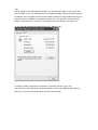
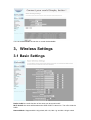
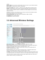
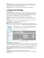
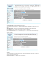
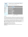
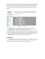
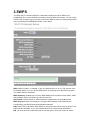
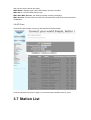
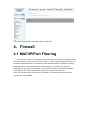
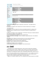
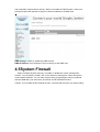
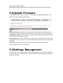
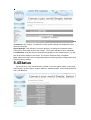
Air Pen Express Users’ Manual
Software Configuration
a. Basic Configuration
1) Look for the wireless network and connect your Air Pen express
2)Set the IP address – You can either set a static IP or enable the DHCP function. Set
your IP address through the “Internet Protocol (TCP/IP)” properties. If the DHCP server
function of your router is enabled, please select “Obtain an IP address automatically” and
then “Obtain DNS server address automatically” under the “General” tab.
Tips:
Select “Obtain an IP address automatically” only of the DHCP server of your router has
been enabled; or you can manually set the IP address instead. Please remember that the
IP address of the computer and the router should be within the same subnet and may not
share the same IP address. The default IP address is “192.168.200.1” and the subnet
mask is “255.255.255.0”; as such the IP address should not be like “192.168.200.1”.
3) You can find the assigned address under the “Support” tab:
4) Click the “Start | Programs | Accessories | Command Prompt”, type“ ping
192.168.200.1” and press Enter (as shown below). If the screen displays the following
figure, then your PC has connected to the router successfully.
5) To access the Web-based utility of the router, launch a Web browser such as Internet
Explorer or Firefox and enter the default router IP address “http://192.168.200.1” or
“pqi.air”, then press “Enter”
Congratulations, you have successfully entered the management Web page.
Quick Setup
The router supports various functions and provides a quick setup wizard. The wizard will
guide you through the basic setting process if you are not unfamiliar with the router.
(1) Click on “Next” on the right under the “Quick setting” option. This will start the router
setup procedure.
(2) This product supports 5 frequently used modes to access a network. Choose one that
suits your need. The pre-selected default mode should support the parameters provided
by your ISP; the 4 other below the default mode would require additional settings for
network connection. Please consult your ISP if you are not familiar with the parameters.
Choose one of the modes and click the “Next” button.
(3) Set a network name and an associated security encryption method for your wireless
network as shown below. Click the “Apply” button to submit your setting, and the system
will then reboot to complete the basic router setting.
Operating Modes
While the powerful Air Pen wireless broadband router series supports both “Bridge Mode”
and “Gateway Mode”, Gateway is the default mode.
Bridge mode:
The router performs as a wireless access point (AP) if the Bridge Mode has been
chosen. In the Bridge Mode, the Web-based management functions are enabled and all
RJ-45 ports on the rear panel serve as LAN ports; as such the router will function as a
switch – it will be unable to access the WAN and the firewall is disabled.
Gateway mode:
Gateway is the default mode. The NAT function will be enabled for the router to
exchange information with the Internet effectively.
Ethernet Converter:
The wireless interface will function as the WAN port while the Ethernet ports will
serve as LAN ports.
AP Client
In the AP Client Mode, the router functions as an AP that connects to other wireless
routers and establish its own wireless network. In this way, the RJ-45 ports are reserved
for the LAN. This mode is used when you need a wireless network with better coverage.
Setup process:
1. Click “Advance Settings”
2. Click “Operation Mode”
3. Select “Bridge” and set “AP Client Enabled” to “Enable” for Internet use.
4. Click “Wireless Settings”
5. Find the AP you wish to connect to in the AP list on the bottom right of the page.
Fill out the information in the form on the top right of the page.
6. Click “Apply” and connect the “Air Pen Express” to access the Internet.
2.Internet settings
2.1. WAN Connection Mode:
This router supports several common WAN connection methods. Select the method
specified by your network operator as well as the correct configuration (likely provided by
your ISP as well) to establish a working Internet connection. If you use “dynamic ”dial-up
connection such as 3G or PPPoE, there are two ways to verify the working condition of
your network: try browsing a Web site, or observe the status of your internet configuration.
Connecting Mode 1Static IP
On this screen, enter the network address information provided by your ISP in the “IP
Address”, “Subnet Mask”, “Gateway” and “Primary DNS Server ”fields.
IP Address:the WAN IP address provided by your ISP.
Subnet Mask:the WAN Subnet Mask value.
Gateway: the WAN Gateway address.
Primary DNS Server:the Primary DNS Server address provided by your ISP.
Secondary DNS Server: the secondary DNS Server address provided by your ISP.
Connecting Mode 2: Dynamic IP (via DHCP)
With the “Dynamic IP” Mode, your IP address may change every time you connect.
Connecting Mode 3: ADSL Virtual Dial-up (Via PPPoE)
Enter the User Name and Password provided by your ISP.
Connection Mode 4: L2TP
Select L2TP (Layer 2 Tunneling Protocol) if your ISP uses a L2TP connection. If so, Your
ISP will provide you with a set of username and password. Please fill them in the
corresponding fields.
L2TP provides two access modes:
If the L2TP service offered by your ISP uses Dynamic IP: Please select “Dynamic IP”.
If the L2TP service offered by your ISP uses Static IP: Please enter in the parameters
provided by your ISP. When you finish the configuration, click “Apply” to reboot the router.
L2TP Server IP: the Server IP provided by your ISP.
User Name: the L2TP username.
Password: the L2TP password.
Address Mode: select “Static” if your ISP supplies the IP address, Subnet Mask and
Gateway. “Dynamic” should work for most cases.
IP Address: the L2TP IP address supplied by your ISP.
Subnet Mask: the Subnet Mask supplied by your ISP.
Default Gateway: the Default Gateway supplied by your ISP.
Connection Mode 5: PPTP
If the connection uses “PPP Tunneling Protocol”, please input the following information
provided by your ISP: “Server IP Address”, “User Name” and “Password”.
PPTP provides two access modes:
If the PPTP service offered by your ISP uses Dynamic IP: please select “Dynamic IP”.
If the PPTP service offered by your ISP uses Static IP: please enter the information
provided by your ISP. When you finish the configuration, click “Apply” to reboot the router.
PPTP Server IP: the Server IP provided by your ISP.
User Name: the PPTP username provided by your ISP.
Password: the PPTP password provided by your ISP.
Address Mode: select “Static” if your ISP supplies the IP address, Subnet Mask and
Gateway. “Dynamic” should work for most cases.
IP Address: the PPTP IP address supplied by your ISP.
Subnet Mask: the Subnet Mask supplied by your ISP.
Default Gateway: the Default Gateway supplied by your ISP
2.2LAN Connection Mode
MAC Address: the physical router MAC address as seen on your local network, which is
unchangeable.
IP Address: the LAN IP address of your router (not your PC). Once you modify the IP
address, you need to remember it for the next login process of the Web-based Utility. The
default value is“192.168.200.1”.
Subnet Mask: the value is for the router to measure the network size; the default value is
“255.255.255.0”.
DHCP Server: tick the checkbox to enable the DHCP server.
IP Address Start/End: the range of IP addresses for DHCP server distribution.
Subnet Mask: set a matching subnet mask according to the initial/end IP address.
Primary DNS Server: the Primary DNS server address provided by your ISP (optional).
Secondary DNS Server: the Secondary DNS server address provided by your ISP
(optional).
Default Gateway: the Gateway address of the DHCP server in association with the
router’s LAN IP addresses. The default Gateway address is “192.168.200.1”.
Lease time: The effective time (in seconds) of the dynamic IP addresses that the DHCP
server allocates to the client hosts. The default value is “86400” (86,400 seconds = 1
day). During this time period, the server will not assign IP addresses to other hosts; you
can set your own preferred value to improve the void IP address recovery efficiency for
the DHCP server.
Static specification: you can set a scheme for DHCP to comply. Every time that DHCP
server assigns IP addresses automatically, a fixed IP address will be assigned to the
user’s device. If necessary, enter the designated MAC address and IP address.
MAC address: the MAC address of the PC that reserves a static IP address(example:
00:0C:43:80:88).
IP address: the reserved IP address for a host on the network (example:
192.168.200.1).802.11d Spanning Tree: Spanning Tree, as defined in the 802.1d
specification, is a bridge-to-bridge protocol for link management. It provides redundancy
for path ways to prevent “cycle path” from occurring. There is no default value.
LLTD: options include “Enabled”, “Disabled” and “Open”, If there is an LLTP client,
information about the router will be displayed automatically.
IGMP proxy: this inhibits occurrence of multicast floods by effectively obtaining and
controlling user information; and this helps reducing network side agreement and network
load. There is no default value.
UPNP: the router provides software for UPNP to P2P intranet connection. There is no
default value.
Router advertising: The router will send out or reply to broadcast information between
each node at a fixed cycle to indicate its existence. There is no default value.
PPPOE Relay: This function makes a local computer to dial PPPoE separately and
directly in the Gateway Mode. There is no default value.
2.3DHCP Clients
Select “Internet Settings | DHCP clients” to check the information of related computers to
which the DHCP server automatically assigns IP addresses on the LAN. The information
includes network name, MAC address, IP address and expiration time.
You can monitor the DHCP clients here
Expires in: the time length of the IP address lease.
2.4Advanced Routing
You may remotely add and customize Internet routing rules, and/or enable dynamic
routing exchange protocol with this function to add specific routing rules to a designated
host when necessary. Appropriate use of static routers on a network can reduce routing
selection problems and routing stream data overloads, and therefore increase the
transmission speed of data packets. A routing table can be setup through defining the IP
address, Subnet Mask and Gateway, while the destination IP address and Subnet Mask
are used to determine a target network/host so the router can send data packets to the
designated network/hosts through the gateway.
You can enable/disable the service to control the bandwidth.
3.Wireless Settings
3.1 Basic Settings
Radio On/Off: the radio function of the router can be turned on/off.
Wi-Fi On/Off: the router will broadcast the SSID if Wi-Fi is turned on. Turn off to hide the
SSID.
Network Mode: Supports 802.11b/g mixed, 802.11b, 802.11g and 802.11b/g/n mixed
modes.
Multiple SSID: the main Service Set Identifier, also the “name” of your wireless network.
Minor SSID: the optional minor Service Set Identifier.
Broadcast (SSID):select“ Enable” to make the device SSID visible by wireless clients.
BSSID: a 48-bit identity used to identify a particular BSS (Basic Service Set) within an
area. In Infrastructure BSS networks, the BSSID is the MAC (Medium Access Control)
address of the AP.
Channel: choose from the drop-down menu to set the channel of the wireless network;
please select Channel1 to 13or “Auto Select”.
Channel Bandwidth: select from wireless bandwidths of 20M or 20/40M.
HT TxStream: RF Transmit Stream.
HT RxStream: RF Receive Stream.
3.2 Advanced Wireless Settings
BG protection Mode: “Auto” by default; you can also select “On” or “Off”.
Beacon Interval: Set the beacon interval of wireless radio; do notalterthe default value
unless you are familiar with the setting. The default value is “100”.
Fragment Threshold: do not alter the default value unless you are familiar with the
setting. The default value is “2346”.
RTS Threshold:set the RTS threshold of wireless radio; do notalterthe default value
unless you are familiar with the setting. The default value is “2347”.
TX Power: set the output power of wireless radio. Unless you’re using this wireless router
in a really large space, you usually don’t need the 100% output power; setting it to a lower
value may enhance network security since this makes malicious/unknown users from a
distance harder to reach your wireless router.
WMM Capable: this enhances data transmission performance of multimedia contents
over the wireless network. If you are not familiar with it or not sure if it’s necessary, it’s
safe to leave this option as the default “Enable” setting.
APSD Capable: for auto power-saving service. The default value is “Disabled”.
3.3Security Settings
1.WEP Settings
The basic WEP (Wired Equivalent Privacy)encryption method usually encrypts wireless
data using a series of digital keys (64 bits or 128 bits in length).With the same keys on
each of your wireless network devices, you can prevent unauthorized wireless devices
from monitoring your transmissions or using your wireless resources.
SSID Choice: select the SSID for security configuration. This device supports
configurations of different security classes between the main SSID and the subordinate
SSID.
Security Mode: there are several different security modes available; you may choose
from “Mixed WEP”, “WPA-Personal” and“ WPA-Enterprise”.
Default Key: select a valid encryption key.
WEP Key1, 2, 3, 4:enter the WEP key; the key should be in accordance with the key
format and remain valid. The keys must be in ASCII Characters or Hexadecimal Digits.
2.WPA-PSK(Wi-Fi Protected Access)
A more recent wireless encryption. scheme designed to improve on the security features
of WEP to protect Wi-Fi networks. It employs more powerful encryption types (such as
TKIP, the Temporal Key Integrity Protocol, or AES, the Advanced Encryption Standard)
while the keys can be changed dynamically on every authorized wireless device.
WPA Algorithms: select either AES or TKIP encryption type, in which AES is stronger
than TKIP.
Pass Phrase: enter a key that must contain8-63 ASCII characters.
Key Renewal Interval: enter the key renewal period to tell the router how often the keys
will bechanges.
3.WPA2-PSK (Wi-Fi Protected Access version 2)
The scheme is more secure than Wired Equivalent Privacy (WEP) and is easy to set up as
well.
WPA Algorithms: select from key algorithms such as TKIP, AES and TKIP&AES.
Pass Phrase:enter a key that must contain 8-63 ASCII characters.
Key Renewal Interval: enter the key renewal period to tell the router how often the keys
will be changes.
4.WPA
This Authentication protocol is based on the RADIUS server and is used when a RADIUS
server is connected to the router.
Radius IP Address: IP address of the radius server.
Radius Port: the port number of the radius server.
Shared key:the encryption key for the router to acquire authentication through the
RADIUS server.
Session Timeout: the recertification time interval between the router and the server. The
default value is “3600” (seconds).
5. WPA2
This security mode is also used if a RADIUS server is connected to the router.
WPA Algorithms: key algorithms such as TKIP or AES.
Radius IP Address: IP address of the radius server.
Radius Port: the port number of the radius server.
Shared key:the encryption key for the router to acquire authentication through the
RADIUS server.
Session Timeout: the recertification time interval between the router and the server. The
default value is “3600” (seconds).
6.802.1X
This security mode is used if a RADIUS server is connected to the router. The
802.1xport-based authentication protocol is both an authentication type and a strategy for
users; the port can be either physical or logic (such as VLAN). For wireless LAN users, a
port is just a channel. The main purpose of 802.11x authentication is to check whether a
port can be used or not. If a port is authenticated successfully, you can open this port and
allow all the messages to flow through; if a port isn’t authenticated successfully, you can
keep it “disabled” to allow only 802.1x authentication protocol messages to pass.
WEP: select “Enable/Disable” WEP encryption to indicate the authentication process
between the wireless adapter and wireless router.
Radius IP Address: IP address of the radius server.
Radius Port: the port number of the radius server.
Shared key: the encryption key for the router to acquire authentication through the
RADIUS server.
Session Timeout: the recertification time interval between the router and the server. The
default value is “3600” (seconds).
NOTE: For improved security, do not use those words that can be found in a
dictionary or too easy to remember. Since wireless clients will keep the WEP key,
so you only have to input the key on each wireless client once. It’s worth the extra
effort to use a more complicated WEP key for better protection.
3.4WDS
Click “Wireless Settings | WDS” to enter the Wireless Distribution System (WDS)
interface and enable the function or select the WDS mode. The WDS setting turns on the
function on the radio equipment, establishes the WDS-trusted communications, extends
the wireless signal and enables wider wireless network coverage.
Note: to use the WDS function, all devices on the network must be WDS-enabled and
become WDS members; and the channel of each transmission point cannot be set as
“Automatic”. The same channel and same working mode are required on each
transmission point. The WDS member devices must obtain individual IP addresses on the
same network segment. If the DHCP function is needed, only which on one device can be
enabled and the others must be disabled. Using devices of the same brand (model and
series) for the best connection compatibility and sustainability possible.
All Air pen express products support 3modes: Lazy Mode, Bridge Mode and
Repeater Mode.
Lazy Mode
There is no need to enter a BSSID on the counterpart device in this mode. Since the WDS
connection is now “passive”, the other party should enter the BSSID address of the router.
This means that the WDS function of the other device can be only the non-Lazy Mode
(Bridge or Repeater Mode). Also, the WDS connection of the devices must be in the same
physical mode and they must be on the same wireless channel (not “Auto”), and they must
have the same wireless encryption type (Mix encryption types like WPAPSKWPA2PSK
are not supported). The devices must each obtain a unique IP address on the same
network, and only one device can have the DHCP function enabled as others must be
disabled.
Phy Mode: select the supported physical mode (CCK, OFDM or HTMIX), as the
same physical mode must be activated on all the connected devices.
Encrypt Type: select NONE (no encryption type). There are 3 types: WEP, TKIP
(Temporal Key Integrity Protocol) and AES (Advanced Encryption Standard); you can set
a maximum of 4different types and use these types to connect four different clients. Note:
the same encryption type must be activated on all devices to establish the connection.
Encrypt Key: input a new key after choosing an encryption type.
Bridge Mode
The Bridge Mode requires the BSSID to be entered on the other client. Since the AP
SSID of this router will be shielded, the wireless clients will not be able to identify this
router. The wired client can access the Internet through the WAN port.
Phy Mode: select the supported physical mode (CCK, OFDM or HTMIX), as the same
physical mode must be activated on all the connected devices.
Encrypt Type: select NONE (no encryption type). There are 3 types: WEP, TKIP
(Temporal Key Integrity Protocol) and AES (Advanced Encryption Standard); you can set
a maximum of 4different types and use these types to connect four different clients. Note:
the same encryption type must be activated on all devices to establish the connection.
AP MAC address: the BSSIDs of devices with WDS connection. You can enter4 different
BSSIDs to enable the one-to-many connections.
Repeater Mode
You have to enter the BSSID of the connected device. Either a wireless or a wiredclient
(not a bridge) can connect to the network in WDS mode.
3.5WPS
The WPS (Wi-Fi Protected Setup) is a standard created by the Wi-Fi Alliance for
establishing easy, secure wireless connections among clients and routers. You don’t have
to define the encryption type or the key, just set the WPS function by entering the right PIN
code or pressing the WPS/RESET button on the panel.
WPS: Select “Enable” or “Disable” to turn the WPS function on or off. The function must
be enabled before you can use the WPS button on the panel to set the PBC encryption.
The default value is “Disabled”.
WPS Summary: displaying the current WPS settings such as WPS current status, SSID,
authentication mode, encryption type and AP PIN, etc.
Reset OOB: click this button to restore all WPS configurations to the default value.
WPS Progress: there are two ways to configure WPS settings: PBC (Push-Button
Configuration) and PIN (Personal Identification Number).
PBC: select PBC or press the WPS button on the panel of the router for one second. The
WPS indicator will blink, so you can enable WPS on the client through WPS/PBC.
PIN: you must know the client PIN code to use this option. Enter the code and save it,
then use the same code on the client.
WPS Status: displaying the current WPS status; there are 3 states:
WSC Idle: the current WPS status is free.
WSC Start WSC Process: the WPS is currently sending a message.
WSC Success: client access to the AP was successful and a WPS connection has been
established.
3.6 AP Client
Click the AP Client button to bring up the interface as shown below:
Enter the password and press “Apply” to connect another wireless router of yours.
3.7 Station List
You may monitor stations associated with the AP here.
4.Firewall
4.1 MAC/IP/Port Filtering
This function is used to manage the clients connected to the router as well as to limit
the their Internet access. Please choose “Accept” or “Drop” before using this function, as
such data packages that do not match the rules will be accepted or dropped; and then
please provide the corresponding rules depending on your needs, but not all the
information is necessary. For example, if you’d like to prohibit a client with IP address
“192.168.200.146” from accessing the Internet, just choose “Accept” and
enter“192.168.200.146” for the source IP address. This function improves LAN user
security and manageability.
MAC/IP/Port Filtering: select “Enable” to enable this function. The default is “Disable”.
Default Policy: decide that packets don’t match any rules are dropped or accepted.
MAC address: the MAC address for which you’d like to define a rule.
Dest IP Address: the destination IP address to filter.
Source IP Address: the source IP address to filter.
Protocol: select a protocol for data package control.
Dest Port Range: the destination IP addresses to control; the starting port number must
not be greater than the ending one.
Source Port Range: the source IP addresses to control; the starting port number must
not be greater than the ending one.
Action: drop or accept the defined rules.
Comment: description of the rules.
4.2 Port Forwarding
Port Forwarding (port mapping) is the setting process of a virtual server to establish
mapping relations among the WAN IP address, the external port LAN server IP address
as well as the internal port and LAN server IP addresses. This function allows the WAN
user to access services such as Web, email and FTP via the LAN server. By default, the
wireless router will block all connection requests from the Internet to guarantee the LAN
security; how ever if you’d like to allow Internet users to access a certain service within the
LAN, you may set up a virtual server for this purpose.
Virtual Server Settings: enable or disable the virtual server. The default value is
“Disabled”.
IP address: IP address of the internal host to actas a virtual server, for example
“192.168.200.254”.
Port Range: server port range of the host on the internal network, for example “80”.
Protocol: select the program protocol (TCP/UDP/TCP&UDP); the default value is
“TCP&UDP”.
Comment: description for this configuration; for example “Visit 80 port. It will be forwarded
to the host at IP address 192.168.200.254”.
Current Virtual Servers in System: a list of virtual servers.
Single Virtual Server Settings: enable or disable a single virtual server. The default is
“Disable”.
IP address: the IP address of the internal host to act as a single virtual server.
Common Port: the port used to access the virtual server by clients.
Private Port: the real port opened by the virtual server.
Protocol: select a program protocol (TCP/UDP/TCP&UDP).
Comment: description for this configuration.
Current Single Virtual Server in System: a list of virtual servers.
4.4 DMZ
The DMZ host is the default virtual server, but its priority is lower than individually
defined virtual servers. When a wireless router receives a connection request from the
external network, the router scans the server list for opened port numbers. If there is a
matching port, it forwards the request to the corresponding virtual server; if there is not, it
looks for a matching DMZ host and forwards the request to it. If no suitable host is found,
the request will be abandoned. Setting the DMZ requires you enter only the host IP
address, choose “Enable” and click “Apply” to save the values.
Note: If you enable the DMZ function, the designated host will be exposed to the WAN
and potentially compromise its security. When you enable the DMZ function, make sure
the opened ports are identical to the port numbers enabled on the DMZ host.
DMZ Settings: enable or disable the DMZ function.
DMZ IP Address: the IP address of the host acting as the DMZ host.
4.5System Firewall
Select “Firewall | System Security” to enable or disable the remote management
function. You can allow or forbid a PC on the Internet to manage the router through the
router WAN IP address. You can also acceptor deny ping packages and ping requests
with the WAN filter, port scan block, SYN flood and SPI firewall functions.
Caution: If you enable the SPI firewall function, some firewall functions may stop working.
4.6Content Filtering
With Content Filtering, you can enable Proxy, Java, and ActiveX content filtering
when you’re browsing a Web page; and you can also set URL filtering rules according to
your needs (by domain name, hostname or keywords) to prohibit a LAN PC from
accessing certain Websites.
Webs Content Filter: select appropriate filtering rules; there are 3filtertypes:
Proxy: filter out Web pages offered by agencies.
Java: filter out Java codes on Web pages.
Active-X: filter out Active-X controls on Web pages.
Current Webs URL Filtrates (filters): the pre-defined URL filter rules. You can select
them and click “Delete” to remove.
Add a URL filter: the URL address to filter. Click the “Add” button to prohibit a Web site
from being accessed. The new URL filter will appear on top of the list.
Current Webs Host Filtrates: the pre-defined host filtrating rules. You can select them
and click “Delete” to remove.
Add a Host filter: the keywords of the host name to be filtered. Click the “Add” button to
prohibit access to certain Websites according the defined keywords; new keywords will
appear on top of the list.
5.Administration
5.1.Management
On the left pane, click “Administration | Management” to set options such as language,
administration account, password, current time, NTP (Network Time Protocol) and DNS
server.
Select Language: choose one of the three supported languages, and then click “Apply”.
Account: the user name for accessing this device; the default name is “admin”.
Password: the password for accessing this device; the default password is “admin”.
Enter the new user name and password, and then click “Apply”; the system will reboot and
ask for the new user name and password. In case you forget the username or password,
press and hold there set button on the rear panel for 5 seconds; the system will reboot and
revert to the default factory settings.
Current Time: the current time being displayed; clicking “Sync with host” synchronize the
router time and the host time.
Time Zone: set your time zone (for example, choose“GMT+08:00 China, Hong Kong” if
you reside in China).
NTP Server: the URL address of NTP server (for example, choose“ Asia Pacific NTP
Server” if you reside in China).
NTP synchronization (hours):the synchronization time interval with the NTP server.
5.2Update Firmware
Click “Administration | Upload Firmware” on the left pane to upgrade the firmware and
update the system startup loader program.
Update Firmware: click “Browse” to choose the latest firmware for the router and then
click “Apply” to upgrade. Upon completion of the firmware upgrade, the system will reboot.
Update Boot Loader: click “Browse” to choose the latest system loader program for the
router and then click “Apply” to update.
Important Note: Do not turn off the power or disconnect the network from the router while
the upgrade is still in progress, or the process will be interrupted and the device might be
damaged.
Note: Before upgrading your router, ensure that the file is the latest and that the
corresponding product is of same series.
5.3Settings Management
On the left pane, click “Administration | Settings Management” to save system settings by
exporting them to a configuration file. You may later restore the settings by importing the
file when necessary.
Exp
ort Settings: click “Export” to export the current system settings; the default file name
cannot be changed.
Import Settings: click “Browse” to see the directory containing the exported system
setting files; choose the file and click “Import”. The system will reboot upon completion.
Load Defaults: click this button to reset all configurations to the default values. You will
lose all previous settings of the router. The system will reboot upon completion.
Note: please save the current configurations before importing another configuration file or
restoring factory settings.
5.4Status
On the left pane, click “Administration | Status” to see the system status on this page:
SDK Version, System Uptime, System Platform, Operating Mode, Internet Configurations
and Local Network.
Appendix A: Common Troubleshooting Methods
Appendix A provides some methods to resolve problems you may encounter when you’re
installing the Air pen express broadband router and steps to analyze problems using
diagnostic tools.
If you cannot resolve the problem, please contact Technical Support.
1.Problem: the power indicator does not light up.
Solution: check if the power supply is working properly and you are using the proper
power adapter.
2.Problem: the WAN indicator does not light up when a network cable is plugged in.
Solution: check if the network cable has been inserted correctly into the WAN port.
3.Problem: the LAN indicator does not light up when a network cable is plugged in.
Solution: check if the power connector and Internet cables are working properly.
Check the connection from the cable to the port.
Check the Ethernet card has been in stalled correctly on the PC.
4.Problem: failed to open the setting Webpage.
Solution: make sure your browser (IE6+ or Firefox 1.5+) is the latest version and you have
Java installed on your computer.
5.Problem: setting altered on the management Web page cannot be saved.
Solution: make sure you have clicked “Apply” after completing configuration changes and
reloaded the page.
6.Problem: what if a user without firewall knowledge accidentally enables the firewall
function?
Solution: since router firewalls use strict rules, it’s not recommend for users without such
knowledge to explore or activate the function. If necessary, please ask someone who is
familiar with firewall settings for help.
Appendix B: Technical Terms
1. DHCP (Dynamic Host Configuration Protocol)
Dynamically allocates IP address, Subnet Mask and Gateway for hosts on the network.
2. DHCP Server (Dynamic Host Configuration Protocol Server)
A device that runs the Dynamic Host Configuration Protocol to allocate IP addresses to
DHCP clients.
3. DNS (Domain Name Server)
It resolves a domain name (like“www.yahoo.com”) into a corresponding IP address(like
“216.115.108.243”). A DNS message is distributed from the DNS server to the entire
Internet, so other DNS servers will check the domain name in the request and look up the
corresponding IP address when we visit a Web site. If this DNS server cannot find the IP
address, it will send a request to an upper-level DNS server to continue searching.
4. FTP (File Transfer Protocol)
A protocol transfer files among computers on the network.
5. HTTP (Hypertext Transfer Protocol)
A standard protocol delivers Web contents.
6. ICMP (Internet Control Message Protocol)
A protocol used to send error messages and important network information such as ping
commands.
7. IEEE (Institute of Electrical and Electronics Engineers)
An international institution specializes on defining technical standards.
8. ISP (Internet Service Provider)
Organizations that provide Internet access services.
9. LAN (Local Area Network)
Private intranet, such as home networks and internal network of small or medium-sized
enterprises.
10. MAC (Media Access Control)
MAC addresses are permanent addresses of physical devices specified by their
manufacturers. A MAC address is composed of 6 pairs of hexadecimal characters (like
“00-0F-E2-80-65-25”). Every network device has a globally unique MAC address.
11. NAT (Network Address Translation)
NAT allows several computers on a LAN to share a public IP address and shields LAN
users accessing the Internet. It’s usually used by broadband routers and plays an
important role in network security.
12. NIC (Network Interface Card)
Located in a PC, it provides a physical port for cable connection. An Ethernet NIC usually
comes withaRJ-45 port.
13. Ping
The ping command sends a message from one computer to another to check if the latter
is reachable and active. It is also a tool used to test whether a local computer can
exchange information with another on the network. The originating computer will sends a
message to a destination computer; if that destination computer receives the message, it
responds to the originating computer.
14. PPP (Point-to-Point Protocol)
A link-layer communication protocol.
15. RJ-45
A standard plug of networking devices to connect to ether net switch, a concentrator or
routers. A direct-connecting cable or a crossover cable usually makes use of this plug with
routing functions.
16. TCP/IP (Transmission Control Protocol/Internet Protocol)
A defined group of protocols, including TCP/IP.
17. Telnet
An interactive text-based program that allows a client (a computer user) to log into a
distant host (another computer) via the Internet for communications or device settings.
18. USB (Universal Serial Bus)
A serial interface used to connect peripherals such as printers or scanners to computers.
The USB interface on BR304 is provided to connect a host.
19. WAN (Wide Area Network)
A data communication network, such as the Internet, covering large demographic areas.
20. Web page
The Web files on the WWW.Every Website contains text and images hyperlinks with other
Webpages. Homepage is Web page at the top level of a site.
21. Broadcast
The activity sending data to all computers on a network.
22. Domain names
Managed by ICANN (Internet Corporation for Assigned Names and Numbers), the unique
key component of a URL that identifies a file on a Website. It is very convenient to the
average users since it replaces a corresponding IP address.
23. Ethernet
A network technology for establishing LANs using twisted-pair cable for data transmission.
Data transfer rates of Ethernet(radio frequency signals) between computers are usually10
Mbps or 100 Mbps.
24. Firewall
Technologies protecting computers or LANs from unwanted visits or malicious attacks.
25. Package
Data transferred on networks. Each package consists of data and message such as
source address (data sender) and destination address (data receiver).
26. Port
A physical interface on computers or routers to accept connectors for incoming or
outgoing data transmission.
27. Protocol
A group of rules used to manage data transmission. Interconnected devices must follow
these rules to transfer data successfully.
28. Long distance
A remote user, such as, staff members on a business trip, logging into a company
network.
29. Routes
Paths taken for data to travel between transmission points and receiving points. A router
is a device equipped with routing functions. You may plan for the Internet activities the
LAN users may need before defining routing rules.