1
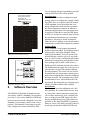
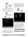
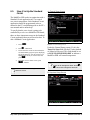
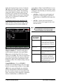
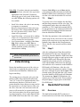
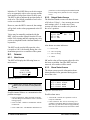
026-1720 Rev 4 06-APR-2010 MultiFlex ESR Installation and Operation Manual 3240 Town Point Drive NW Suite 100 Kennesaw, GA 30144, USA Phone 770-425-2724 Fax 770-425-9319 ALL RIGHTS RESERVED The information contained in this manual has been carefully checked and is believed to be accurate. However, Computer Process Controls, Inc. assumes no responsibility for any inaccuracies that may be contained herein. In no event will Computer Process Controls, Inc. be liable for any direct, indirect, special, incidental, or consequential damages resulting from any defect or omission in this manual, even if advised of the possibility of such damages. In the interest of continued product development, Computer Process Controls, Inc. reserves the right to make improvements to this manual, and the products described herein, at any time without notice or obligation. FCC COMPLIANCE NOTICE This device complies with Class B of Part 15 of the FCC Rules. Table of Contents 1 INTRODUCTION.......................................................................................................................................................... 1 1.1. MULTIFLEX ESR AND ESR-8 BOARD DIFFERENCES ................................................................................................... 1.1. RS-485 I/O Network ................................................................................................................................................. 1.1. Center-Tapped Transformer .................................................................................................................................... 1.1. Molex Connectors (Board P/N 810-1398) ............................................................................................................... 1.1. Hand-Held Terminal (HHT) .................................................................................................................................... 1.1. Snap-Track Mounting .............................................................................................................................................. 1.2. MULTIFLEX ESR MOLEX CONNECTOR BOARD (DISCONTINUED) ............................................................................... 1 1 1 1 1 1 2 2 INSTALLATION ........................................................................................................................................................... 2 2.1. PANEL MOUNTING AND HEAT DISSIPATION ................................................................................................................ 2 2.2. SNAP-TRACK INSTALLATION ........................................................................................................................................ 2 3 WIRING.......................................................................................................................................................................... 2 3.1. POWER .......................................................................................................................................................................... 2 3.2. VALVE WIRING............................................................................................................................................................. 3 3.2.1. Molex Connector (Discontinued) Board Wiring................................................................................................... 3 4 SETTING THE TERMINATING RESISTANCE JUMPERS ................................................................................. 4 5 SETTING THE NETWORK ADDRESS AND BAUD RATE .................................................................................. 4 6 SOFTWARE OVERVIEW ........................................................................................................................................... 5 6.1. 6.2. 6.3. 6.4. 6.5. 6.6. PROGRAMMING E2 VERSION 2.21 AND ABOVE ........................................................................................................... 6 STEP 1: ADD A MULTIFLEX ESR ................................................................................................................................. 6 STEP 2: ADD A STANDARD CIRCUIT ............................................................................................................................. 7 STEP 3: ASSOCIATE THE MULTIFLEX ESR................................................................................................................... 7 STEP 4: SET UP THE STANDARD CIRCUIT .................................................................................................................... 8 STEP 5: SET UP THE MULTIFLEX ESR ....................................................................................................................... 10 7 VALVE ZEROING...................................................................................................................................................... 12 7.1. STEP 1......................................................................................................................................................................... 12 7.2. STEP 2......................................................................................................................................................................... 12 8 HAND-HELD TERMINAL ........................................................................................................................................ 12 8.1. OVERVIEW .................................................................................................................................................................. 12 8.2. SCREENS ..................................................................................................................................................................... 13 8.2.1. Main Screen ........................................................................................................................................................ 13 8.2.2. Output Status Screens ......................................................................................................................................... 13 8.2.3. Alarm Status Screens .......................................................................................................................................... 13 8.2.4. Main Select Screen.............................................................................................................................................. 14 8.2.5. Valve Configuration Screens .............................................................................................................................. 14 8.2.6. Network Screen ................................................................................................................................................... 14 VALVE SPECIFICATIONS TABLES ............................................................................................................................15 EMERSON FLOW CONTROLS STEPPER VALVES ................................................................................................................... 15 SPORLAN (PARKER) STEPPER VALVES ................................................................................................................................ 15 MultiFlex ESR I&O Manual Table of Contents • v 1 Introduction 1.1. The MultiFlex ESR Valve Regulator board (P/N 810-3199), shown in (Figure 1-1), is an RS-485 I/O Network electronic stepper valve regulator capable of driving up to eight stepper motor valves, which are typically used to control temperature. MultiFlex ESR and ESR-8 Board Differences RS-485 I/O Network The MultiFlex ESR communicates with the E2 directly over the RS-485 I/O network, unlike the previous version of the board, which communicated with the controller over the Echelon network. Center-Tapped Transformer 10 3 9 7 8 1 2 3 4 5 Valve Connectors (8) 24VAC CT 75 VAC Power Input General Status LED I/O Network Input TX and RX LEDs 6 7 8 9 10 Termination Jumpers HHT Jack Network Address Switches Open LED (8) Close LED (8) For power, a Class 2, 80VA 24VAC centertapped transformer is required for each MultiFlex ESR board. (Previous board versions did not require a center-tapped power source.) Molex Connectors (Board P/N 810-1398) The discontinued MultiFlex ESR board’s valve outputs are four-contact molex connectors instead of the screw terminals. Valve cables having a four-contact molex connector are plugged directly into the board. This board has been discontinued and replaced with the new MultiFlex ESR board version (P/N 810-3199). Hand-Held Terminal (HHT) Figure 1-1 - MultiFlex ESR Board Layout When controlling ECT Flow valves, the MultiFlex ESR will detect overcurrent, open wire, stuck valve situations, and generate the appropriate alarms. For non-ECT Flow valves, the MultiFlex ESR will only detect overcurrent situations and generate an alarm. (See Section 8.2.3., Alarm Status Screens for details on alarm descriptions.) Set configuration parameters, setpoints, and failsafe conditions of each valve with the HHT. By using the HHT, each valve output can be set separately with a valve step rate and the total number of steps from closed to fully open. Snap-Track Mounting The MultiFlex ESR board fits into the standard CPC 4" I/O board snap-track for mounting. The MultiFlex ESR uses suction side variableposition evaporator regulators (ESRs) to vary evaporator pressure for an entire circuit and is an alternative to mechanical EPR control. The MultiFlex ESR receives input data from a CPC E2 controller (via the I/O Network) and then regulates the stepper valves according to the data from the E2. 1 • MultiFlex ESR I&O Manual 026-1720 Rev 4 06-APR-2010 1.2. MultiFlex ESR Molex Connector Board (Discontinued) 3 10 9 7 8 1 2 3 4 5 Valve Connectors (8) 24VAC CT 75 VAC Power Input General Status LED I/O Network Input TX and RX LEDs 6 7 8 9 10 Termination Jumpers HHT Jack Network Address Switches that enclosure with the MultiFlex ESR, you may need to ventilate the enclosure by installing air circulation fans or other devices to aid in heat dissipation. 2.2. Snap-Track Installation Boards not supplied with an enclosure are supplied with a snap-track for easy installation. The insulation sheet and I/O board must be removed from the track before the track is mounted. The snap-track is mounted using the 0.1875” mounting slots. Figure 2-2 shows this installation procedure: Open LED (8) Close LED (8) Figure 1-2 - MultiFlex ESR Molex Connector Board Layout Discontinued (P/N 810-3198) 2 Installation The MultiFlex ESR control board is designed to be located in a central location, preferably near the valves it is driving. Figure 2-1 shows the mounting dimensions of the MultiFlex ESR board: 4.75” TYP 2 PL 4.00” 3.5” 10.00" O 0.220” TYP 6 PL MULTIFLEX ESR BOARD WEIGHT: 9.4 OZ. Figure 2-2 - MultiFlex ESR Snap-Track Installation 9.5” 3 Wiring 3.1. Power Figure 2-1 - MultiFlex ESR Board Dimensions 2.1. Panel Mounting and Heat Dissipation The MultiFlex ESR can generate a substantial amount of heat when it draws up to a maximum of 80 VA during operation. The MultiFlex ESR is rated for a maximum ambient temperature of 65°C (150°F); therefore, depending on the size of the enclosure and what other devices are in MultiFlex ESR Molex Connector Board (Discontinued) Each MultiFlex ESR board requires a Class 2, 80VA 24VAC center-tapped transformer for power. The power connector (labeled J12) is located in the top left corner of the board. Installation • 2 CPC transformer (P/N 640-0080) is a multitapped primary transformer that may be used with the MultiFlex ESR board. the cable and cable harnesses that are supplied with the valves. Refer to Figure 3-1 and follow the instructions below for transformer power wiring: 1. Connect the three wires from the secondary side of the transformer to the power connector. The AC should be run with a minimum of 18 AWG wire up to 10 feet, 16 AWG up to 20 feet, or 14 AWG up to 30 feet. 2. Connect 24VAC to AC1 and AC2. 3. Connect the center tap (CT) of the transformer to the GND center terminal of the power connector. 4. Attach an additional 14 AWG or larger wire from the center GND terminal to solid earth ground. Keep the wire as short as possible, 6" or less is preferred, and should be completed for each board. Wire Color Legend on Each Valve Connector (8) R BLU BLK W Figure 3-2 - Valve Connector Wire Color Indicator Stepper Valve Harness BLUE BLACK RED WHITE Use 24VAC Center-Tapped Transformer WIRING FOR 640-0080, 80VA Transformer Match wire colors to silk screen legend on board terminals Power Wiring Types: 14 AWG Belden 9495 18 AWG Belden 9493 240 (HOT) L2 (NEUTRAL) 120/208/240 VAC MultiFlex ESR Board w/ Eight Screw Terminal Connectors (P/N 810-3199) L1 ECT Flow Stepper Valve C 208 PRIMARY SIDE Figure 3-3 - ECT Flow Valve and New Board Wiring Diagram 120 AC1 24VAC Center-Tapped GND AC1 GND AC2 AC2 Three-conductor non-shielded cables are the recommended wire for connecting between the center-tapped transformer and I/O boards. 24V CT 24V SECONDARY SIDE Earth ground the GND (center-tapped) terminal of each board Figure 3-1 - Power Wiring - Center-Tapped Transformer 3.2. Valve Wiring The stepper valves are wired to the board by connecting the stepper valve harness to one of the eight screw terminal connectors along the top of the board (Figure 3-3) and matching the wire colors to the legend on the connectors. Use 3 • MultiFlex ESR I&O Manual For Sporlan valves, match all wire colors except the green wire. Instead, connect the green wire to the silk screen blue wire legend (Figure 3-2). 3.2.1. Molex Connector (Discontinued) Board Wiring The stepper valves are wired to the board by connecting the stepper valve molex connector to one of the eight molex connectors along the top of the board (Figure 3-4). Use the cable and cable harnesses that are supplied with the valves. NOTE: A valve cable harness may not be longer than 150 feet. 026-1720 Rev 4 06-APR-2010 proper terminating resistance jumper settings for the MultiFlex ESR board. RS485 I/O NET JP2 JP3 JP4 TERMINATION (Jumpers in the UP position) JP2 JP3 JP4 NO TERMINATION (Jumpers in the DOWN position) Figure 3-4 - ECT Flow Valve and Old Board Wiring Figure 4-1 - Daisy Chain Termination Jumper Settings For retrofits or stepper valve harnesses without a mating molex connector, use the MultiFlex ESR adapter cable (P/N 335-3275). Crimp-type waterproof splices should be used to make the connections. For Sporlan valves used with these discontinued boards, match all wire colors except the blue wire. Instead, connect the blue wire to the Sporlan green wire. 4 Setting the Terminating Resistance Jumpers All MultiFlex ESR boards have a set of terminating resistance jumpers (one jumper for each wire lead). These jumpers are labeled JP2, JP3, and JP4 on the MultiFlex ESR board. For more information about network configuration and termination, see the I/O Network wiring section in your site controller’s user manual. CAUTION: Always have the JP1 jumper (located on the far right side of the board opposite the Termination jumpers) set to the Normal position, or the board will not operate correctly. 5 Setting the Network Address and Baud Rate Set the network address on the first five rockers of the dip switch (labeled S1) on the MultiFlex ESR board. Set the network baud rate using rockers 6 and 7. Set the termination jumpers UP (JP2, JP3, JP4) if at either end of a daisy chain. Otherwise, set jumpers DOWN. The purpose of the jumpers is to indicate the two ends, or termination points, of the segment. On a daisy chain, one device at the beginning and one device on the end must be terminated by placing all three termination jumpers in the UP position. All other devices on the daisy chain must be set to the DOWN position. Figure 4-1 shows the Valve Wiring Setting the Terminating Resistance Jumpers • 4 valve so that the advanced capabilities provided with the MultiFlex ESR will be enabled. Set the network address using the first 5 rockers of dip switch S1. Valid address range 1-31. Valve Rescaling S1 BOARD 1 2 1 3 4 5 6 BOARD 2 7 8 2 1 ON 3 4 5 6 BOARD 3 7 8 3 4 5 6 8 2 1 2 3 4 5 6 4 5 6 2 1 8 8 3 4 5 6 3 4 5 6 8 1 8 2 3 4 5 6 3 4 5 6 8 1 3 4 5 6 2 3 4 5 6 1 8 2 3 4 5 6 8 2 3 4 5 6 7 8 7 2 3 4 5 6 2 3 4 5 6 7 1 2 3 4 5 6 1 2 1 2 1 2 1 2 7 8 3 4 5 6 1 2 7 7 8 3 4 5 6 7 8 BOARD 12 7 8 2 3 4 5 6 7 3 4 5 6 7 8 BOARD 16 8 2 3 4 5 6 3 4 5 6 7 8 BOARD 20 7 8 BOARD 23 1 2 3 4 5 6 7 3 4 5 6 7 8 BOARD 24 8 3 4 5 6 7 8 ON BOARD 27 8 6 ON 1 2 3 4 5 6 7 BOARD 28 8 3 4 5 6 7 8 ON BOARD 31 BOARD 30 8 2 5 BOARD 8 7 ON BOARD 29 1 4 ON 1 8 ON 1 1 BOARD 26 1 8 6 ON BOARD 25 1 5 BOARD 19 7 ON ON 3 ON BOARD 22 7 ON 4 ON BOARD 21 2 3 2 BOARD 18 7 2 BOARD 15 7 ON 1 2 ON BOARD 17 2 ON 1 ON 1 ON 1 1 BOARD 14 7 8 ON BOARD 13 2 1 BOARD 4 7 BOARD 11 7 ON ON 6 BOARD 7 7 BOARD 10 7 5 ON BOARD 9 ON 3 ON ON 4 ON BOARD 6 7 ON 1 3 ON BOARD 5 2 1 2 1 ON 1 8 ON 2 3 4 5 6 7 8 ON Figure 5-1 - Network Address Settings Figure 5-2 - Baud Rate Settings 6 Software Overview The MultiFlex ESR board is intended to interface closely with E2’s Standard Circuit application. Once a valve on the MultiFlex ESR board has been associated with a Standard Circuit, the Standard Circuit assumes control of the valve’s position. The Standard Circuit must be specifically configured to control a MultiFlex ESR 5 • MultiFlex ESR I&O Manual The Standard Circuit has an enhanced control strategy when it is configured to control a MultiFlex ESR valve. As with previous ESR control, a PID algorithm is used to position the valve during refrigeration mode in order to maintain the circuit temperature setpoint. In addition, a minimum and maximum valve percentage may be specified. When this is used, the PID output (0-100%) is rescaled to a control range between the minimum and maximum valve percentage parameters. This may be useful in situations where the valve is slightly oversized and tends to continuously overshoot the temperature setpoint. Pulldown Mode A new Standard Circuit control state named Pulldown has been added. The Pulldown state is optional and is, by default, disabled. When enabled, the Standard Circuit will go into Pulldown following a defrost cycle or a case wash. Also, if a door switch is configured and refrigeration mode is temporarily suspended due to the door opening (such as with a walk-in box), a Pulldown will be initiated when the door closes. The Pulldown mode simply forces the valve to a fixed position, as specified with the Pulldown Percent parameter. The circuit will stay in Pulldown until the case temperature reaches the setpoint or the maximum time allowed in Pulldown has been exceeded. The maximum time in Pulldown defaults to zero, which disables the Pulldown mode. By setting this to a valid time (up to 2 hours), Pulldown mode will be enabled. Valve Failsafe The Standard Circuit has additional valve failsafe capability. If a control failure occurs, such as a loss of the control temperature sensor, the valve will be instructed to go to a failsafe position. As with previous ESR control, the valve may be configured to go to a fixed position, as specified by the Temp Fail EEPR % parameter. However, a new Valve Daily Average Position is now being calculated for MultiFlex ESR and 026-1720 Rev 4 06-APR-2010 ECT Flow valves. The valve may be configured to go to this position during periods of control failure. The Valve Daily Average Position is determined by averaging the position of the valve only during the refrigeration state. While in Defrost or other circuit states, the average position will not be updated. At midnight of each new day, the Valve Daily Average Position is updated to reflect the average position calculated throughout the previous day. In addition, if a communication failure occurs, the valve will be instructed to go to a different failsafe position (Comm Fail EEPR %) or for ECT Flow valves, the Valve Daily Average Position may be used. 3. Associate MultiFlex ESR - Assign the MultiFlex ESR to standard circuit(s) so the valve on the board is associated or "mapped" to a circuit, which will enable valve control. The association creates auto hookup of circuit valve control and alarm parameters between the circuit and the MultiFlex ESR application. This association should be completed prior to Step 4 - Standard Circuit Setup to minimize the set up of standard circuit(s) for MultiFlex ESR. 4. Standard Circuit Setup - A Standard Circuit application must be set up as normal, (with all case types, setpoints, and other parameters defined) except the Temperature Control Strategy; the Temperature Control Strategy must be set up as LINE UP(MFLEXESR)/DEF. Lead Circuit 5. MultiFlex ESR Setup - Physical properties of the valves connected to the MultiFlex ESR will need to be specified in the MultiFlex ESR application in the E2 software. When a MultiFlex ESR circuit is defined as the lead circuit in its associated Suction Group and suction float has been enabled, the Standard Circuit will suspend normal PID control of the valve while in the refrigeration state. Instead, the Standard Circuit will force the valve to full open. By doing this, the associated Suction Group will be able to float the suction setpoint to the highest possible value, while still maintaining the circuit temperature setpoint. Valve Alarms When a Standard Circuit is associated with a MultiFlex ESR valve, it also processes alarms associated with that valve, including Stuck Valve, Fault Wire, and Fault Overload. Stuck Valve and Fault Wire are only ECT Flow valve alarms. 6.1. 6.2. Step 1: Add a MultiFlex ESR A. Add Number of Boards A MultiFlex ESR board must be added to the E2 in the same manner that an 8RO or a 16AI is added in the network setup of the controller. This is done from the Connected I/O screen of the E2 (Figure 6-1): Programming E2 Version 2.21 and Above Successful installation of a MultiFlex ESR requires you to perform five main programming steps in the E2 software: 1. Add MultiFlex ESR Board(s) - The E2 refrigeration controller must be programmed to communicate and utilize the MultiFlex ESR board(s) on the network. 2. Add Standard Circuit(s) - The circuit must first be added in the E2 before a circuit can be set up and associated with the MultiFlex ESR board. Programming E2 Version 2.21 and Above Figure 6-1 - Connected I/O Screen 1. Press Software Overview • 6 2. 3. Press the down arrow key until the MultiFlex ESR field is highlighted. 4. Enter the number of MultiFlex ESRs connected to the E2 and press 5. 6.3. Press Press to save changes and exit the screen. Step 2: Add a Standard Circuit Before a standard circuit can be set up and associated with the board, you must first add the circuit in the E2 from the Add Application screen. 1. Press 2. Press 3. cally connected and can communicate. This auto hookup of circuit valve control and alarm parameters between the circuit and the MultiFlex ESR application minimizes the set up of standard circuit(s) for MultiFlex ESR (Step 4). To access the MultiFlex ESR Association screen from the Home screen: 1. Press 2. Press 3. Use the arrow keys to highlight the circuit you wish to edit, and press Choose Standard Circuit from the list (Press F4 for look-up) and use the arrow keys to move to the How Many? field. Enter the number of circuits you wish to add and press Figure 6-3 - Associations Screen Figure 6-2 - Add Application Screen 6.4. Step 3: Associate the MultiFlex ESR Each standard circuit controls a single valve. In this step, you must associate or "map" the valve on the MultiFlex ESR board to a particular circuit. When a valve on the MultiFlex ESR board is associated with a circuit, the two are automati- 7 • MultiFlex ESR I&O Manual The Circuit column displays all configured standard circuits in the E2. The MFlex ESR Appl column displays a list of all MultiFlex ESR applications in the E2 (press F4 to choose which MultiFlex ESR board to associate with the circuit). The Valve column, selectable between 1 and 8 for the valve number, displays the valve number the circuit is connected to. NOTE: A valve may be associated to only one circuit. Multiple valves cannot be assigned to a single circuit. 026-1720 Rev 4 06-APR-2010 6.5. Step 4: Set Up the Standard Circuit A. General Setup Screen The MultiFlex ESR works in conjunction with a Standard Circuit application in E2 to control case circuit temperature. Each Standard Circuit application should be programmed as documented in the E2’s installation guide or the E2’s user manual and/or online help. To specify that the case circuit is going to be controlled by a valve on a MultiFlex ESR board, there are three important screens in the Standard Circuit application that you will need to alter. To edit a Standard Circuit application: 1. Press Figure 6-4 - General Setup Screen 2. Press - CIRCUITS. Under the General Setup screen (C1 tab), the Temp Ctrl Strat field tells the E2 what method of control will be used. This field should be set to LINE UP(MFLEXESR)/DEF to indicate a MultiFlex ESR will control temperature. 3. If more than one circuit has been added, the Circuits Summary page will open, displaying all circuits in the E2. Use the arrow keys to highlight the circuit you wish to edit, and press 4. From that circuit’s Status screen, press - SETUP. NOTE: Use the F1 and F2 keys to scroll between screens. NOTE: To see all available options, view screens in the Full Options mode. Press + in E2 to turn Full Options mode ON. B. Setpoints Setup Screen Figure 6-5 - Setpoints Setup Screen Step 4: Set Up the Standard Circuit Software Overview • 8 Under the Setpoints Setup screen (C3 tab), the TR field sets the throttling range of the MultiFlex ESR temperature control. The throttling range is the number of degrees between a 0% and 100% valve aperture in the Proportional mode of PID control. In most cases, the default value (10°F) is sufficient. If a different TR is desired, enter it here. comm failure. When CommFailDefrost is set to DISABLE, the advisory priority and type can be configured: The following two advisory parameters will appear: C. Additional Setup Screen: MultiFlex ESR • Under the More Setup screen (C0 tab), set the following parameters described in Table 6-1. • AdvPrior - lets the user set the priority of the Notice or Alarm logged if a defrost is disabled due to a MultiFlex ESR comm failure. AdvTyp - lets the user select between Notice or Alarm to be logged for the event described above. NOTE: There are multiple screens under the CO: MORE tab. Use F1 and F2 to toggle between available screens under this tab. Standard Circuit Valve Parameters Min Valve % The minimum percentage the valve can go to during refrigeration control. The valve will go to 0% (fully closed) during defrost regardless of what the minimum valve % has been set to. Max Valve % The maximum percentage the valve can open during refrigeration control. Pulldown % The percentage the valve will be open during the pulldown period after defrost. Max Pulldown Tm The maximum amount of time the valve will remain in pulldown following a defrost. If exceeded, the valve will resume PID control. Pulldown will terminate earlier than the max pulldown time if the case temperature reaches setpoint. Figure 6-6 - More Tab: Additional MultiFlex ESR Setup Screen Temp Fail EEPR % - Failsafe setting that is used exclusively when the valve type (Valve Mfg) under the MultiFlex ESR Valves Setup screen is set to Other. The value set in this field will be the position the valve goes to if the case temperature sensor fails or the MultiFlex ESR board goes offline. This failsafe setting is always available. CommFailDefrost - If set to ENABLE (default), the scheduled defrost will occur if the board is in comm failure (offline). If set to DISABLE, the circuit will disable any scheduled defrost if the MultiFlex ESR board containing the valve for this circuit is in comm failure (offfline). An advisory will be logged if a scheduled defrost is disabled due to a MultiFlex ESR 9 • MultiFlex ESR I&O Manual Description Table 6-1 - MultiFlex ESR Valve Parameters - E2 More Tab 026-1720 Rev 4 06-APR-2010 Standard Circuit Valve Parameters Description Temp Fail EEPR % The MultiFlex ESR uses the value set in this field if the case temperature sensor fails. This feature is always available. Temp Fail Use Avg % If an ECT Flow valve has been selected, the MultiFlex ESR will have the option to use the daily average valve % if the case temperature sensor fails. This option is only available when valve type is set to ECT Flow. Comm Fail EEPR % The MultiFlex ESR uses the value set in this field if a communication failure with the board occurs. This feature is always available. Comm Fail Use Avg % If an ECT Flow valve has been selected, the MultiFlex ESR will have the option to use the Daily Average Valve % if a communication failure with the board occurs. This option is only available when the valve type is set to ECT Flow. CommFailDefrost If enabled (default), the scheduled defrost will occur if the board is offline (comm fail). If disabled, and the MultiFlex ESR board containing the valve associated with this circuit is in comm fail, the standard circuit will skip any scheduled defrost and an advisory will be generated. Additionally, two configurable advisory parameters will appear. Table 6-1 - MultiFlex ESR Valve Parameters - E2 More Tab 6.6. Step 5: Set Up the MultiFlex ESR Before setting up the MultiFlex ESR evaporator stepper regulator, you must have completed steps 1-4 so that the MultiFlex ESR boards are added and configured correctly in your Standard Circuit applications. In this step, you must specify the type of valves being used and (if necessary) the specifics of the valve such as step rate and maximum number of steps. ESR and press , or simply enter the number next to it. The MultiFlex ESR Summary screen will open. Figure 6-7 -MultiFlex ESR Summary Screen 4. If more than one MultiFlex ESR is listed, choose the one you wish to edit, and press 5. From the status screen, press - SETUP. NOTE: Use the F1 and F2 keys to scroll between screens. A. General Setup Screen The General Setup screen is where general properties of the MultiFlex ESR application are specified. The only field on this screen you will edit is the Name field. If you wish to assign a name to this MultiFlex ESR application, enter it in this field; otherwise, move to the Valves Setup screen. To edit a MultiFlex ESR application: 1. Press 2. Press - Configured Applications. 3. Use the arrow keys to highlight MultiFlex Step 5: Set Up the MultiFlex ESR Software Overview • 10 it, define the following fields: OvrClose% The Over Close Percentage is the percentage of the MaxStep parameter that the valve will attempt to close past its 0% limit for defrost. This will ensure the valve is fully closed when the circuit associated with the valve goes into defrost. Figure 6-8 - General Properties Screen B. Valves Setup Screen The Valves Setup screen (C4 tab) allows you to specify the type of valve connected to each output on the MultiFlex ESR board: For example, when a valve with an Over Close Percentage of 5% and a Maximum Steps value of 800 is called upon to over close (i.e., defrost), the valve will travel to the step that it counts as 0% and then attempt to close 40 more steps. By doing this, any error that may cause the valve to be slightly open at 0% will be eliminated. It is recommended that this value be set to 5% for all Emerson Flow Control valves. For more information, refer to the Valve Specifications tables at the end of this manual. Step Rate The Step Rate field corresponds to the valve manufacturer’s recommended step rate in steps-per-second. The default, 50 steps per second, is the correct step rate for the ESR 12 and ESR 20 valves. If using different types of valves, refer to the Valve Specifications tables at the end of this manual and enter the rate listed for your valve type. Figure 6-9 -Valves Setup Screen Enter specifics about the valves that are connected to the MultiFlex ESR. All valves on this screen are listed in eight rows numbered one (#1) through eight (#8). The number on each row corresponds to the similarly numbered point on the MultiFlex ESR. For each MultiFlex ESR point that has a valve attached to 11 • MultiFlex ESR I&O Manual MaxStep The MaxStep field is where you must enter the total number of steps the valve travels between fully closed (0%) and fully open (100%). This is a physical property of the valve. Refer to the Valve Specifications tables at the end of this manual to determine the total number of valve steps. 026-1720 Rev 4 06-APR-2010 Valve Mfg If you have already associated the valve and circuit, select the valve type in the appropriate field. Press the F4 button to choose the type of valve used. If this field is set to ECT Flow, the following options will be available: • • • Stuck Valve alarm - the valve is not moving in response to commands: Based on characteristics for this valve type, this feature offers a high probability that if the valve becomes stuck, a Stuck Valve alarm will be generated. Open Wire alarm - at least one drive winding of the valve is disconnected or has an open coil (no current flow was detected). Over Current alarm - available if the Valve Mfg field is either set to ECT Flow or Other, the valve driver is reporting an over current condition possibly caused by a shorted driver winding. NOTE: All alarms attempt to auto reset continuously every 10 minutes after the alarm was first detected. 7 Valve Zeroing During the installation process of the valves or when a valve is replaced, the valve(s) must be zeroed before the MultiFlex ESR board can begin controlling. The zeroing process closes the valve twice the number of Max Steps and should sufficiently "zero" ECT valves. For Sporlan and other valve manufacturers that have a full travel much greater than Max Steps, this process may need to be repeated one or two more times to fully zero the valve. Once the valve has been zeroed, the process will not need to be repeated unless the valve has been replaced or driven open beyond its control range by a device other than the MultiFlex ESR board. Note that if the valve manu- Step 1 facturer (Valve Mfg) is set to Other and the valve harness becomes disconnected while the MultiFlex ESR board is attempting to control, zero the valve after the disconnect is resolved. 7.1. Step 1 To zero the valve, first configure the Step Rate and Max Step parameters for the valve type. The configuration can be done with either the E2 controller or CPC’s hand-held terminal (HHT). For the parameters to be configured with the E2, the HHT must be unplugged and disconnected from the MultiFlex ESR board. The Max Step parameter is the total number of control steps for the valve from 0-100%, but the physical valve may have a step range that is substantially larger than the Max Step parameter. This is why the valve must be zeroed at initial start-up. 7.2. Step 2 After the configuration of Step Rate and Max Step parameters for the valve, disconnect the power plug from the MultiFlex ESR board, then reconnect the power plug to reapply power to the MultiFlex ESR board. When power has been reapplied to the board, all valves will begin to close and the Close LED (located on the right side under the valve connector on the MultiFlex ESR board) will illuminate. After the valve closes the Max Step parameter number of steps, the valve will begin to open and the Open LED (located on the left side under the valve connector on the MultiFlex ESR board) will illuminate. The moment any Open LED illuminates, disconnect power from the board. Then reconnect the power plug to reapply power to the MultiFlex ESR board. 8 Hand-Held Terminal 8.1. Overview The hand-held terminal (HHT) connector is located on the lower left side of the board and is Valve Zeroing • 12 labeled as J2. The HHT allows each valve output to be set separately with a valve step rate and the total number of steps from closed to fully open. The HHT is able to indicate the position status of each valve. The failsafe condition of each valve can be set with the HHT. However, once the HHT is removed, the settings will go back to the values programmed at the E2 if online. Valves may be manually positioned with the HHT, which overrides control from the E2 controller. Fully closing and fully opening any valve can be accomplished with a minimal number of keystrokes. The HHT can be used to fully open the valve (override to 100%) for brazing during the valve installation process or evacuation of the system. 8.2. Screens 8.2.1. Main Screen The HHT will display the following home or main screen: MULTIFLEX ESR 810-3198 VER:1.11F01 ( PRESS ) FAIL I/O NET points have not been configured (the MultiFlex ESR board is using factory defaults for valve configurations). 8.2.2. Output Status Screens The third and fourth screens will show the state of all valves. Valves 1 - 4 are seen on one screen and continue with 5 - 8 on the next. These screens will allow an override to be placed on the valve’s position. V1:C V2:0 V3:I V4:I 48% 98% NA 48% 0V:100% 0V: 5% Figure 8-2 - Output Status Screen Also shown are status indicators: • I - Valve is idle • O - Valve is opening • C - Valve is closing • A - Alarm OV and its value will not appear unless the valve has been overridden. Once the HHT has been removed, all overrides will be erased. 8.2.3. Alarm Status Screens The alarm screens provide information about alarms that have been generated during operation of the valve. Figure 8-1 - Main Screen NOTES: Press F1 at any time to return to the Home screen. Use arrows to select fields and scroll. V1: V2: V3: V4: VALVE FAULT FAULT FAULT OK STUCK WIRE OVLD Figure 8-3 - Alarm Status Screen Possible internal failures or communication bus problem messages: • FAIL: FLASH/CLK - Either the flash executable code has changed or the hardware clock is not functioning properly. • FAIL: I/O NET - Unable to communicate with the I/O Network. • FAIL: USER CFG - The MultiFlex ESR board set- 13 • MultiFlex ESR I&O Manual Possible alarm states: • VALVE OK - Normal valve operation. Valve is ready for commands. • FAULT STUCK - The valve is not moving or responding to commands: Based on characteristics for this valve type, this feature offers a high probability that if the valve becomes stuck, a Stuck Valve alarm 026-1720 Rev 4 06-APR-2010 will be generated. • FAULT WIRE - At least one drive winding is disconnected or has an open coil (no current flow was detected). • FAULT OVLD - The valve driver is reporting a shorted driver winding. 8.2.4. Main Select Screen The seventh screen (or accessed by pressing F2 on the HHT) will allow the user to select what sub-system should be accessed. (Defaults to 1.) Max Steps is the total number of steps the valve travels between fully closed (0%) and fully open (100%). SELECT: 1 Rate corresponds to the step rate of the valve (in steps per second). The default, 50 steps per second, is the correct step rate for the ESR 12 and ESR 20 valves. 1. VALVE CONFIG 2. NET CONFIG OvrCls is the Over Close percentage that will be used when setting a valve to 0% for defrost. Figure 8-4 - Main Select/Configuration Screen 8.2.5. For Valve, choose the type of valve being used. Set to ECT Flow for ECT valve types or Other for any other type of valve. Valve Configuration Screens The Option 1 screen will enable the user to view valve configurations and to make temporary changes to the settings. However, once the HHT is removed, the settings will go back to the values programmed at the E2 if online. (Defaults are Flow Control’s ESR 12 and ESR 20 valves.) VALVE:1 Other MAX STEPS: 800 RATE: 50 OvrCls Fail%: 100 5% Figure 8-5 - Valve Configuration Screens Use the up and down arrows to select the desired valve (1-8). Use the right arrow to select the desired fields. Fail % is the failsafe output percentage to use if communications are lost with the E2. 8.2.6. Network Screen The Option 2 screen will show the network settings for the MultiFlex ESR controller. There are no editable fields on this screen. This display is a reflection of the dip switch settings: DIP Settings: Address: 1 Baud : 9600 Figure 8-6 - DIP Switch Settings Screen NOTE: This Network screen can also be accessed by pressing the down arrow key once from the Home screen. • Valve: 1 - can be set to Other or ECT Flow • Max Steps - can be set from 1-10000. Default is 800. • Rate - can be set from 20-500. Default is 50. • OvrCls - can be set from 0-20. Default is 5. • Fail % - can be set from 0-100. Default is 100. Screens Hand-Held Terminal • 14 Valve Specifications Tables Emerson Flow Controls Stepper Valves TYPE ESR 12 ESR 20 Voltage 12 VDC 24 VDC Suction 50 500/800 (1) 5% 10 29 ohms 115 ohms 0 Bipolar ESR, CC100 CCB Control Step Rate Max Steps OverClose Total Watts Phase (3) Resistance Hysteresis Motor 12 VDC 24 VDC Suction 50 800 ESVB 10-20 Ton 12 VDC 24 VDC Liquid 50 800 ESVB (4) 1-4 Ton 12 VDC 24 VDC Liquid 50 (30 ok) 384 ESV (4) 12 VDC 24 VDC Liquid 30 360 (2) 5% 10 29 ohms 115 ohms 0 Bipolar ESR, CC100 CCB 5% 10 29 ohms 116 ohms 0 Bipolar CC100 CCB 5% 3.4 84 ohms 336 ohms 0 Bipolar CC100 CCB 5% 12.8 23.5 ohms 95 ohms 0 Unipolar CC100 CCB products Notes: (1) 500 steps for valves manufactured before year 2001. Identify using date code before 0100 (e.g., 0052, 9902, 9848, or brass body size ~2" vs. ~2 1/4" for 800 steps. (2) DO NOT exceed max steps of 384 for this valve. (3) Shown for 12V and 24V motors, +/- 10% at 75°F. (4) For ESV replacement with ESVB: 1. Swap the Flow Control colors RED and BLUE. 2. Cap off the YELLOW wire. Sporlan (Parker) Stepper Valves TYPE CDS-8 SEI/EEV CDS-9 12 VDC Suction 200 3064 CDS-16 CDS-17 12 VDC Suction 200 6386 Voltage Control Step Rate Max Steps 12 VDC Suction 200 1596 12 VDC Suction 200 3193/6386 OverClose Total Watts Phase (3) Resistance Hysteresis Motor 5% 10 75 ohms 10% 4 75 ohms 10% 5.7 72 ohms 10% 4 75 ohms 0 Bipolar ESR, CC100 CCB 0 Bipolar ESR, CC100 CCB 0 Bipolar CC100 CCB 0 Bipolar ESR, CC100 CCB products 15 • MultiFlex ESR I&O Manual 026-1720 Rev 4 06-APR-2010