1
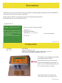
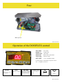
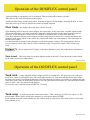
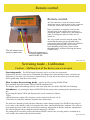
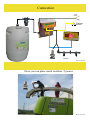
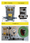
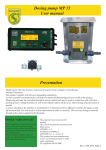
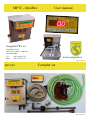
MP15 - Dosiflex
User manual
Serigstad ČR s.r.o
Pod Zámkem 105
262 03 Nový Knín - Sudovice
Czech Republic
Tel.
Mob
+420 314 003 103
+420 776 075 121
ISO 9001
www.serigstad.cz
REV.15.05.2011
Complet set
REV. 15.05.2011
Presentation
Thank you for your trust you expressed in our company by having bought the application device DOSIFLEX.
Our product meets the most rigorous regulations.
Perfect function and life can be achieved by proper assembly and maintenance.
Read instructions for use carefully before use
Serigstad ČR s.r.o.
Warning – safety above all!
Product is tested by folowing regulation
Valid safety regulations apply
to using acids and other aggressive substances.
Use protective aids enclosed
(EN50081-1,-2,
EN50011B, EN50082-1)
(EN61000-4-2, -3, -4, level 3)
2 years warranty time
EU- 89/392/
REV.15.05.2011
Connection
12 Volt DC
Fuse : 13A
CAUTION!
Cables are labelled + and Spare fuse is found inside this Power Box for the case of reversal of poles and thus interruption of the fuse.
The product can be brought into operation
by operating the main switch.
This switch can also be used if the software becomes blocked for any reason. In
such a case, turn off the main switch, wait
for 5 seconds and turn it on again.
Should lengthening of the supply cable
be necessary, use the cross-section of 2x4
REV. 15.05.2011
Fuse
Back up fuse
REV.15.05.2011
Operation of the DOSIFLEX control
Flow l/min
Output %
Tank actual
Tank total
Tank setup
OFF LINE
- Flow l/min.
- Engine load
- Tank status
- Shows total volume filled
- Tank size setup
- svití v normálním režimu
On if the pump is controlled by a superior control
unit – a computer, sensor etc.
STORE
Storing of preset values
in the memory
VIEW
Functions switching
REVERS
Functional only with DP2005
series pumps. In combination
with other pumps, provides
full performance upon holding the button
START/STOP
Switches the pump on
and off
Up
Down
REV. 15.05.2011
Operation of the DOSIFLEX control panel
Upon switching on, the display test is performed. This procedure takes about 3 seconds.
After the test, the value 00 appears on the display.
Switch on Start simply and the pump starts. Information appears on the display, showing the flow in l/min.
Press the arrow up or down to control the volume of liquid supplied.
Flow l/min – the display shows the flow volume in l/min.
If the blinking value 00 appears on the display, the pump stops. At the same time, an audio signal sounds.
This means that there is no more liquid in the tank and it must be refilled or the barrel must be replaced.
However, it can also mean a failure, such as a broken or squashed hose or faulty flow indicator.
If the flow indicator does not work anymore and the pump cannot be turned on, it can be switched in the
Output% mode using VIEW. In this mode, the pump works under any circumstances. The value stops on
the last preset value.
It is thus possible to operate in the emergency mode and continue working. The pump supplies the last
preset volume in l/min. This value is used as informative only, for possible control of the volume supplied.
Output % - Shows engine load. If failure of the flow indicator occurs, the pump can be controlled using this mode.
Tank Actual – This value shows how much liquid remains in the tank. Counts down the volume based
on the value preset as the tank volume.
REV.15.05.2011
Operation of the DOSIFLEX control panel
Tank total – volume supplied during a longer period is recorded here. The processor can count up to
1999 litres. Upon exceeding this value, the check light switches on. Tank total and the counter start counting from zero again. If an amount higher than 1999 litres must be recorded, it is possible to continue and add
1999 litres to the value on the display. In such a case, the Tank total check light is on. It means that the actual
value is 1999 + the value shown on the display.
To reset this value, hold the button STORE for 3 seconds.
.
Tank setup – Is used to preset the actual tank volume. Tank volume up to 1999 litres can be set. The
present tank volume can be stored in the memory by pressing the button STORE.
Upon holding down the button add/detract, the counter starts to count faster. The value of litres is increased
in increments of ten.
REV. 15.05.2011
Remote control
Remote control.
The left connector is used for remote control.
Attach the remote control cable to this connector.
At the end, connect the cables to the switch.
Place a mechanic or magnetic switch on the
movable part of the engine, thus stopping or
starting the pump. Control levers are used most
often, or raising the collector in the case of
cutters etc.
The left connector is
used to connect the
The very switch is used to stop the pump. This
means that the pump can be switched on by
pressing the button START/STOP, and switched
off and on again using the remote switch.
Upon finishing using of the remote switch,
the pump can be switched off using the button
START/STOP.
The right connector is
used to connect control
unit DOSIFLEX
REV.15.05.2011
Servicing mode - Calibration
Caution – Malfunction of the device can occur upon
Servicing mode – The PWM output frequency can be set in the servicing mode.
Furthermore, the flow value can be recalibrated according to the actual measured value, caused by the
difference in elevation, size of nozzles or liquid density. Is used only if the values given by the pump
differ significantly from the actual volume
How to enter the servicing mode – stop the unit by pressing START/STOP.
Press and hold down the buttons UPand DOWN simultaneously.
The display signals the blinking value 00, and at the same time, the diode ONLINE starts blinking.
Attendance – by pressing the button START/STOP, the pump starts operating at the speed preset as
last.
By pressing the button VIEW, the display mode can be switched as follows:
1 Flow
2 PWM frequency setting. The frequency can be reduced in the ratio 1:4:16
3 Time base to count flow indicator impulses (flow calibration)
The time base (amount given by the flow indicator) can be changed using UP or DOWN in the range 21
to 99 (value on the display), thus correcting the flow value, measured by the flow indicator. The value 60
corresponds precisely to the value measured according to information of the flow indicator manufacturer.
The value displayed can be changed using the buttons UP / DOWN
The setting can be stored by pressing the button STORE, whereby the servicing mode is terminated, as
well, and the unit switches into the normal mode.
REV. 15.05.2011
.
Connection
+12V
brown
Remote
switch
Nozzles
REV.15.05.2011
Here you can place metal nozzless. 2 peaces
REV. 15.05.2011