1
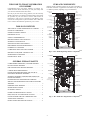
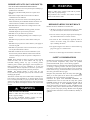
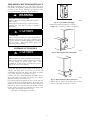
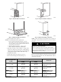
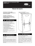
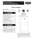
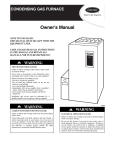
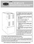
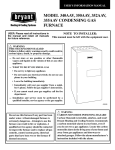
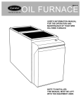
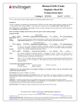
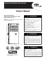
Induced Combustion Gas Furnace Owner’s Manual NOTE TO INSTALLER: THIS MANUAL MUST BE LEFT WITH THE EQUIPMENT USER. FIRE OR EXPLOSION HAZARD USER: Please read all instructions in the manual and retain Failure to follow safety warnings could result in injury, death, or property damage. WARNING ! all manuals for future reference. Do not store or use gasoline or other flammable vapors and liquids in the vicinity of this or any other appliance. WHAT TO DO IF YOU SMELL GAS --Do not try to light any appliance. --Do not touch any electrical switch; do not use any phone in your building. --Leave the building immediately. --Immediately call your gas supplier from a near by phone. Follow the gas supplier’s instructions. --If you cannot reach your gas supplier, call the fire department. Installation and service must be performed by a qualified installer, service agency or the gas supplier. WARNING ! CARBON MONOXIDE POISONING HAZARD Failure to follow this warning could result in personal injury and/or death. Carbon Monoxide is invisible, odorless, and toxic! Carrier Corp. recommends a carbon monoxide alarm in your home, even if you do not own a gas appliance. Locate the carbon monoxide alarm in the living area of your home and away from gas appliances and doorways to attached garages. Follow the alarm manufacturer’s instruction included with the alarm. A10247 C ER S I GN D DE TIFIE ISO 9001:2000 Always Ask For ! WARNING ELECTRICAL OPERATION HAZARD REGISTERED Failure to follow this warning could result in personal injury, death, or property damage. Do not use this furnace if any part has been under water. A flood--damaged furnace is extremely dangerous. Attempts to use the furnace can result in fire or explosion. A qualified service agency should be contacted to inspect the furnace and to replace all gas controls, control system parts, electrical parts that have been wet or the furnace if deemed necessary. Use of the AHRI Certified TM Mark indicates a manufacturer’s participation in the program. For verification of certification for individual products, go to www.ahridirectory.org. 1 WELCOME TO TODAY’S GENERATION OF COMFORT FURNACE COMPONENTS Congratulations! Your new, higher efficiency gas furnace is a sound investment which will reward you and your family with years of warm memories winter after winter. Not only is your new furnace energy efficient, it is also extremely reliable. Spend just a few minutes with this booklet to learn about the operation of your new furnace—and the small amount of maintenance it takes to keep it operating at peak efficiency. Years went into the development of your new furnace. Take a little time now to assure its most efficient operation for years to come. (Furnace shown in upflow position; may be used in downflow or horizontal orientation or applications. Vent Elbow may be turned to a different position, depending on type of installation) INDUCER MOTOR ASSEMBLY PRESSURE SWITCH WELCOME TO A NEW GENERATION OF COMFORT . . . . 2 MANUAL RESET LIMIT SWITCHES FURNACE COMPONENTS . . . . . . . . . . . . . . . . . . . . . . . . . . . 2 GENERAL FURNACE SAFETY . . . . . . . . . . . . . . . . . . . . . . . 2 IMPORTANT FACTS . . . . . . . . . . . . . . . . . . . . . . . . . . . . . . . . 3 MAIN LIMIT SWITCH (BEHIND GAS VALVE) BLOCKED VENT SWITCH FLUE COLLECTOR BOX GAS VALVE TABLE OF CONTENTS VENT ELBOW FLAME SENSOR GAS MANIFOLD HOT SURFACE IGNITOR GAS BURNER BLOWER DOOR SAFETY SWITCH FURNACE CONTROL BOARD SAFETY CONSIDERATIONS . . . . . . . . . . . . . . . . . . . . . . . . . 3 BEFORE STARTING YOUR FURNACE . . . . . . . . . . . . . . . . . 3 STARTING YOUR FURNACE . . . . . . . . . . . . . . . . . . . . . . . . . 4 BLOWER AND MOTOR CAPACITOR/ POWER CHOKE SHUTTING DOWN YOUR FURNACE . . . . . . . . . . . . . . . . . . 5 PERFORMING ROUTINE MAINTENANCE . . . . . . . . . . . . . 6 FILTERING OUT TROUBLE . . . . . . . . . . . . . . . . . . . . . . . . . . 6 COMBUSTION AREA AND VENT SYSTEM . . . . . . . . . . . . 8 A10259 Fig. 1 -- 80% AFUE Single Stage Furnace Components BEFORE YOU REQUEST A SERVICE CALL . . . . . . . . . . . . 8 MAINTENANCE CHECKLIST . . . . . . . . . . . . . . . . . . . . . . . . 9 INDUCER MOTOR ASSEMBLY INSTALLATION DATA . . . . . . . . . . . . . . . . . . . . . . . . . . . . . 10 PRESSURE SWITCHES GENERAL FURNACE SAFETY VENT ELBOW MAIN LIMIT SWITCH (BEHIND GAS VALVE) BLOCKED VENT SWITCH COMBUSTIBLE MATERIALS, GASOLINE WARNING. . . . 1 FLUE COLLECTOR BOX FLOOD DAMAGE WARNING . . . . . . . . . . . . . . . . . . . . . . . . 1 GAS VALVE FLAME SENSOR FIRE OR EXPLOSION HAZARD WARNING. . . . . . . . . . . . . . 1 CARBON MONOXIDE WARNING . . . . . . . . . . . . . . . . . . . . . 1 MANUAL RESET LIMIT SWITCHES FURNACE MUST BE KEPT FREE AND CLEAR OF INSULATING MATERIAL WARNING. . . . . . . .. . . . . . . . . . . 3 HOT SURFACE IGNITOR STARTING (LIGHTING) AND SHUTTING DOWN THE FURNACE WARNING . . . . . . . . . . . . . . . . . . . . . . . . . . . . . .4,5 PROPER FURNACE SHUTDOWN PROCEDURES . ......5 SERVICE AND MAINTENANCE ELECTRICAL HAZARD WARNING . . . . . . . . . . . . . . . . . . . . . . . . . . . . .. . . . . . . . GAS BURNER BLOWER DOOR SAFETY SWITCH FURNACE CONTROL BOARD 6 6 NO FILTER CAUTION . . . . . . . . . . . . . . . . . . . . . . . . . . . . . 6 FILTER ROD MODIFICATION CAUTION . . . . . . . . . BLOWER AND MOTOR CAPACITOR/ POWER CHOKE IMPROPER VENT WARNING . . . . . . . . . . . . . . . . . . . . . . . . . 6 SHARP EDGES CAUTION . . . . . . . . . . . . . . . . . . . . . . . . . . GAS MANIFOLD . . . . .7 DIRT, RUST, OR ACCUMULATION CAUTION . . . . . . . . . . . 8 FURNACE NEEDS AIR FOR COMBUSTION AND VENTILATION WARNING . . . . . . . . . . .. . .. .. . . .. . . . . . . A10260 Fig. 2 -- 80% AFUE Two--Stage Furnace Components 8 DRAFT SAFEGUARD SWITCH CAUTION . . .. . . . . . . . . . . 8 2 IMPORTANT FACTS (DO’S AND DON’TS) S DO: READ AND UNDERSTAND THIS MANUAL. S DO: Have your furnace and vent system inspected annually by a qualified service technician. S DO: Inspect your filter monthly and clean or replace when needed. S DO: Provide adequate airflow to the furnace for efficient combustion and safe ventilation. S DO: Keep your furnace free and clear of insulating material. Some materials may be combustible. Examine the furnace area when the furnace is installed or when insulation is added. S DO NOT: Enclose your furnace in an airtight room or seal it behind solid doors. S DO NOT: Keep combustible materials, gasoline, and other flammable liquids or vapors around your furnace. S DO NOT: Cover your furnace in any manner. S DO NOT: Store anything (including trash or debris) near your furnace. S DO NOT: In any way block or restrict airflow around your furnace. S DO NOT: In any way block or restrict airflow to your supply air and return air grills. S DO NOT: Use your furnace room as a broom closet or a place to store any kind of chemical or cleaner. S DO NOT: Contaminate the air used for combustion of your furnace with any kind of chemical or fumes. This could also cause heat exchangers, metal vent systems or components to deteriorate. NOTE: These chemicals or fumes are present in many products around the home, such as: water softener salts, any type of household cleaning product, any type of laundry product, adhesives, paints, varnishes, paint strippers, waxes and plastics, etc. During remodeling be sure the combustion air is fresh and uncontaminated. If these compounds are burned in your furnace, the heat exchangers and metal vent system may deteriorate. NOTE: The qualified installer or agency must use only factory--authorized replacement parts, kits, and accessories when modifying this product. This furnace contains safety devices which must be manually reset. If the furnace is left unattended for an extended period of time, have it checked periodically for proper operation. This precaution will prevent problems associated with no heat, such as frozen water pipes, etc. See “Before You Request a Service Call” section in this manual. ! WARNING FIRE OR EXPLOSION HAZARD ! WARNING FIRE OR EXPLOSION HAZARD Failure to follow safety warnings could result in personal injury, death, or property damage. Keep insulation clear of furnace and maintain clearances shown on unit clearance label. BEFORE STARTING YOUR FURNACE Examine the furnace installation to determine that: 1. All flue gas carrying areas external to the furnace (i.e. chimney, vent connector) are clear and free of obstructions. 2. The vent connector is in place, slopes upward and is physically sound without holes or excessive corrosion. 3. The return--air duct connection(s) is physically sound, is sealed to the furnace casing, and terminates outside the space containing the furnace. 4. The physical support of the furnace is sound without sagging cracks, gaps, etc. around the base. 5. There are no obvious signs of deterioration of the furnace. SAFETY CONSIDERATIONS Installing and servicing heating equipment can be hazardous due to gas and electrical components. Only trained and qualified personnel should install, repair, or service heating equipment. Untrained personnel can perform basic maintenance functions such as cleaning or replacing air filters. All other operations must be performed by trained service personnel. Observe safety precautions in this manual, on tags, and on labels attached to the furnace, and other safety precautions that may apply. . Recognize safety information. This is the safety--alert symbol When you see this symbol on the furnace and in instructions or manuals, be alert to the potential for personal injury. Understand the signal words DANGER, WARNING, and CAUTION. These words are used with the safety--alert symbol. DANGER identifies the most serious hazards which will result in severe personal injury or death. WARNING signifies hazards which could result in personal injury or death. CAUTION is used to identify unsafe practices which would result in minor personal injury or product and property damage. NOTE is used to highlight suggestions which will result in enhanced installation, reliability or operation. Failure to follow this safety warning could result in injury, death, or property damage. Do not keep combustible materials, gasoline, and other flammable liquids or vapors around your furnace. 3 STARTING YOUR FURNACE 2. Close the external manual gas valve. Your furnace uses an automatic, hot surface ignition system to light the burners each time the thermostat signals the furnace to start. CL SE O Follow these important safeguards: S Never attempt to manually light the burners with a match or other source of flame. A06188 Fig. 5 -- Close Valve 3. Turn OFF electrical supply to the furnace. A92319 Fig. 3 -- Do Not Light Burner with Match S S Read and follow the operating instructions on inside of main furnace door, especially the item that reads as follows: “Wait 5 minutes to clear out any gas. Then smell for gas, including near the floor. If you smell gas, STOP! Follow “B” in the safety information above on this furnace label. If you don’t smell gas, go to the next step.” If a suspected malfunction occurs with your gas control system, such as the burners do not light when they should, refer to the shutdown procedures on inside of main furnace door, or in the “Shutting Down Your Furnace” section and call your dealer as soon as possible. ! A92185 Fig. 6 -- Turn Off Electrical Supply 4. Remove the outer door. 1 WARNING 2 FIRE AND EXPLOSION HAZARD Failure to follow this warning could result in personal injury, death or property damage. Should the gas supply fail to shut off or if overheating occurs, turn off the manual gas valve to the furnace BEFORE turning off the electrical supply and install lockout tag. S CHECK AIR FILTER: Before attempting to start your furnace, be sure the furnace filter is clean and in place. See “Performing Routine Maintenance” section in this manual. Do not run the furnace without a filter in place. Then proceed as follows: 3 A10263 Fig. 7 -- Remove Furnace Door 5. Turn the control switch on the gas control to the OFF position and wait 5 minutes. Then smell for gas, including near the floor. If you smell gas, STOP! Follow “B” on furnace label. If you don’t smell gas, go to next step. STEPS FOR STARTING YOUR FURNACE 1. Set your room thermostat to the lowest temperature setting. ON OFF OR A02266 Fig. 8 -- Control Switch to OFF 6. After waiting 5 minutes, if you still smell gas, STOP! Follow the safety information on the cover of this manual. If you do not smell gas, go to the next step. A09564 Fig. 4 -- Lowest Temperature Setting 7. Turn the control switch to ON. 4 ON OFF 12. After about 17 seconds, the gas valve permits gas to flow to the main burners where it is ignited. Hot flames begin to warm the furnace’s heat exchanger. After a time delay of approximately 25--45 seconds the furnace blower is switched on. OR A02267 Fig. 9 -- Control Switch to ON 8. Replace the outer door. 3 2 1 A10264 Fig. 10 -- Furnace Door Replaced 9. Turn ON the electrical supply to the furnace. NOTE: If the main burners fail to ignite, the furnace control system will go through three more ignition cycles. Then if burners fail to ignite, the system will lockout. If lockout occurs or the blower does not come on, shut down your furnace and call your dealer for service. 13. Set your thermostat to the temperature that satisfies your comfort requirements. SUGGESTION: Setting the thermostat back a few degrees—and compensating for the difference with warmer clothing—can make a big difference in your fuel consumption on extremely cold days. The few degrees at the top of your thermostat “comfort level” are the most costly degrees to obtain. When the room temperature drops below the temperature selected on the thermostat, the furnace will switch on automatically. When the room temperature reaches the setting selected on the thermostat, the furnace will be automatically switched off. Continuous Fan Operation --Some thermostats have a “FAN” switch with 2 selections: AUTO and ON. When thermostat is set on AUTO, the furnace blower cycles on and off, controlled by the thermostat. In ON position, the furnace blower runs continuously except for a 42--62 sec delay at the “call for heat.” Continuous fan keeps the temperature level in your home more evenly balanced. It also continuously filters the indoor air. Comfort Fant --On all but the 58STA or 58STX, the continuous fan blower speed can be increased or decreased if desired due to change of seasons, large gatherings in your home, etc. Simply change your “FAN” switch from “on” to “off” (or “auto” depending on your thermostat), and then return to “on”, within 1 to 3 seconds. The blower will switch to the next highest speed. There are at least 3 speeds to choose from. If the blower is running on its highest speed, a request to change will direct the blower to return to its lowest speed. SHUTTING DOWN YOUR FURNACE A92359 Should you ever suspect a malfunction in your furnace, you will need to turn the furnace off. The following procedures must be followed: Fig. 11 -- Turn On Electrical Supply 1. Set your room thermostat to the lowest temperature setting. (See Fig. 3.) 10. Open the external manual gas valve. OP 2. Close the external manual gas valve (See Fig. 4). EN 3. Turn off electrical supply to the furnace. (See Fig. 5.) 4. Remove outer furnace door. (See Fig. 6.) 5. Turn the switch on the gas control to the OFF position. (See Fig.7.) A06189 Fig. 12 -- Open Valve 6. Replace the outer furnace door. (See Fig. 9.) 11. Set the room thermostat to a temperature slightly above the room temperature. This will automatically signal the furnace to start. The inducer motor will start and the hot surface igniter will energize. When hot, the igniter will have an orange glow. 7. If the furnace is being shut down because of a malfunction, call your dealer as soon as possible. 5 PERFORMING ROUTINE MAINTENANCE With proper maintenance and care, your furnace will operate economically and dependably. Instructions for basic maintenance are found on this and the following pages. However, before beginning maintenance, follow these safety precautions: ! WARNING ELECTRICAL SHOCK HAZARD Failure to follow this warning could result in personal injury or death. A92185 Fig. 13 -- Turn Off Electrical Supply Turn off electrical power supply to your furnace before removing the access doors to service or perform maintenance. ! 2. Remove filter cabinet door (See Fig. 14 and 15.) NOTE: It may be necessary to remove 1 thumbscrew. CAUTION CUT HAZARD Failure to follow this caution may result in personal injury. Although special care has been taken to minimize sharp edges, be extremely careful when handling parts or reaching into the furnace. Wear safety glasses, gloves, and appropriate protective clothing. FILTERING OUT TROUBLE ! CAUTION A06190 Fig. 14 -- Removing Side Filter Cabinet Door UNIT PERFORMANCE HAZARD Failure to follow this caution may result in product damage. Never operate your furnace without a filter in place. Doing so may damage the furnace blower motor. An accumulation of dust and lint on internal parts of your furnace can cause a loss of efficiency. A dirty filter will cause excessive stress on the furnace, heat exchanger, and blower motor and can cause it to overheat and automatically shut down. The furnace filter should be checked every 4 weeks and cleaned or replaced if necessary. If installed with factory specified disposable media filter, check or replace filter before each heating and cooling season. Replace disposable media filter at least twice a year. If your furnace filter needs replacing, be sure to use the same size and type of filter that was originally specified. The air filter for the furnace may be located in a filter cabinet attached to the side or bottom of the furnace. If air filter has been installed in another location, contact your dealer for instructions. To inspect, clean and/or replace the air filter(s), follow these steps: 1. Turn off the electrical supply to the furnace. A06191 Fig. 15 -- Removing Bottom Filter Cabinet Door 3. Slide air filter out of filter cabinet. Keep dirty side up (if dirty) to avoid spilling dirt. (See Fig. 16 and 17.) 6 A00227 A06192 Fig. 16 -- Slide Side Filter Out of Furnace Fig. 18 -- Replace Side Filter Cabinet Door A00228 A06193 Fig. 17 -- Slide Bottom Filter Out of Furnace Fig. 19 -- Replace Bottom Filter Cabinet Door 4. Inspect the filter. If torn, replace it. NOTE: If a washable filter has been replaced with: a. Factory specified disposable media filter — Do not clean. If dirty, replace only with media filter having the same part number and size. Install with airflow direction arrow pointing towards blower. b. Electronic Air Cleaner (EAC) — Refer to EAC Owner’s Manual for maintenance information. 5. Wash filter (if dirty) in sink, bathtub, or outside with a garden hose. Always use cold tap water. A mild liquid detergent may be used if necessary. Spray water through filter in the opposite direction of airflow. Allow filter to dry. 6. Reinstall clean air filter. 7. Replace filter cabinet door. (See Fig. 18 and 19.) 8. Turn on electrical supply to furnace (See Fig. 11). NOTE: If side return ducts are used, 2 filters may be required in some models. The procedure listed above may be used to remove side filters. FURNACE CASING WIDTH IN (MM) ! CAUTION PERSONAL INJURY HAZARD Failure to follow this caution may result in personal injury. Use care when cutting support rods in filters to protect against flying pieces and sharp rod ends. Wear safety glasses, gloves, and appropriate protective clothing. Filters may be field modified by cutting filter material and support rods (3) in filters. Alternate sizes and additional filters may be ordered from your dealer. FILTER QUANTITY AND SIZE * ** SIDE RETURN BOTTOM RETURN IN (MM) IN (MM) 14--- 1/2 (368) (1) 16 x 25 (406 x 635) (1) 14 x 25 (356 x 635) 17--- 1/2 (445) (1) 16 x 25 (406 x 635) (1) 16 x 25 (406 x 635) 21 (533 ) (1) 16 x 25 (406 x 635) (1) 20 x 25 (508 x 635) 24 (610) (1) 16 x 25 (406 x 635) (1) 24 x 25 (610 x 635) *Recommended **Some furnaces may have 2 filters 7 FILTER TYPE* 3/4” (19 mm) thick washable or 4--- 5/16” (110 mm) thick media--- type 3/4” (19 mm) thick washable or 4--- 5/16” (110 mm) thick media--- type 3/4” (19 mm) thick washable or 4--- 5/16” (100 mm) thick media--- type 3/4” (19 mm) thick washable or 4--- 5/16” (100 mm) thick media--- type COMBUSTION AREA AND VENT SYSTEM ! If rusty joints or seams, or signs of water leakages are found, call your dealer for service. 4. Restore electrical power to the furnace. (See Fig. 11.) 5. Start the furnace and observe its operation. If possible, watch the burner flames. Are they burning bright blue? If not or if you suspect some other malfunction, call your servicing dealer. 6. Replace the access door. (See Fig. 10.) WARNING UNIT OPERATION HAZARD Failure to follow this warning could result in personal injury or death. For proper and safe operation the furnace needs air for combustion and ventilation. Do not block or obstruct air openings on the furnace, air opening to the area in which the furnace is installed, and the space around the furnace. ! WARNING CARBON MONOXIDE POISONING HAZARD Failure to follow this warning could result in personal injury or death. If holes are found or if the vent pipe is obstructed or is not connected, toxic fumes can escape into your home. DO NOT OPERATE YOUR FURNACE. Call your dealer for service. Inspect the combustion area and vent system before each heating season. An accumulation of dirt, soot, or rust can mean a loss of efficiency and improper performance. Buildups on the main burners can cause faulty firing. This “delayed ignition” is characterized by an alarmingly loud sound. NOTE: If your furnace makes a loud noise when the main burners are ignited, shut down the furnace and call your servicing dealer. Use your flashlight and follow these steps for inspecting the combustion area and vent system of your furnace: 1. Turn off electrical supply to the furnace and remove the access door. (See Fig. 6 and 7.) 2. Carefully inspect the gas burner for dirt, rust, or scale. Inspect the elbow, flue connection area, and the vent pipe for rust. BEFORE YOU REQUEST A “SERVICE CALL” Before you call for service, check for several easily solved problems: S Check for sufficient airflow. Check the air filter for dirt. Check for blocked return--air or supply--air grilles. Be sure they are open and unobstructed. If this isn’t the cause of the problem, call your servicing dealer. If your furnace isn’t operating at all, check the following list for easily solved problems: S Is your thermostat set above room temperature? Is the HEAT mode selected? S Is the electrical power supply switch on? Is the blower access door firmly in place? Are any fuses blown? (There is a fuse on the furnace control.) Has a circuit breaker tripped? S Is the manual shut--off valve in the gas supply pipe leading to the furnace open? Does the lever point in the same direction that the pipe runs (open)? Or is it at a right angle to the pipe (closed)? NOTE: Before proceeding with the next checks, turn off the electrical power supply to the furnace. Remove access door. S Is the switch on the gas valve turned to the ON position? If this or the preceding check shows an interruption in the gas supply, make sure the gas has not been shut off for safety reasons. If nothing else seems to be wrong, follow the start--up procedures found on pages 4 and 5 of this booklet. ! CAUTION PERSONAL INJURY HAZARD Failure to follow this caution may result in personal injury. If for some reason the vent is blocked, the draft safeguard switch will shut off the furnace. (See Page 2 for switch location.) The switch will automatically reset after the furnace cools off. If the furnace fails to operate, contact a qualified service agency. A92330 Fig. 20 -- Burner Flame ! WARNING CARBON MONOXIDE POISONING HAZARD Failure to follow this warning could result in personal injury or death. If dirt, rust, soot, or scale accumulations are found, call your dealer. Do not operate your furnace. S Check the manual reset limit switches located on the ends of the burner enclosure (see Fig. 1 and 2). If the furnace has experienced a high--temperature condition due to inadequate combustion air, these switches will shut off the furnace. Reset the switches by pushing the button on the switch. If the switch trips a second time, turn off the furnace and call for service. S If your furnace still fails to operate, call your servicing dealer for troubleshooting and repairs. Tell your dealer the model and serial numbers for your furnace. (You should have them recorded on page 10 of this booklet.) By knowing exactly which furnace you have, the dealer may be able to offer suggestions over the phone or save valuable time through knowledgeable preparation for the service call. 3. Inspect the vent pipe for a sag, holes, or a disconnection. A horizontal vent pipe must slope upward away from furnace. 8 In addition to the type of routine maintenance you might be willing to perform, your furnace should be inspected regularly by a properly trained service technician. You should work with your dealer or service technician to assure your inspection includes the following at a minimum. MAINTENANCE CHECKLIST INSPECTION INTERVAL DESCRIPTION Monthly Bi-annually Annually Furnace specific, external items: Clean or replace air filters. X Inspect cabinet for signs of damage. X Inspect and clean door louvers if needed. X Inspect electrical disconnect for proper function. Repair or replace as necessary. X Inspect external wiring for damage. X Inspect gas supply line and manual shut-off for leaks. X Furnace specific, internal items: Inspect and clean blower assembly (includes blower housing, blower wheel and motor). X Inspect gas valve and check for proper manifold gas pressure Adjust as needed. X Inspect ignition system and safety controls. Clean and adjust as needed. X Inspect control box, associated controls, wiring and connections. X Check combustion blower housing for lint and debris and clean as necessary. X Inspect burner assembly - clean as needed. X Inspect heat exchanger - clean as needed. X Inspect flue system—check for proper attachment to the furnace, any dislocated sections, and for signs of corrosion. Replace if necessary. X System: Inspect airflow system (ductwork)—check for leaks and repair as needed. X Inspect evaporator coil, drain pan and condensate drain lines as applicable. Clean as needed. X This list may not include all maintenance items, and inspection interval times may vary depending on operational conditions of the furnace. Ask your servicing dealer for further details about an economical service contract that covers seasonal inspections. 9 NOTE TO EQUIPMENT OWNER: For your convenience, please record the model and serial numbers of your new equipment in the spaces provided. This information, along with the installation data and dealer contact information will be helpful should your system require maintenance or service. FURNACE INSTALLATION INFORMATION: Model # _____________________________________ Date Installed ________________________________ Serial # ______________________________________ DEALERSHIP CONTACT INFORMATION: AIR CONDITIONER OR HEAT PUMP Company Name_______________________________ Model # _____________________________________ Address______________________________________ Serial # _____________________________________ _____________________________________________ INDOOR COIL (Furnace Coil or Fan Coil) Phone Number _______________________________ Model # _____________________________________ Technician Name _____________________________ Serial # _____________________________________ _____________________________________________ _____________________________________________ NOTE TO INSTALLER: This manual must be left with the equipment owner. HEATING & COOLING TO OBTAIN INFORMATION ON PARTS: Consult your installing dealer or classified section of your local telephone directory under the “Heating Equipment” or “Air Conditioning Contractors & Systems” heading for dealer listing by brand name. Carrier Corporation S Indianapolis, IN Have available the Model No., Series Letter, & Serial No. of your equipment to ensure correct replacement part. 46231 Copyright 2010 Carrier Corporation Printed in the U.S.A. Edition Date: 08/10 Manufacturer reserves the right to change, at any time, specifications and design without notice and without obligation. 10 Catalog No: OM58 ---131 Replaces: OM58--- 126