1
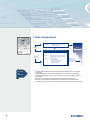
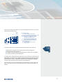
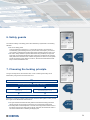
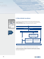
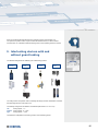
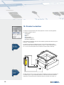
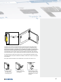
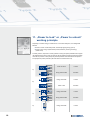
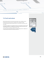
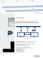
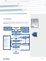
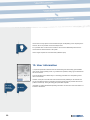
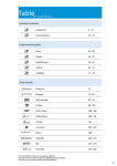
Design of safety guards Under observation of ISO 14119 Introduction With the Machinery Directive (MD) 2006/42 / EC and its associated standards, the European Union has created a set of rules that needs to be considered when designing machinery and plants. This set of rules is also considered and adapted in markets outside the EU as a basis for machine safety. It contains amongst other statements concerning the design of the moveable safety guards. Position monitoring of moveable guards is described in detail in ISO 14119 "Safety of machinery - Interlocking devices associated with guards - Principles for design and selection" (German version: DIN EN ISO 14119: 2013). This new standard replaces the currently valid EN 1088 and was published on 11 April 2014 in the Official Journal of the European Commission as an European standard harmonised under the MD. As an ISO standard, it is also valid beyond the European Union. Since the transition period for the implementation of the new standard ends on 30 April 2015, you should already consider this standard during the design of new machines and plants. This brochure's objective is to aid designers of machinery and plants with standard-compliant design of moveable guards taking into consideration the ISO 14119 and other relevant regulations. In the centre of the brochure there is an accompanying poster, that gives a quick overview of the technically correct design of moveable safety guards and represents the whole process of their standard-compliant selection and design in the form of a flowchart. This brochure outlines the enclosed poster and gives detailed information on the individual process steps of the flowchart. The page numbers noted on the poster refer to the relevant page in this brochure, where the process step is described. The contents of this brochure reflect the interpretation of the Schmersal Group and is also based on the experience gained as a member of the Deutschen Institut für Normung e.V. (German institute for standardisation), Standards Committee NA 095 Safety principles and "Protective devices, safety measures and interlocks". Reading the brochure does not exempt you from your own study and interpretation of the standard. An initial note on terminology: The term "interlocking device" used in the standard is synonymous for safety switchgear and often leads to confusion, because the term "interlocking device" is generally associated with a component which actually does keep the safety guard locked. From the standard’s point of view this component is referred to as interlocking device with guard locking. The interlocking devices themselves, by definition of the standard, only monitor the position (open / closed) of the safety guard. This task can be fulfilled by electromechanical safety switches or non-contact safety sensors. 2 Content Introduction ___________________________________________________________Page 02 1. Risk assessment ____________________________________________________Page 04 2. Inherent safety ______________________________________________________Page 05 3. Technical protective measures __________________________________________Page 05 4. Determination of the safety function______________________________________Page 06 5. Design of the safety circuits ____________________________________________Page 08 6. Safety guards _______________________________________________________Page 09 7. Choosing the locking principle __________________________________________Page 09 8. Rate defeat incentives ________________________________________________Page 10 9. Interlocking devices with and without guard locking __________________________Page 15 10. Product selection____________________________________________________Page 16 11. Interlocking devices with guard locking with “Power to lock” or “Power to unlock” working principle _______________________Page 18 12. Fault exclusions to ISO 13849-2 _______________________________________Page 19 13. Verification ________________________________________________________Page 20 14. Validation _________________________________________________________Page 21 15. User information ____________________________________________________Page 22 16. List of Standards ____________________________________________________Page 23 3 1. Risk assessment Risk assessment (based on the defined limits and the intended use of the machine) User information Risk Protective measures to be made by the designer: Designer information ISO 12100: Risk assessment 4 Step 1: Inherently safe design Step 2: Technical protective measures and supplementary protective measures Step 3: User information • on the machine - Warning signs: Signals - Warning equipment • in the user manual Residual risk after the measures taken by the designer ■ The MD and therefore the law requires each machine manufacturer to carry out a risk assessment. ■ The risk assessment consists of hazard identification, risk estimation and evaluation. ■ The risk assessment takes into account the entire life cycle and all operating modes of the machine. ■ Instructions for conducting a risk assessment can be found in the ISO 12100. ■ Only after completing the risk assessment the manufacturer knows where there are possible risks of injury on the machine and whether anything needs to be done about them. 2. Inherent safety a Minimum distances Limiting the effective energy Interrupting the flow of power Elastic deformation Forces that occur at the hazard spot are to be deliberately limited so as not to have any bodily damaging effect The buildup of forces that would lead to injuries is reliably interrupted before reaching the limits Deliberately resilient machine parts which deform and absorb most of the deforming energy a Dangerous movements stop at a distance that cannot deform limbs ■ According to the image of the ISO 12100, the risks must be constructively eliminated first (= Inherent safety); see ISO 12100, section 3.20. ■ Inherent safety is understood to mean the elimination of risks by constructive measures. 3. Technical protective measures ■ If the identified risks cannot be eliminated by design measures, or at least minimised to an acceptable level, technical protective measures must be taken such as optoelectronic protective equipment, tactile protective devices, two-hand controls etc., refer to ISO 12100, section 3.21. ■ Such a technical protective measure could for example be a movable safety guard. This brochure concentrates on such measures. 5 4. Determination of the safety function ■ Table 8 of ISO 13849-1 defines safety functions that ensure that the identified risk is minimised, also see ISO 12100, section 30.3. ■ When implementing safety functions, the entire safety circuit must be taken into consideration - starting with the sensors (input, in our case the interlocking device), the monitoring device (logic) and the actuator (output). Every safety function or circuit includes the following components (Sub-systems): ISO 13849-1: Safety function I nput Logic for example: ...or... ...or others 6 Output By using the risk graph of ISO 13849-1, Annex A, the required performance level (= PLr) can be determined for this safety function. Low risk F1 S1 S2 F2 Starting point for estimating the risk reduction a P1 P2 F2 F1 Required performance level PLr P1 P2 b P1 P2 c d P1 e P2 S Severity of injury S1Slight (normally reversible injury) S2Serious (normally irreversible injury or death) FF Frequency and / or exposure to hazard F1rarely up to less often and / or time of exposure to the hazard is short F2Frequently up to permanently and / or time of exposure to the hazard is long P Possibility of preventing the hazard or limiting the damage P1 possible under certain conditions P2 barely possible High risk The relevant safety functions of movable safety guards are (see ISO 14119, section 3.2): ISO 14119 Safety function ■S witching off the dangerous machine function when opening the safety guard ■ Protection against unexpected start-up ■ If necessary, locking the safety door until the dangerous machine function is completed ■ If necessary unlocking the guard locking device The safety function "unlocking the guard locking device" is new. However, the standard assumes (see remarks 1 and 2 of section 8.4.), that the PL of the locking device is less than the PL of the interlocking device. Reason: "The probability of the failure of the interlocking and simultaneous access of a person is very low." (ISO 14119, section 8.4, Note 2.). Nevertheless, inadvertent unlocking of the locking device must be included in the risk assessment. ISO 14119 takes into account the characteristics and requirements on the sensor (input) of the safety circuit. Their sensor is part of the interlocking device of a safety guard described in the standard. 7 5. Design of the safety circuit After the safety function has been determined, it is now necessary to design the appropriate safety circuit. The design is to be in accordance with the requirements of the PLr (see ISO 13849-1, section 6). This means it must meet the requirements of the: ■ structure of the safety circuit L O L TE Categories B and 1 I1 O Second shutdown path OTE or reporting path Category 2 Monitoring Input signal L1 I2 Input signal O1 Output signal Short-circuit recognition I I Output signal Monitoring ISO 13849-1: Safety architecture Output signal Monitoring Input signal Monitoring Input signal Monitoring Monitoring L2 Output signal O2 Categories 3 and 4 ■ expected service life of the components used until the first occurrence of a dangerous fault: MTTFd (or B10d) ■ test quality, which means the quality of the dangerous fault detection: DCavg ■ measures against common cause failures: CCF Note to DCavg ■ In many applications, the interlocking devices are electrically connected in series. Because of the possibility that dangerous faults that occur may not be detected the DCavg must be correspondingly reduced. ■ A technical report currently being prepared (ISO/TR 24119) will give relevant information on series connections of interlocking devices and their effect on the DCavg. Currently, we recommend that you set the following DCavg: ■ Series connection of interlocking devices with positive break contacts: DCavg = 60% (which still allows a max. performance level of PL d) ■ Series connection of magnetic interlocking devices: DCavg dependent on distance of the safety guards and their frequency of operation ■ Series connection of self-monitoring electronic interlocking devices: DCavg = 99% (which allows a max. performance level of PL e) ■ Further details on these values, see our information sheet "Estimation of diagnosis degree in series connections of electromechanical safety switches and safety sensors" under http://series-connection.schmersal.net 8 6. Safety guards The mechanical design of the safety guard is also described by requirements in the following standards: ■ ISO 14120: Safety guards There is a reference in section 6.4.4.1 on the access or frequency of access with a movable safety guard indicating when they are to be used. At a frequency of more than once a week a movable guard should be used with an interlocking device to ISO 14119. ■ ISO 13857: Safety distances to prevent hazard areas being reached by the upper and lower limbs. This standard describes the sizes of limbs and consequently the necessary safety distances to hazardous areas. It states amongst others in section 4.3, that guards should not exceed a ground clearance of 180 mm, because this would allow the whole body to access the hazardous area. ISO 14120: Safety guards ISO 13857: Safety distances 7. Choosing the locking principle The type of locking device, that should be used, i.e. with or without guard locking can be determined by using the flow chart of the ISO 14119. Start Overall system stopping performance ≥ entry / access time Yes No Interlocking guard with guard locking (see section 5) Interlocking guard without guard locking can be sufficient (see 5.1 to 5.6) ISO 14119: Locking principle End Information to answer the question whether the stop time of the whole system is ≥ entry / access time is given in the standard ISO 13855 section 9. ■T his given standard calculates the safety distance from behind the safety guard to the danger zone with an entry speed of 1600 mm/s or an access speed of 2000 mm/s. ■T he safety distance is also dependent on the size of the body parts that obtain access to the danger zone when the safety guard is opened. Therefore, the standard ISO 13857 is also to be considered when calculating the stopping time. ISO 13855: Entry and access speed 9 8. Rate defeat incentives An investigation has showed that accidents are often the result of protective equipment being defeated. Therefore an essential focus of ISO 14119 is the prevention of the interlocking devices from being tampered with. To prevent this the standard suggests a certain method in the form of a flowchart. Start Implementing basic measures (see 7.1a) ISO 14119: Manipulation incentives Is there an incentive to bypass? (see 7.1b and annex H) Yes Is it possible to eliminate or to minimise the incentive to bypass interlocking devices (see 7.1c) No No Implementation of measures against a "bypass on reasonably foreseeable manner" required by Table 3 (see 7.1c) Yes Elimination of minimising the incentive to bypass by implementing design measures or alternative operating modes (see 7.1c) End The goal of this method is to recognise the defeat incentive and to reduce or eliminate it. The ISO 14119 also supports the designer with determining the defeat incentive. It suggests a matrix that shows the task to be carried out on the machine and the consideration of easing the task through corresponding defeat. 10 … Prevention of interruptions b Better flow of movement b Larger freedom of movement b Less travel b Less physical effort b Improved audibility b Improved visibility b Higher level of precisionb Quicker / high productivityb Easier / more convenient b Tasks possible without bypassing? Allowable tasks for this operation mode? Operating mode 5a Operating mode 4 a Operating mode 3a Operating mode 2a Operating mode 1a Task Flexibility, such as with larger work pieces Thus, it is readily apparent, at what point and in which task or operating mode of the machine there is a risk of defeat. Commissioning Program test / Test run Installation / adjustment / modifcation / equipping Proccessing Manual intervention for removal of debris Manual changing of work-pieces Manual intervention with troubleshooting Check / random sampling Manual intervention with measurement / fine adjustment Manual tool change Maintenance / Repair Fault rectification on machine Cleaning, e.g. removing debris Tab. 2 Example of an assessment of incentives to bypass interlocking devices (Source: ISO/DIS 14 119, Table H.1). Of course, this table is to be adapted to the respective application or machine. 11 B A primary hazardous area C D If it is determined that defeat incentives exist, then these must first be eliminated by design, see ISO 14119, section 7.1 c. Examples of purely constructive measures are: A) E rgonomics: - Height adjustment of the control panel - Arrangement and design of the display and operating elements - Position of the emergency stop switch - Observability of the working zone - Dimensions and location of the handles - Manual forces for displacing B) Viewing window: Window construction: Polycarbonate - window must be protected against chemical and abrasive influences from inside with a safety glass pane and from the outside should be protected with a non-splintering plastic pane or splintering prevention foil. Window mounting: The mounting should be able to withstand high impact reaction forces, allow considerable deforming and at the same time the ends of the polycarbonate window should be hermitically sealed against chemical reaction. C) Protective cover: Cover structure: With sandwich construction, the inner skin must be extremely deformable, and the outer skin designed to be extremely resistant and stiff. Main closing edge: With power-operated safety doors the kinetic energy and speed when closing must be limited so that no dangerous pinching point is created at the main closing edge. The effective closing force must not exceed 150 N. Cover mounting: Guidance on rollers in form-fitting custom runners. Clamps prevent ejection of the cover if damaged. The lower area of the cover should be designed that neither debris nor cooling lubricant can escape outwards. D) Controllers: Functional safety: Reliable fulfilling of safety functions within a defined period of time with the safety relevant part of the controller. Defeat prevention: Interlocking elements non-accessibly mounted with tamperproof screws if necessary. Safety concept harmonised with activity in all service life stages of the machine. 12 Key transfer systems (with middle and high coding level, see note 2) Type 2- and Type 4-Interlocking devices with high coding level according to 7.2 b) 3) with or without solenoid latching! Type 2- and Type 4-interlocking device with low or middle coding level according to 7.2 b) 1) or 7.2 b) 2) with or without solenoid latching Type 1-Interlocking device (operated only with hinge) Type 1-Interlocking device (except when hinge-operated) and Type 3-Interlocking devices Principles and measures ISO 14119: Schedule 3 Mounting out the reach, see 7.2 a) 1) Barrier / shielding, see 7.2 a) 2) X Mounting in hidden location, see 7.2 a) 3) Condition monitoring or periodic examination, see 7.2 d) 1) i) and ii) X Non-releasable attachment of position switches and actuators, see 7.2 c) Non-releasable attachment of the position switch, see 7.2 c) M Non-releasable attachment of the actuating element, see 7.2 c) M Additional interlocking device and plausibility checks, see 7.2 d) 2) R M M M M R X The application of at least one of these measures is mandatory M Mandatory measure R Recommended measures (additional) 13 ISO 14119: Fixing In ISO 14119 section 5 very general requirements for the installation and mounting of interlocking devices are described which must be observed regardless of the measures described in Table 3 above: Section 5.2: Arrangement and mounting of position switches Position switches must be arranged so that they are adequately secured against their position be changed. To achieve this, the following requirements must be met: ■ The fasteners of the position switches must be reliable and to remove them, a tool is required. ■ Type-1-position switches must have a method to permanently secure the position after adjustment (such as bolts or dowel pins). ■ The facilities required for access to the position switches for maintenance and verification of the correct operation must be ensured. Avoidance of dealing in reasonably foreseeable way is also to be considered when designing the access. ■ Gradual loosening must be prevented. ■ Bypassing the position switch in a reasonably foreseeable way must be prevented (see section 7). ■ The position switches must be arranged and, if necessary, be protected in such a way to prevent damage by unforeseen external causes. ■ The movement caused by the mechanical operation or the distance to the actuating system of a non-contact position switch must remain within the actuating area of the position switch specified by the switch manufacturer or the actuating system, this is to ensure proper operation and/or to prevent an overrun. ■ A position switch should not serve as a mechanical stop, unless this is the intended use of the position switch according to the manufacturer. ■ Misalignment of the guard, caused by an opening before the position switch state changes should not affect the protective effect of the safety device (regarding access to hazardous areas, see ISO 13855 and ISO 13857). ■ The receptacle and the mounting of the position switches must be sufficiently stable to maintain proper operation of the position switch. Section 5.3: Arrangement and mounting of actuators Actuators must be secured so that the possibility of becoming loose or the possibility of modifying its intended position relative to the actuating system is reduced to a minimum over the intended service life. ■T he fasteners of the actuators must be reliable and to move them, a tool is required. ■ Gradual loosening must be prevented. ■T he actuators must be arranged and, if necessary, be protected in such a way to prevent damage by unforeseen external causes. ■A n actuator should not serve as a mechanical stop, unless this is the intended use of the actuator according to the manufacturer. ■T he receptacle and the mounting of the actuator must be sufficiently stable to maintain proper operation of the actuator. 14 Given the procedure described above and the protective purpose of this standard, it is our opinion that a position switch may be mounted with standard screws, if neither a defeat incentive exists, nor a standard screwdriver belongs to the normal operating tool of the machine. 9. Interlocking devices with and without guard locking The standard distinguishes four different types of interlocking systems: Type 1 uncoded Type 2 coded Type 3 uncoded Type 4 coded The coding level is not important. When considering the designs, the first consideration is whether the interlocking device is at all coded or not. The following coding levels are defined in the standard (see section 3.13.1 to 3.13.3): Coding options: 1 - 9 low: medium: Coding options: 10 - 1,000 Coding options: > 1,000 high: This definition is independent of the locking function of the interlocking device. 15 10. Product selection The selection of the appropriate product always depends of course on the real application, i.e. operating conditions, such as: ■ Temperature ■ Humidity ■ Dirt ■ Shock/vibration ■ Explosive atmosphere ■ Necessary holding force Further details and application instructions for the different types described above are given in annexes A - F of the standard. ISO 14119 / ISO 13849-2: Redundancy The selection of a product also depends on the PLr to be achieved (see above page 7). ISO 14119 and ISO 13849-2 prescribe redundancy of Type 1 or Type 2 switches when the PLr = PL e is to be reached (see ISO 14119 section 8.2 and ISO 13849-2, table D.8). 1121 1222 1121 IEC 60947-5-3: Product standard of safety sensors 16 1222 If a safety sensor (Type 3 or Type 4) is being used - that allows to use only one to achieve PL e in contrast to Type 1 or Type 2 switches (see above) - make sure that this sensor fulfills the requirements of the product specific standard IEC 60947-5-3 (see ISO 14119 section 5.4) (3) GY S11 (1) GN S21 (5) WH S31 S12 PK (4) S22 YE (2) S32 BN (6) If, because of the stopping time described above, an interlocking device with guard locking is required, then Annex I is to be observed. It informs about the maximum possible static action forces that may be posed on interlocking devices with guard locking feature. As an informative annex and as an exemplary enumeration it is to be understood as a guideline of possible maximum force levels (ie: orders of magnitude) are represented. The locking forces actually required in a real application cannot and will of course not be prescribed by the standard. Here, either the machine manufacturer or a type C standard (also see section 6.2.2 Note 2) should be consulted. If an interlocking device with a guard locking is used, a manual (deliberate) deactivation of the guard locking device should be considered for installation, maintenance or repair work purposes on the machine. Such types of release are defined in the standard ISO 14119 section 3.25 to section 3.27: ■ Emergency release: mounted outside the hazardous area, for emergency use ■ Auxiliary release: for unlocking during setup, no emergency ■ Escape release: mounted within the hazardous zone to be able to leave the area independently in the event of danger 17 11. „Power to lock“ or „Power to unlock“ working principle Depending on whether energy is needed to lock or unlock the safety door, one distinguishes between ■ Power to unlock: mechanically locked, unlocked by applying energy (see A) ■ Power to lock: energy required to keep locked, release by removing the energy (see B and D) For safety reasons, the power to unlock (quiescent current) principle is preferable. After a proper risk assessment the power to lock principle may also be applied. Accordingly interlocks are often used with the power to unlock principle for personal protection and interlocks with the power to lock principle for process protection (also see section 3.28 and section 3.29) Power to unlock Locked Energy ON unlocked Unlocked Energy ON locked Locked Power to lock Unlocked Energy ON locked Locked Energy ON unlocked Unlocked Energy ON locked Locked A) B) C) D) 18 12. Fault exclusions Machine safety requires the correct functioning of the safety circuit. It is therefore of utmost importance that any errors that could occur leading to a loss of safety are excluded. The central standard that deals with possible errors in the components of a safety circuit, is the ISO 13849-2. In the annexes, possible errors and possible exclusions due to the application of certain tecniques are described in tabular form. For example: The non-opening of an electro-mechanical contact can be excluded by using a switch with positive break contacts. It is important to study the applicable tables of the standard (especially Annex D: Validation tools for electrical systems) and document possible fault exclusions. ISO 13849-2: Fault exclusions 19 13. Verification The verification is used to provide evidence that the selected components and their interconnections are sufficiently resistant to systematic and random errors that would result in the loss of the safety function. This is accomplished using a PL-calculation that must also include the corresponding monitoring device and the actuator. This calculation process is described in ISO 13849-1. Calculation of the safety function Input ISO 13849-1: Verification Logic Structure = Category 3 = 2,000,000 (ISO 13849-1) B10d F = 1/h MTTFd = 2,283 a MTTFd > 100 a = High DC = 90% = Low CCF = 80 points > 65 PL d Output DC = 99% CCF = 80 points PFHd = 5.0 x 10⁹/h + PL e Structure = Category 4 = 2,000,000 (ISO 13849-1) B10d F = 1/h MTTFd = 2,283 a MTTFd > 100 a = High DC = 60% = Low CCF = 80 points > 65 + PL e Assessment in accordance with Table 11 of ISO 13849-1 PLachieved = PL d = PLr Such calculations can be performed on the computer with the SISTEMA software tool provided free of charge by the BIA. The software is available for download at: http://sistema-en.schmersal.net Many manufacturers of safety components make the data of their components available in so-called SISTEMA libraries. The Schmersal library is available at: www.schmersal.net Further information and calculation examples can be found in: 1) 20 2) 3) 1) O ur brochure: "Background information to EN ISO 13849-1:2006" http://iso13849-en.schmersal.net 2) BIA Report for 13849-1 http://bia-en.schmersal.net 3) In the SISTEMA "Cookbooks": http://sistema-book.schmersal.net 14. Validation Despite all care, a final check of all conditions and parameters is mandatory, see ISO 13849-1, image 3. How to proceed with the validation, is described in ISO 13849-2. The procedure shown there is as follows: Start Considerations for designing Fault list Documents Fault exclusion criteria Verification plan Validation guidelines ISO 13849-2: Validation Analysis Specification of the safety functions Is the analysis sufficient? No Check Safety functions PL and categories: • Determining the category • MTTF, DC, CCF • Systematic error • Software • Verification of the PL for the SRP/CS • Combination of SRP/CS Ambient conditions Yes No Yes Category 2, 3, 4 Yes Test passed? No Check of the safety functions under failure conditions Changes in the design Maintenance-related requirements Technical specification / user information Validation report Were all safety functions validated? No Yes End 21 Hence it does not only depend on the theoretical analysis, but depending on the complexity of the machine, also on the practical check of the safety function. For a practical check of a two-channel machine it can be useful to deliberately disconnect one channel and then test the reaction of the system. Here it is again important to record the results (validation report). 15. User information If, in spite of all protection measures there are still remaining risks at the safety guard available (such as with certain operating modes, e.g. maintenance operations, setting up) it is essential that the user is informed. This can take place in two different ways: on the safety guard itself and in the operating instructions for the machine. However, at this point it must be made clear that this is the last possibility for risk reduction that may be used after the inherent construction (see page 5 of this brochure) and also the technical protection measure (ie: locking the safety guard) have been exploited. ISO 12100: Operating instructions 22 IEC 82079-1 Information on creating standardised operating instructions can be found in ISO 12100 section 6.4 and also in IEC 82079-1. 16. List of Standards MD 2006/42/EC achinery Directive of the European Parliament and of the Council M of 17 May 2006 on machinery, and amending Directive 95/16/EC ISO 12100:2010 General principles for design Risk assessment and risk reduction Safety of machinery - Safety-related parts of control systems Part 1: General principles for design Safety of machinery - Safety-related parts of control systems Part 2: Validation Safety of machinery - Positioning of safeguards with respect to the approach speeds of parts of the human body Safety of machinery - Safety distances to prevent hazard zones being reached by upper and lower limbs Safety of machinery - Interlocking devices associated with guards Principles for design and selection Safety of machinery - Guards - General requirements for the design and construction of fixed and movable guards Safety of machinery - Evaluation of fault masking serial connection of guard interlocking devices with potential free contacts (draft) Low-voltage switchgear and control gear Part 5-1: Control circuit devices and switching elements Electromechanical control circuit devices Low-voltage switchgear and control gear Part 5-3: Control circuit devices and switching elements Requirements for proximity devices with defined behaviour under fault conditions (PDDB) Preparation of instructions for use - Structuring, content and presentation - Part 1: General principles and detailed requirements ISO 13849-1:2006 ISO 13849-2:2012 ISO 13855:2010 ISO 13857:2008 ISO 14119:2013 ISO/DIS 14120:2013 ISO/DTR 24119 IEC 60947-5-1:2003 IEC 60947-5-3:2013 IEC 82079-1:2012 Finally with this brochure we hope to have given you helpful tips with the standard-compliant construction of protective devices. We have created the content of this brochure and the poster to the best of our knowledge and belief, but assume no responsibility for their content. We also wish to point out the standardisation in European and at international level are in constant change in order to keep in line with the technical progress and to adapt the standards and regulations to this new technology. If you have any questions or suggestions, we would be happy that you contact us. If you require more information please refer to our current event and training program, which can be viewed under www.tecnicum.schmersal.com. Additionally our staff are available with further information. 23 The Schmersal Group For many years the privately owned Schmersal Group has been developing and manufacturing products to enhance occupational safety. What started out with the development and manufacture of a very wide variety of mechanical and non-contact switchgear has now become the world’s largest range of safety systems and solutions for the protection of man and machine. Over 1,500 employees in more than 50 countries around the world are developing safety technology solutions in close cooperation with our customers, thus contributing to a safer world. Motivated by the vision of a safe working environment, the Schmersal Group’s engineers are constantly working on the development of new devices and systems for every imaginable application and requirement of the different industries. New safety concepts require new solutions and it is necessary to integrate new detection principles and to discover new paths for the transmission and evaluation of the information provided by these principles. Furthermore, the set of ever more complex standards, regulations and directives relating to machinery safety also requires a change in thinking from the manufacturers and users of machines. These are the challenges which the Schmersal Group, in partnership with machinery manufacturers, is tackling and will continue to tackle in the future. Product ranges Industries Services Competences Safe switching and monitoring ■ Guard door monitoring safety switches ■ Command devices with safety function ■ Tactile safety devices ■ Optoelectronic safety devices ■ Elevators and escalators ■ Packaging ■ Food ■ Machine tools ■ Heavy industry ■ Application advice ■ CE conformity assessment ■ Risk assessment in accordance with the Machinery Directive ■ Stop time measurements ■ Training courses ■ Machine safety ■ Automation ■ Explosion protection ■ Hygienic design Safe signal processing ■ Safety monitoring modules ■ Safety controllers ■ Safety bus systems Automation ■ Position detection ■ Command and signalling devices Precautions have been taken to assure accuracy of the information in this catalogue. Typographic or pictorial errors that are brought to our attention will be corrected in subsequent issues. www.schmersal.com *103008190# 3.000 / L+W / 09.2014 / Teile-Nr. 103008190 / EN / Ausgabe 01