1
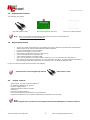
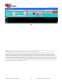
www.bestcircuit.ca
Capacitive touch keypad
Evaluation kit
User manual Rev 2.2
Technical Support 647-388-2976
-1-
email [email protected]
www.bestcircuit.ca
Table of contents
1
Evaluation kit contents
2
Keypad quick startup
3
Keypad features
4
Touch keypad applications
5
Evaluation keypad schematic
6
Software installation
7
Touch parameters setup
8
Error signal
Technical Support 647-388-2976
-2-
email [email protected]
www.bestcircuit.ca
1.0
Evaluation Kit Contents
The evaluation kit contains:
One USB extension cable,
Note:
2.0
One touch keypad (top side view)
One 1.6mm Leaxan dielectric
When the text refers to download a file that means the file can be downloaded from
http://www.bestcircuit.ca/Download.html
Keypad quick startup
•
•
•
•
•
•
•
•
Verify if the 1.6mm Lexan dielectric is well attached on top of the PCB. PCB is provided with a double sided
adhesive tape. No air gaps are allowed between PCB and dielectric.
Connect the USB cable to the touch keypad
Place the touch keypad on a flat surface
Hold in place the USB cable with heavy object (book)
Connect the USB cable to your laptop or PC
The red LED will indicate the keypad is ON
Touch over the dielectric in the area marked in white as key 1, 2 etc and observe the LEDs activity.
Do not touch the keys from the bottom as you may “eliminate” those keys. To restore keypad functionality unplug and plug the USB cable (hard Reset). Or click Reset if you use Windows Application WA.
For how to setup the keypad’s touch parameters see Chapter 6.
Important note: Use the keypad only with the
3.0
-
USB extension cable.
Keypad features
Output signal: four green LEDs and USB serial
On board USB adaptor for PC interface
No power supply needed
Windows Application software interface
USB driver
Power-up valid keys detection
Error signal for bad keys detected during normal operation
Keypad can be attached to your dielectric material (touch parameters must be setup)
Note:
When integrated into a product the touch keypad works without USB adaptor or interface software.
Technical Support 647-388-2976
-3-
email [email protected]
www.bestcircuit.ca
3.1
Touch controller description
Evaluation touch keypad is based on BC8P touch controller. The BC8P is the next-generation version of BC100 and detects the
near proximity or touch of the human finger. Touch controller resolution is about 0.01pF. BC8P series can be use with
dielectrics like glass, plastic, ceramic, stone etc. It can replace up to 8 individual switches or buttons in appliances, vending
machines, elevators etc.
Fig 1
BC8P touch controller can generate an Error signal on pin 11. If during normal operation a key stops working the Error signal
goes High. Soft or hard Reset will return the Error signal to Low state and lower number of valid keys will be reported. This
feature is provided specially for appliance applications. A host controller can interrogate BC8P about keypad integrity.
The BC8P is available in the TQFP-32 package and is specified with two ranges of temperature
-40°C to +85°C or -20°C to 105°C.
Package 32M1-A, 32-pad, 5 x 5 x 1.0 mm Body, Lead Pitch 0.50 mm, Micro Lead Frame also available at your request.
BC8P touch controller features:
•
•
•
•
•
•
•
•
•
•
•
•
•
•
•
•
•
•
•
•
•
•
Up to 8 capacitive or galvanic individual touch keys Fig1
Robust, reliable and proved capacitive technology
Output signal: Binary image for BC8P
Binary image for BC8Pa
Binary image and UART for model BC8PS
Continuous self calibration
Extremely tolerant to environmental changes
Can work in heavy rain if combine with tactile feedback
Dielectric thickness up to 50mm glass or 20mm other materials (key size dependant)
Compatible with grounded metal immediately next to the keys
Key spacing no limitation
Keys can be solid, hollow or transparent
5Vdc operating voltage
Compatible with clear ITO over the LCD-VFD displays
Inexpensive single layer PCB can be used
Brownout
Power-up valid keys evaluation
Error signal bad key detection during normal operation
No calibration before or after keypad production
Temperature range -40°C to +85°C or -20°C to 105°C
32-pin TQFP package, RoHS compliant (other packages available)
Touch parameters setup by Host controller or PC software
Windows Application interface
Integrate your application and touch technology in a single controller
Technical Support 647-388-2976
-4-
email [email protected]
www.bestcircuit.ca
4.
Applications
Appliance controls
Industrial controls
Security key panels
ATMs
5.0
Elevators
Outdoor keypads
Touch screens
Automotive controls
Transparent keypads
Evaluation touch keypad schematic
Evaluation keypad schematic is available in .PDF format from BCI Download webpage.
Circuit is divided two parts:
4keys touch keypad see Fig 2
UART to USB adaptor to allow connection directly to your PC
-
.
Fig 2
Technical Support 647-388-2976
-5-
email [email protected]
www.bestcircuit.ca
6.0
6.1
Software installation
USB driver installation
1. Download and unzip in the specific USB driver in a separate folder
2. Login as Administrator
3. Close all applications
4. Using the USB extension cable connect the Evaluation keypad to your PC
5. The red LED will indicate the keypad is ON
6. When prompted with the message "Found new hardware" follow the installation instructions on the screen and install the
driver.
7. Go to “Control panel" and click on "System" icon to find the serial port number the driver installed.
6.2
Windows Application (WA) installation
WA is a Microsoft .NET Windows application to help the design engineer setup keypad’s parameters and learn about many
features our touch technology has. If your PC does not have already, download for free the Microsoft .NET Framework version
2.0 from http://www.microsoft.com/downloads/details.aspx?FamilyID=0856eacb-4362-4b0d-8eddaab15c5e04f5&displaylang=en
Package will installs the .NET Framework runtime and associated files required to run applications developed to target
the .NET Framework v2.0.
Installation:
1
Download the WA zip package in a separate folder
2
Unzip the package (two files)
3
Launch the WA executable
4
Click on [Serial port] and select the serial port number from 6.1 step 7
If your newly installed serial port is COM5 your screen should look like Fig 3:
Fig3
Technical Support 647-388-2976
-6-
email [email protected]
www.bestcircuit.ca
Click Reset button each time a new the dielectric is placed over the touch keypad or when a key is “eliminated” by touching
directly the PCB sensor without dielectric.
Touching the keypad without dielectric creates a large amount of touch signal which will indicate a bad key and an Alarm
signal will be activated. To restore keypad’s functionality Reset the keypad.
7.0
Keypad parameters setup
Touch Parameters control the whole keypad from one place. Different parasitic capacitance caused by key size, parts
tolerances, humidity and temperature creates different characteristics keys. To avoid setting four parameters for each key
more like a calibration process we use an adaptive parameter algorithm which “adapts” the main parameter to the individual
parameter key. This way all keys “feel” even. We called the resulted parameters as “Dynamic Parameters” as they change
continuously to maintain the same “keypad feel” from the setup.
Parameter values can be adjusted between 1 and 63.
Evaluation board comes optimized for 1.6 mm Lexan or the equivalent of a 4 mm glass pane.
For production purpose parameters can be loaded with customer’s specific values at no cost. Touch parameters can be
adjusted at any time by the WA or the host controller.
Read parameters with [Read parameters] button
Write parameter with [Write parameters] button.
Click on a key from [Selected key values] to displays its Base, Absolute and Delta values.
Delta represents difference between Absolute and Base value. In other words the difference between Touch and no-Touch
signal
When key is not activated (no-Touch) Delta is almost zero.
Large size keys, thin dielectrics or high capacitive coefficient constants will create large Delta values. When a key is activated
a 0.5” x 0.5” sensor should generate Delta values between 20 and 100 proportional with the finger pressure and size. Delta
values higher than 100 indicates large Base value, meaning a lower base resistor is recommended. See Design
Recommendations white paper.
Threshold parameter sets the safety gap between the Touch and no-Touch condition. In other words sets the keypad’s
sensitivity
Hysteresis parameter helps to maintain the Touch condition even when the operator’s finger is unstable over the key. It is
active only on the release. For a keypad stable functionality Hysteresis value must be lower few counts than Threshold
parameter.
Noise Filter parameter is responsible to filter the touch signal. To visualize the a key touch signal start the oscilloscope and
set this parameter accordingly to your needs. Recommended value is 20 and over. Lower values are acceptable in low noise
environments. Higher values will create greater protection but will decrease in keypad time response. Very low values create
an create an unstable keypad.
Stuck key will set the maximum time a key can be hold active. Parameter value 63 will let an activated key hold for 20
seconds. After that the key will reset.
8.0
Error signal
At Power-up initialization BCP8x detects the number of good working keys and after that controller enters normal operation.
During normal operation controller scans each key to check on keys’ the health. If a bad key is detected a continuous Error
signal is activated. Soft or hard Reset will cancel the Error signal
After a hard or soft reset BC8S will report a lower number of detected keys. Host controller can interrogate touch controller
about keys integrity at any time.
Fig 4 shows an AW snapshot with the Error signal activated. Key4 is bad in this case. Notice the text in blue: detected keys 4,
valid keys 3. A buzzer or LED can be attached to pin 11.
Technical Support 647-388-2976
-7-
email [email protected]
www.bestcircuit.ca
Fig 4
Disclaimer: The information in this document is provided in connection with Best Circuit Inc products. No license, express or implied, by estoppel or otherwise, to
an intellectual property right is granted by this document or in connection with the sale of BCI products.
WARRANTY RELATING TO ITS PRODUCTS INCLUDING, BUT NOT LIMITED TO, THE IMPLIED WARRANTY OF MERCHANTABILITY,
FITNESS FOR A PARTICULAR PURPOSE, OR NON-INFRINGEMENT. IN NO EVENT SHALL BCI BE LIABLE FOR ANY DIRECT, INDIRECT,
CONSEQUENTIAL, PUNITIVE, SPECIAL OR INCIDENTAL DAMAGES (INCLUDING, WITHOUT LIMITATION, DAMAGES FOR LOSS OF
PROFITS, BUSINESS INTERRUPTION, OR LOSS OF INFORMATION) ARISING OUT OF THE USE OR INABILITY TO USE THIS DOCUMENT,
EVEN IF BCI HAS BEEN ADVISED OF THE POSSIBILITY OF SUCH DAMAGES. BCI makes no representations or warranties with respect to the accuracy
or completeness of the contents of this document and reserves the right to make changes to specifications and product descriptions at any time without notice. BCI
does not make any commitment to update the information contained herein. Unless specifically provided otherwise, BCI products are not suitable for, and shall not
be used in, automotive applications. BCI products are not intended, authorized, or warranted for use as components in applications intended to support or sustain
life. Other terms and product names may be trademarks of others.
Technical Support 647-388-2976
-8-
email [email protected]