1
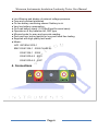
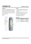
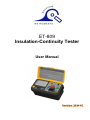
ET-809
Insulation-Continuity Tester
User Manual
Wavecom Instruments Insulation-Continuity Tester User Manual
Index
Safety Precautions.......................................................
1-2
Safety Notes................................................................
3
Features.......................................................................
3-4
Connections.................................................................
4
Specifications...............................................................
5
Why Test is Necessary.................................................
6
Instrument Layout........................................................
7
Simplified Instructions..................................................
8-9
Preparation for Measurement......................................
9
Functions.....................................................................
10-16
Battery & Fuse Replacement.......................................
17
Calibration & Servicing................................................
17
Cleaning & Storage.....................................................
17
Page 2
Wavecom Instruments Insulation-Continuity Tester User Manual
1. Safety Precautions
Electricity can cause severe injuries even with low voltages or currents.
Therefore it is extremely important that you read the following
information before using your analogue tester.
1.1 This Instrument must only be used and operated by a
competent trained person and in strict accordance with the instructions.
Wavecom will not accept liability for any damage or injury caused by
misuse or non compliance with instructions and safety procedures.
1.2 This instrument must not be used on live circuits. Ensure
all circuits are de-energised before testing. See paragraph 1.8 for
details of built-in warning features should your analog insulation tester
be connected to a live system.
1.3 Never open your analogue insulation tester except for
battery replacement. (see battery replacement section)
1.4 Always inspect you analog insulation tester and test
leads before use for any sign of abnormality or damage. If any
abnormal conditions exist (broken test leads, cracked case, display
faulty etc...) do not attempt to take any measurement or use the tester.
Return your analogue insulation tester to your nearest distributor for
service.
1.5 Never replace the protective fuse with any other than the specified or
equivalent
1.6 Your analogue insulation tester has been designed with
your safety in mind. However, no design can completely protect
against incorrect use. Electrical circuits can be dangerous and / or
lethal when a lack of caution or poor safety practice is used.
Page 3
Wavecom Instruments Insulation-Continuity Tester User Manual
Use with caution in the presence of voltage above 24V as
these pose a shock hazard.
1.7 Pay attention to cautions and warnings which will inform
you of potentially dangerous procedures.
1.8 Your analogue insulation tester has a live circuit warning
beeper. If it is connected to an AC live circuit, a beep of twice the
frequency of the voltage present will be heard.
DO NOT proceed to test and immediately disconnect the
instrument from the circuit. In addition, the warning light will
illuminate if the voltage is above 100Vdc or 70Vac.
When AC voltage is present, before testing, it's value is
displayed on the AC scale.
Page 4
Wavecom Instruments Insulation-Continuity Tester User Manual
2. Safety Notes
Rated environmental condition
(1) Indoor use.
(2) Installation Category Ⅲ.
(3) Pollution Degree 2.
(4) Altitude up to 2000M.
(5) Relative humidity 80% Max.
(6)
Ambient temperature 0°C~40°C.
Meter is protected throughout by double insulation or reinforced
insulation.
Warning ! risk of electric shock.
Caution ! refer to this manual before using the meter.
3. Features
● High quality taut band movement.
● Three insulation test voltages:
1250Vdc
100MΩ
2500Vdc
200MΩ
31000Vdc
400MΩ
● Two continuity test on "Low Ohms":
1500Ω
23Ω
● Small and Lightweight.
● AC voltmeter with linear scale up to 500Vac.
● 205mA continuity short circuit current.
● 1mA test current on insulation test at nominal voltage.
● Automatic discharge of capacitance and inductive circuit off
charge stored in the circuit under test..
Page 5
Wavecom Instruments Insulation-Continuity Tester User Manual
● Live Warning and display of external voltage presence.
● Fuse and overload protected.
● On line battery monitoring shows if battery is ok.
● Very low battery consumption.
● On-Load battery check (+/-205mA load for worst case).
● Operates on 8 dry batteries AA, R6P type.
● Mirrored scale for easy and accurate reading.
● Push and turn locking switch for long and hand free testing.
● Supplied with high quality test leads.
● Meets:
LVD IEC/EN 61010-1
EMC EN 61326-1:2006 CLASS B
EN 61326-1:2006
EN 61000-4-2:2001
EN 61000-4-3:2007
4. Connections
Page 6
Wavecom Instruments Insulation-Continuity Tester User Manual
5. Specifications
INSULATION
● Test Voltage
250Vdc
500Vdc
1000Vdc
+10%-0%
+10%-0%
+10%-0%
● Mirror scale
100MΩ
200MΩ
400MΩ
● Mid-Scale
1MΩ
2MΩ
4MΩ
● Scale Multiplier
x1/2
x1
x2
● Accuracy
±5%
● Output short-circuit current
±1.3mA
● Regulated output voltage (up to 1mA current)
263.5V
525V
1052V
CONTINUITY
● Low Ω:3Ω / 500Ω
● Test leads / fuse zero Ω adjustment by knob.
● Output short-circuit current:205mA
● Accuracy:±1.5% of scale length
AC VOLTAGE
● Range:0 - 500Vac
● Accuracy:±3% of scale length
GENERAL
● Voltage Warning:Warning light circuit live illuminate from 90Vdc/70Vac. Buzzer
beep from 24Vac/dc.
● Battery Check:Battery Check indicate good batteries from 8Vdc to 13Vdc during
a load test of 205mA.
● Battery OK:Battery OK Led illuminate from 8Vdc and is operative while testing.
● Power Source:1.5V(AA) x 8
● Dimension:175(L) x 85(W) x 75(H)mm
Weight:Approx. 650g (battery included)
● Accessories include:
Test leads
Fuse (0.5A/500V 5x20mm)
Carrying case
Instruction manual
Batteries.
Page 7
Wavecom Instruments Insulation-Continuity Tester User Manual
6. Why Test is Necessary?
INSULATION
Every electrical apparatus and installation need to be safe for the user and
for the equipment itself.
Electrical conductors of electricity need to be insulated from each other, so
that they do not create electrical hazard or unnecessary consumption.
Badly insulated circuits can create leakage current which can be dangerous
and trip your GFCI, RCCB or ELCB.
Each country regulates these levels at which the insulation is acceptable.
Generally, insulation resistance measurements are done between each
conductor and the earth, and between each conductors.
CONTINUITY
Checking the continuity of wires, complete circuits, connections, closure of
contacts, circuit breakers, fuses, bounding resistance of connections, etc...
are all very important.
Page 8
Wavecom Instruments Insulation-Continuity Tester User Manual
7. Instrument Layout
1.Test Button Switch
2.Function Selector
3.Battery OK indicator
4.Mirror Scale
5.Live Circuit Warning Light
6.Test Leads and Fuse Zeroing Knob
Page 9
Wavecom Instruments Insulation-Continuity Tester User Manual
8. Simplified Instructions
INSTRUCTIONS ANALOGUE INSULATION-CONTINUITY TESTER
WARNING
This instrument must only be used by a competent trained
individual. Consult the full operating instructions. Never
press the test button before connecting test leads to circuit
to test.
INITIAL CHECKS
1. Switch to "Batt. Check" and depress the test button. If the pointer does
not move to "BAT.OK", the battery needs to be replaced before
proceeding.
2. Connect test leads to instrument, switch to 3Ω. Press and turn the test
button (continuous mode), short the test leads. The pointer should swing
from infinite towards zero. If not, the test leads or fuse (0.5A fast acting
ceramic) maybe faulty.
INSULATION TESTS MΩ RANGES
1. Select the desired insulation test voltage range, 250V, 500V, or 1000V.
2. Connect the leads to the instrument and circuit under test.
3. Check the circuit is not LIVE.
4. Press the test button. Read the red MΩ scale directly for 500V, multiply
by 0.5 (or divide by 2) for 250V and multiply by 2 for 1000V.
Page 10
Wavecom Instruments Insulation-Continuity Tester User Manual
CONTINUITY TESTS - Ω RANGES
1. Select the desired ohm range, 3Ω or 500Ω.
2. Short the test leads, press test button and adjust the ohms zero ADJ to
zero the pointer on the 0Ω (green scale).
3. Check the circuit is not LIVE.
4. Connect the test leads to the circuit under test. Press the test button.
Read the selected range directly.
GENERAL
● For AC voltmeter, do not press the test button, this is the default mode of
the instrument.
● AC voltmeter operates without batteries.
● Insulation or continuity mode: for continuous operation, press and turn the
test button.
SAFETY PRECAUTION
● The circuit must not be LIVE, conduct initial checks first. If at any time ,
the "LIVE" circuit light is illuminated, or the warning buzzer sounds - DO
NOT PROCEED, the circuit is live.
● Using the instrument in Insulation Mode may leave the
Circuits charged up if test leads are removed too quickly.
Avoid this by releasing the test button while the test leads are still
connected to the circuit for a few seconds.
9. Preparation for Measurement
Before testing Always check the following.
At Power "ON", check that Bat. OK led illuminate and check that there is no
visual damage to the Instrument or test leads.
Check the test Leads continuity:
1. Connect the leads to the Instrument.
2. Zero the test leads while on the 3 ohm range.
3. This will indicate that the continuity of the test leads is Ok.
4. Verify that the test leads insulation is in good condition.
Page 11
Wavecom Instruments Insulation-Continuity Tester User Manual
10. Functions
10.1 Battery Check
Turn the function selector to Batt. Check. This function has a load
which draw about 205mA when test is performed, and therefore it is
doing a worst case battery test.
Then, press the test button, the pointer should be in the
BAT.OK area. During the test, the bat. OK Led (on line battery check)
must illuminate if the pointer is in the BAT.OK area.
Page 12
Wavecom Instruments Insulation-Continuity Tester User Manual
10.2 DC Warning
The DC warning buzzer will beep continuously when DC voltage is
higher than 30Vdc on the test probes and the test button is not
pressed. The neon light "circuit live" will illuminate when the voltage on
the test probes is higher than 90Vdc and the test button is not
pressed.
10.3 AC Warning
The AC warning buzzer will beep continuously when AC voltage is
higher than 20Vac on the test probes and the test button is not
pressed. The neon light "circuit live" will illuminate when the voltage on
the test probes is higher than 65Vdc and the test button is not
pressed.
10.4 AC Measurement
The AC measurement is automatic on this instrument. As soon as AC
voltage is present on the test leads, the instrument will display the AC
voltage from 20 to 500Vac on the linear scale.
Page 13
Wavecom Instruments Insulation-Continuity Tester User Manual
10.5
Low Ohms Measurement 0 - 500Ω
Always check for voltage before testing and measuring on
a circuit. This instrument is intended for measuring Low Ω
and Insulation resistance on un- energized circuits only.
Use the procedure explained at points 10.2, 10.3, 10.4.
The first procedure to follow, is to zero the test leads II and II
the fuse resistance. The instrument is equipped with a Zero Ω Knob.
First, short circuit the test leads by connecting them together, then, press
the test button and adjust the zero Ω knob until the pointer is precisely on
the "0" of the 500Ω scale.Use the mirror scale to be precise with the pointer.
Page 14
Wavecom Instruments Insulation-Continuity Tester User Manual
Connect the test leads to the
circuit to be measured.
For short test, press button and
keep pressed. For long test or
hand free measurements, press
and turn the test button.
10.6 Low Ohms Measurement 0 – 3Ω
Always check for voltage before testing and measuring on
a circuit. This instrument is intended for measuring Low Ω
and Insulation resistance on un-energized circuits only.
Use the procedure explained at points 10.2, 10.3, 10.4.
The first procedure to follow, is to zero the test leads and
the fuse resistance.The instrument is equipped with a Zero Ω Knob.
First, short circuit the test leads by connecting them
together, then, press the test button and adjust the zero Ω
knob until the pointer is precisely on the "0" of the 3Ω scale.
Use the mirror scale to be precise with the pointer.
Page 15
Wavecom Instruments Insulation-Continuity Tester User Manual
Connect the test leads to the circuit to be measured.
For short test, press button
and keep pressed.
For long test or hand free
Measurements, press and
turn the test button.
10.7 Insulation Resistance Measurement @ 250Vdc
Always check for voltage before testing and measuring on a circuit. This
instrument is intended for measuring Low Ω and Insulation resistance on
un-energized circuits only.
Use the procedure explained at points 10.2, 10.3, 10.4.
Check the test leads and fuse resistance by zeroing the test leads and fuse
as per the 7.6 procedure. Connect the test leads to the circuit to be
measured and wait for a few seconds. The instrument will automatically
discharge any remaining energy which could be present on the circuit, and
will check for voltage at the same time.
Page 16
Wavecom Instruments Insulation-Continuity Tester User Manual
Once you are sure that the circuit to be tested is not
energized, then press the button for a short test duration or press and turn
the button for a long test.Once you end the test, allow a few seconds for the
Instrument to automatically discharge the circuit.
10.8 Insulation Resistance Measurement @ 500Vdc
Always check for voltage before testing and measuring on a circuit. This
instrument is intended for measuring Low Ω and Insulation resistance on
un-energized circuits only.
Use the procedure explained at points 10.2, 10.3, 10.4.
Check the test leads and fuse resistance by zeroing the test leads and fuse
as per the 7.6 procedure.
Connect the test leads to the circuit to be measured and wait for a few
seconds. The instrument will automatically discharge any remaining energy
which could be present on the circuit, and will check for voltage at the same
time.
Page 17
Wavecom Instruments Insulation-Continuity Tester User Manual
10.9 Insulation Resistance Measurement @ 1000Vdc
Always check for voltage before testing and measuring on a circuit. This
instrument is intended for measuring Low Ω and Insulation resistance on
un-energized circuits only.
Use the procedure explained at points 10.2, 10.3, 10.4.
Check the test leads and fuse resistance by zeroing the
test leads and fuse as per the 7.6 procedure. Connect the test leads to the
circuit to be measured and wait for a few seconds. The instrument will
automatically discharge any remaining energy which could be present on
the circuit, and will check for voltage at the same time.
Once you are sure that the circuit to be tested is not
energized, then press the button for a short test duration
or press and turn the button for a long test.
Once you end the test, allow a few seconds for the instrument to
automatically discharge the circuit.
Page 18
Wavecom Instruments Insulation-Continuity Tester User Manual
11. Battery & Fuse Replacement
11.1 Battery Replacement
Your analogue insulation tester's battery compartment is situated
under the tester. The BAT.OK will not illuminate when batteries need to
be replaced. Disconnect the test leads from the Instrument, remove
the battery cover and the batteries.
Replace with eight 1.5V R6 or L6 batteries, taking care to observe the
correct polarity.
Replace batteries and the battery cover.
11.2 Fuse replacement
The fuse is located next to the batteries. To replace fuse, proceed as
per battery replacement to open the battery cover, then remove and
replace the fuse located under the battery holder. Only replace with
same specification fuse.(0.5A/500V)
12. Calibration & Servicing
Contact your nearest distributor about calibration certificate and servicing.
Before returning the instrument, ensure that:
● the leads have been checked for continuity and signs of damage.
● the batteries are in good condition.
Page 19
Wavecom Instruments Insulation-Continuity Tester User Manual
13. Cleaning & Storage
Periodically, wipe the case with a damp cloth and detergent
; do not use abrasives or solvents.
If meter is not to be used for periods longer than 60 days,
Remove the batteries and store them separately.
CAT Ⅳ - Is for measurements performed at the source of the low-voltage
installation.
CAT Ⅲ - Is for measurements performed in the building Installation.
CAT Ⅱ - Is for measurements performed on circuits directly connected to the
low-voltage installation.
CAT Ⅰ - Is for measurements performed on circuits not directly connected to
mains.
Due to our policy of constant improvement and development, we reserve the right to change specifications
without notice.
Page 20