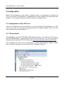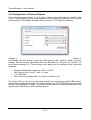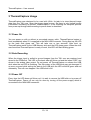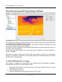
1
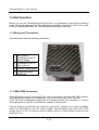
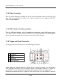
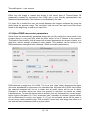
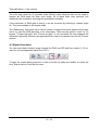
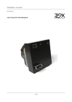
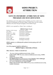
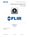
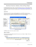
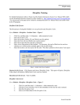
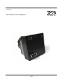
(rev2 May 2014)
User manual for ThermalCapture
1 / 14
ThermalCapture – User manual
Table of Contents
1 Initial Operation...................................................................................................................3
1.1 Wiring and Connectors................................................................................................3
1.1.1 Mini-USB Connector.............................................................................................3
1.1.2 Video Connector...................................................................................................4
1.1.3 USB Interface for Memory Stick...........................................................................4
1.1.4 Trigger and Serial Connector...............................................................................4
2 Configuration.......................................................................................................................6
2.1 Configuration of the TAU Core.....................................................................................6
2.1.1 Driver Install..........................................................................................................6
2.1.2. Flir Software Installation......................................................................................7
2.1.3 TAU Configuration................................................................................................7
2.2 Configuration of ThermalCapture................................................................................9
3 ThermalCapture Usage.....................................................................................................10
3.1 Power On...................................................................................................................10
3.2 Data Recording..........................................................................................................10
3.3 Power Off...................................................................................................................10
4 Post Processing with ThermoViewer Software.................................................................11
4.1 Open RAW data files or images.................................................................................11
4.2 Adjust RAW conversion parameters..........................................................................12
4.3 Export functions.........................................................................................................13
4.4 NMEA Parser.............................................................................................................14
2 / 14
ThermalCapture – User manual
1 Initial Operation
Before you can use ThermalCapture the first time, it is necessary to proceed the following
steps. This guide assumes that ThermalCapture is already mounted to a TAU core. If this
is not the case please follow the ThermalCapture Mounting Guide first.
1.1 Wiring and Connectors
ThermalCapture has the following connectors:
1
Mini-USB for
configuration and 5V
Power Supply
2
Composite NTSC or
PAL video out
3
USB for memory stick
4
Trigger and serial
connector
1.1.1 Mini-USB Connector
ThermalCapture and the connected TAU core are powered from the Mini-USB interface.
This interface also allows the configuration of the TAU core via the FLIR TAU GUI.
To do TAU core configuration disconnect any memory device from connector 3, connect
ThermalCapture to your PC and follow the chapter 2 of this guide.
Thermal Capture is intended to be used with small UAVs. Therefore you need an adapter
cable from Mini-USB to your 5V power supply. ThermalCapture can work with a DC
voltage from 5 to 6V. The source must be able to deliver at least 600mA continuous and
peeks up to 1A.
3 / 14
ThermalCapture – User manual
1.1.2 Video Connector
This is a MCX connector, providing the NTSC or PAL composite video out from the TAU
core. The video standard and other video related settings can be configured with FLIR
TAU GUI, see chapter 2.
1.1.3 USB Interface for Memory Stick
This is a USB host interface, which is intended to be used with a small USB memory stick.
It is able to power common memory sticks, but not USB hard-drives. ThermalCapture
stores the captured images on the memory connected to this interface.
1.1.4 Trigger and Serial Connector
The trigger and serial connector has the following pin definition:
1
Trigger IN
2
GND
3
Serial IN
4
NC Reserved
Image capture is triggered when the Trigger IN pin is pulled to ground. It is connected to
3.3V internally via resistor. You can apply a switch or a transistor between 1 (Trigger IN)
and 2 (GND). It is also possible to connect a digital signal (0-5V) to the trigger input.
Images are captured as long as Trigger IN is at ground level. It is not possible to connect
4 / 14
ThermalCapture – User manual
the trigger input permanently to GND, because in this case there would be no way to
switch ThermalCapture off or release the memory stick, without potentially damaging its
file-system.
Serial IN is a UART interface. It supports inverted and not inverted signals (0-5V). The
data received at this pin is continuously stored in an internal buffer. This buffer is added to
any stored image. So it is possible to connect a GPS receiver or an IMU to
ThermalCapture. Since the data is only stored but not processed at ThermalCapture, any
UART based protocol can be used as long the sensor begins with data output on its own.
Interface settings (baud rate etc.) can be done with the serial configuration tool (see
chapter 2).
5 / 14
ThermalCapture – User manual
2 Configuration
Before ThermalCapture can be used in a specific setup, it is necessary to configure the
TAU core correctly. Configuration of ThermalCapture is only needed if the serial input (see
chapter 1.1.4) is used to connect to a GPS receiver or a similar device.
2.1 Configuration of the TAU Core
TAU core configuration is only necessary if you have mounted ThermalCapture to a TAU
core on your own, or if you want to change some core related settings. If this is not the
case, please proceed with chapter 2.2.
2.1.1 Driver Install
ThermalCapture uses the FTDI232RL USB serial converter IC to connect the TAU core to
the Mini-USB interface. To get access to the TAU core with your PC, you may need to
download and install the FTDI VCP driver from http://www.ftdichip.com/Drivers/VCP.htm .
After installation the TAU core is connected to a virtual serial interface (COMX). Please
open the device manager and look which COM – interface it has got.
6 / 14
ThermalCapture – User manual
2.1.2. Flir Software Installation
The configuration of the Tau core is done by software from FLIR.
You need the FLIR Camera Controller GUI for Tau and Quark:
http://www.flir.com/cvs/cores/view/?id=51880
and the FLIR GUI User Guide:
http://www.flir.com/uploadedFiles/CVS_Americas/Cores_and_Components_NEW/Resourc
es/GUI_UsersGuide_r100.pdf
Connect the Mini-USB interface of ThermalCapture to your PC and follow Chapter 4 of the
FLIR GUI User Guide to connect to the camera.
2.1.3 TAU Configuration
ThermalCapture gets the images from the digital output of the TAU core. This output is
switched off by default. If the output is not enabled, ThermalCapture cannot record images.
The digital output must be enabled with the Flir "Camera Controller GUI".
After the FLIR GUI has connected to the TAU core, go to the Digital Video Tab and select
CMOS for XP Bus Output and 14-bit filtered output.
If your TAU core has the “advanced radiometry option”, TLinear should be enabled to have
per pixel temperature measurement in ThermoViewer.
7 / 14
ThermalCapture – User manual
These settings must be saved permanently. To achieve this, go to the Setup tab and click
to Save Settings.
Without this, the settings will be lost with the next power cycle and recording cannot work.
Now the TAU core is ready to be used with ThermalCapture.
8 / 14
ThermalCapture – User manual
2.2 Configuration of ThermalCapture
If the serial input (see chapter 1.1.4) is used, it needs to be configured for a specific data
source. ThermalCapture is delivered together with a configuration software to set up this
serial interface. This chapter describes how to use the TC-Configurator software.
Settings for the serial interface are communicated to ThermalCapture by generating a
configuration file and saving it onto the USB memory stick, which is used for picture
storage. This file contains information about the Baudrate (1), Parity Bit- (2), Stop Bit- (3)
and Inversion-settings (4). These settings must agree with the settings of the connected
hardware.
•
•
•
•
Supported Baudrates range from 1200 to 115200
Parity can be set to “none”, “odd”, or “even”
1 or 2 Stop bits
The check box (4) determines, if inversion is active or not
The button “Write to file” opens a file dialog in which the root directory of the USB memory
stick should be selected as target. The supposed filename “TCCONFIG.BIN” must be used
to allow ThermalCapture to read it. The file can also be saved to a different destination and
copied to the USB memory stick manually later on.
9 / 14
ThermalCapture – User manual
3 ThermalCapture Usage
ThermalCapture was designed to be used with UAVs. Its task is to store thermal image
data from the TAU core, when the trigger signal occurs. So there is only limited human
intervention necessary to operate ThermalCapture. In the following the complete process
from power up through data recording to power down is described.
3.1 Power On
You can power on with or without a connected memory stick. ThermalCapture begins to
boot immediately when 5V is supplied to the MINI-USB connector. During boot up the LED
on the back side glows red. This will take one or two seconds. After boot up
ThermalCapture waits for the USB Memory stick and the LED glows green. When the stick
was found and ThermalCapture is ready to work, this LED will start blinking green.
3.2 Data Recording
When the trigger input is pulled to ground images from the TAU core are captured and
stored to the USB stick. The LED on the back side will flicker red and the letters “REC” are
shown in the analog video output. Do not power off ThermalCapture or release the USB
stick when the red LED is flickering. The file-system of the USB stick may get damaged. If
an error occurred while writing the data to the USB stick the LED will blink green and red
alternately. This will even happen if the USB stick is full.
3.3 Power Off
Every time the LED does not flicker red, it is safe to remove the USB stick or to power off
ThermalCapture. Power off can only be done by turning off the power supply which is
connected to the MINI-USB connector.
10 / 14
ThermalCapture – User manual
4 Post Processing with ThermoViewer Software
The image above shows a standard ThermoViewer window, while working with RAW data.
The user interface is divided into three parts:
The left side of the window is the file selection area where the folder containing the image
(1) and the image to show (2) are selected.
The center area (3) shows the converted RAW data either as a black and white image, or
as a false color interpretation.
On the right side (4) information from serial data and the position of image acquisition is
shown, if available.
The toolbar (5) gives access to file input and output options and also to configuration
dialogs. If a video file is loaded the video control options (6) will appear below the preview
window of the converted data.
4.1 Open RAW data files or images
This software is capable of showing RAW data collected with ThermalCapture hardware.
Opening files can be done in three different ways:
1. Select the folder directly in the directory tree (1) and after that select the file to open
by clicking on it once (2)
2. Use the toolbar buttons (5)
3. Use the corresponding menu items within the “File” menu
11 / 14
ThermalCapture – User manual
Either way the image is loaded and shown in the center area of ThermoViewer. All
parameters needed for conversion from RAW into a user friendly representation are
determined automatically, if this feature is not disabled by the user.
If a video file is loaded the user can switch between the images contained by using the
slider below the preview image. The “set begin” and “set end” are used to set the current
frame as the beginning, or end for an export run.
4.2 Adjust RAW conversion parameters
Some times the automatically generated images do not fully satisfy the users needs. Let's
imagine there is a very hot spot within the data, which is not of interest at the moment.
This leads to the situation, that all areas with a lower temperature are shown in black, or a
dark blue, without enough contrast to catch details. This problem can be solved in the
RAW parameters settings window (Settings / RAW conversion parameters):
RAW data has a range from 0 to 16384. The “Low” and “High” sliders determine the upper
and lower boundaries for conversion into viewable data. All pixels with a RAW value below
the selected threshold will be set to black and all pixels above will be set to white.
Changes of the slider values are taken into account in real-time, so results are visible
instantaneously. To reset the values back to default, click the “Automatic for current image”
button right to the faders (2). If the “Automatic gain” checkbox is checked, optimal values
will be determined for every new image. If it is not, the selected values will be used to
convert every newly loaded image. This is helpful if more than one image was taken in a
row and the same parameters lead to a good result.
12 / 14
ThermalCapture – User manual
The color drop down list (3) provides three different color schemes that can be used to
transfer the RAW data into false color image. All of these three color schemes can
additionally be inverted by checking the appropriate checkbox.
If the orientation of RAW data is wrong, it can be corrected by selecting a rotation angle
(4). They are available in 90 degree steps.
The “Radiometry” drop down list is used to chose if a legend should be added to the image
and if so, how the RAW data has to be interpreted. There are the options “none” for no
legend, “TLinear high gain” and “TLinear low gain”. If the connected Tau core supports the
advanced radiometry features, the appropriate item has to be chosen from the two TLinear
options.
4.3 Export functions
You can export data to binary image formats like PNG and JPG and from version 1.3.2 on,
also into comma separated value files (CSV).
To open the export dialog press the 4 th item from the left within the toolbar, or select the
item “Export frames” from the file menu.
13 / 14
ThermalCapture – User manual
In the “Frame export” dialog the user can set all necessary option for the export of single
or multiple frames. The first step is to select frames, which should be exported. The values
in the input fields (1) are taken from the main window input fields, but can be adjusted here
if needed.
The target format can be selected by the drop down menu (2). Available formats are PNG,
JPG and CSV. PNG images are stored lossless, which means that no compression errors
appear in the final image. JPG uses non-lossless compression, but delivers far smaller
data sizes. CSV writes the temperature values into a comma separated value file, which
can be used in any application which can open these files, like Microsoft Excel, or Matlab.
The target directory into which the output files will be written can be entered manually into
the text field (3), or can comfortable be selected by opening a file browsing window using
the button.
The target name consists of three parts. The first part can be entered by the user into the
textfield (4). ThermoViewer will automatically add a continuous number to this name and
also the extension selected in (2).
4.4 NMEA Parser
If you connect a GPS receiver to the serial interface of ThermalCapture and the device is
set up to send NMEA data, then you are able to activate the “Parse NMEA Data” option in
Settings menu. Extracted data from the GPRMC messages is then shown on the right side
of ThermalViewer main window.
14 / 14