
1
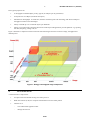
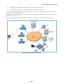
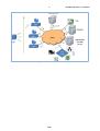
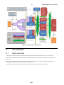
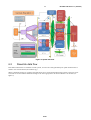
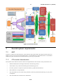
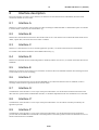
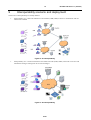
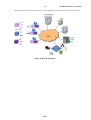
ETSI GS LTN 002 V1.1.1 (2014-09)
GROUP SPECIFICATION
Low Throughput Networks (LTN);
Functional Architecture
Disclaimer
This document has been produced and approved by the Low Throughput Networks (LTN) ETSI Industry Specification Group
(ISG) and represents the views of those members who participated in this ISG.
It does not necessarily represent the views of the entire ETSI membership.
2
ETSI GS LTN 002 V1.1.1 (2014-09)
Reference
DGS/LTN-002
Keywords
IoT, LTN, M2M
ETSI
650 Route des Lucioles
F-06921 Sophia Antipolis Cedex - FRANCE
Tel.: +33 4 92 94 42 00 Fax: +33 4 93 65 47 16
Siret N° 348 623 562 00017 - NAF 742 C
Association à but non lucratif enregistrée à la
Sous-Préfecture de Grasse (06) N° 7803/88
Important notice
The present document can be downloaded from:
http://www.etsi.org
The present document may be made available in electronic versions and/or in print. The content of any electronic and/or
print versions of the present document shall not be modified without the prior written authorization of ETSI. In case of any
existing or perceived difference in contents between such versions and/or in print, the only prevailing document is the
print of the Portable Document Format (PDF) version kept on a specific network drive within ETSI Secretariat.
Users of the present document should be aware that the document may be subject to revision or change of status.
Information on the current status of this and other ETSI documents is available at
http://portal.etsi.org/tb/status/status.asp
If you find errors in the present document, please send your comment to one of the following services:
http://portal.etsi.org/chaircor/ETSI_support.asp
Copyright Notification
No part may be reproduced or utilized in any form or by any means, electronic or mechanical, including photocopying
and microfilm except as authorized by written permission of ETSI.
The content of the PDF version shall not be modified without the written authorization of ETSI.
The copyright and the foregoing restriction extend to reproduction in all media.
© European Telecommunications Standards Institute 2014.
All rights reserved.
TM
TM
TM
DECT , PLUGTESTS , UMTS and the ETSI logo are Trade Marks of ETSI registered for the benefit of its Members.
TM
3GPP and LTE™ are Trade Marks of ETSI registered for the benefit of its Members and
of the 3GPP Organizational Partners.
GSM® and the GSM logo are Trade Marks registered and owned by the GSM Association.
ETSI
3
ETSI GS LTN 002 V1.1.1 (2014-09)
Contents
Intellectual Property Rights ................................................................................................................................4
Foreword.............................................................................................................................................................4
Modal verbs terminology....................................................................................................................................4
Introduction ........................................................................................................................................................4
1
Scope ........................................................................................................................................................5
2
References ................................................................................................................................................5
2.1
2.2
3
3.1
3.2
Normative references ......................................................................................................................................... 5
Informative references ........................................................................................................................................ 5
Definitions and abbreviations ...................................................................................................................5
Definitions .......................................................................................................................................................... 5
Abbreviations ..................................................................................................................................................... 6
4
Low Throughput Networks ......................................................................................................................6
5
Architecture ..............................................................................................................................................7
6
LTN data flow ........................................................................................................................................10
6.1
6.2
7
7.1
7.1.1
7.2
7.3
7.3.1
7.3.2
7.3.3
7.3.4
7.3.4.1
7.3.4.2
7.4
8
8.1
8.2
8.3
8.4
8.5
8.6
8.7
8.8
8.9
9
Uplink data flow ............................................................................................................................................... 10
Downlink data flow .......................................................................................................................................... 11
Overall system requirements ..................................................................................................................12
LEP ................................................................................................................................................................... 12
LTN module characteristics ........................................................................................................................ 12
LTN Radio Networks ....................................................................................................................................... 13
LAP .................................................................................................................................................................. 13
LTN radio front end .................................................................................................................................... 13
LTN messages management ....................................................................................................................... 13
LTN Network Management agent .............................................................................................................. 13
LTN Server ................................................................................................................................................. 14
LTN Message processing ...................................................................................................................... 14
Networks management .......................................................................................................................... 14
CRA (for UNB implementation only) .............................................................................................................. 14
Interface description ...............................................................................................................................15
Interface A ........................................................................................................................................................ 15
Interface B ........................................................................................................................................................ 15
Interface C ........................................................................................................................................................ 15
Interface D ........................................................................................................................................................ 15
Interface E ........................................................................................................................................................ 15
Interface F ........................................................................................................................................................ 15
Interface A' ....................................................................................................................................................... 15
Interface C' ....................................................................................................................................................... 15
Interface F' ........................................................................................................................................................ 15
Interoperability scenario and deployment ..............................................................................................16
Annex A (informative):
Authors & contributors .................................................................................18
Annex B (informative):
Bibliography ...................................................................................................19
History ..............................................................................................................................................................20
ETSI
4
ETSI GS LTN 002 V1.1.1 (2014-09)
Intellectual Property Rights
IPRs essential or potentially essential to the present document may have been declared to ETSI. The information
pertaining to these essential IPRs, if any, is publicly available for ETSI members and non-members, and can be found
in ETSI SR 000 314: "Intellectual Property Rights (IPRs); Essential, or potentially Essential, IPRs notified to ETSI in
respect of ETSI standards", which is available from the ETSI Secretariat. Latest updates are available on the ETSI Web
server (http://ipr.etsi.org).
Pursuant to the ETSI IPR Policy, no investigation, including IPR searches, has been carried out by ETSI. No guarantee
can be given as to the existence of other IPRs not referenced in ETSI SR 000 314 (or the updates on the ETSI Web
server) which are, or may be, or may become, essential to the present document.
Foreword
This Group Specification (GS) has been produced by ETSI Industry Specification Group (ISG) Low Throughput
Networks (LTN).
Modal verbs terminology
In the present document "shall", "shall not", "should", "should not", "may", "may not", "need", "need not", "will",
"will not", "can" and "cannot" are to be interpreted as described in clause 3.2 of the ETSI Drafting Rules (Verbal forms
for the expression of provisions).
"must" and "must not" are NOT allowed in ETSI deliverables except when used in direct citation.
Introduction
Low Throughput Network (LTN) is a technology of wide area wireless network with specific characteristics compared
to existing radio networks.
LTN enables long range data transportation (distances up to 40 km in open field) and has the capacity to communicate
with underground equipment, using minimal power consumption.
Furthermore, the low throughput transmission combined with advanced signal processing provides effective protection
against interference. As a consequence, LTN is particularly well adapted for low throughput machine to machine
(M2M) traffic where latency may be low.
LTN can be applied to autonomous battery operated M2M devices that sends only a few bytes per day, week or month.
LTN networks can cooperate with cellular networks addressing use cases where redundancy, complementary or
alternative connectivity is suitable.
The elements provided in the present document are intended to identify potential areas of standardization to ensure
interoperability and provide guidelines for device, modem and software solutions for vendors, integrators and operators.
The present document is intended for an audience with a technical perspective, whereas the use case document
GS LTN 001 [1] addresses a business-oriented view on LTN.
Clause 5 describes the LTN architecture.
Clause 6 deals with uplink and downlink data flows.
Clause 7 describes the overall system requirements.
Clause 8 describes the various LTN interfaces.
Clause 9 deals with interoperability in LTN.
ETSI
5
1
ETSI GS LTN 002 V1.1.1 (2014-09)
Scope
The present document aims to:
•
describe the characteristics of the architecture of a Low Throughput Network;
•
illustrate the applicability of LTN in industrial communication;
•
highlight the specificity of LTN deployment.
2
References
References are either specific (identified by date of publication and/or edition number or version number) or
non-specific. For specific references, only the cited version applies. For non-specific references, the latest version of the
referenced document (including any amendments) applies.
Referenced documents which are not found to be publicly available in the expected location might be found at
http://docbox.etsi.org/Reference.
NOTE:
2.1
While any hyperlinks included in this clause were valid at the time of publication, ETSI cannot guarantee
their long term validity.
Normative references
The following referenced documents are necessary for the application of the present document.
[1]
2.2
ETSI GS LTN 001: "Low Throughput Networks (LTN); Use Cases for Low Throughput
Networks".
Informative references
The following referenced documents are not necessary for the application of the present document but they assist the
user with regard to a particular subject area.
[i.1]
Recommendation ITU-T I.113: "Vocabulary of terms for broadband aspects of ISDN".
[i.2]
ETSI TS 127 007 (V11.8.0): "Digital cellular telecommunications system (Phase 2+); Universal
Mobile Telecommunications System (UMTS); LTE; AT command set for User Equipment (UE)
(3GPP TS 27.007 version 11.8.0 Release 11)".
[i.3]
ETSI TS 102 921: "Machine-to-Machine communications (M2M); mIa, dIa and mId interfaces".
[i.4]
TIA-232-F: "Interface Between Data Terminal Equipment and Data Circuit- Terminating
Equipment Employing Serial Binary Data Interchange".
[i.5]
NXP : UM102014: "I²C bus Specification and user manual".
3
Definitions and abbreviations
3.1
Definitions
For the purposes of the present document, the following terms and definitions apply:
average daily throughput: average daily data volume per LTN Object
backend systems: information system that runs applications and back-office features
ETSI
6
ETSI GS LTN 002 V1.1.1 (2014-09)
bearers: information transmission path of defined capacity, delay and bit error rate
collaborative reception: ability to receive the signal of an LTN object by multiple antennas and LAP located on
different locations
collected data: data coming from the application (e.g. index value) and coming from the LEP modem itself (battery
level, T°C, etc.)
instantaneous throughput: raw data rate per frame per LEP
interface specification: document that defines the requirements for interoperability between architecture blocks
payload: part of a data stream representing the user information
throughput: parameter describing service speed
NOTE:
3.2
The number of data bits successfully transferred in one direction between specified reference points per
unit time (see [i.1]).
Abbreviations
For the purposes of the present document, the following abbreviations apply:
ADSL
API
AT
BSS
CRA
CRC
GSM
IP
IS
LAP
LEP
LTN
NID
NM
OSS
OSSS
PAC
SAS
SIM
SPI
UNB
WAN
4
Asymetric Digital Subscriber Line
Application Programming Interface
Attention
Business Support System
Central Registration Authority
Cyclic Redundancy Check
Global Mobile System
Internet Protocol
Information System
LTN Access Point
LTN End Point
Low Throughput Network
UNB Node Identifier
Network Management
Operation Support System
Orthogonal Sequence Spread Spectrum
Porting Authorization Code
Service As Software
Subscriber Identity Module
Serial Physical Interface
Ultra Narrow Band
Wide Area Network
Low Throughput Networks
Wireless machine to machine (M2M) is currently using either GSM networks or proprietary radio networks. A number
of M2M use cases require long battery life and long range coverage while using small payload and limited throughput.
LTN overcomes classical radio network limitation and complexity by optimizing the power consumption and the link
budget.
This kind of networks is mainly dedicated for user data collection but can also provide bidirectional features such as
acknowledge mechanism and Geo-localization.
The LTN has an optimized link budget and connexion less access scheme, suitable for battery-operated LEP. The LTN
high link budget allows also extended coverage range.
Initial manufacturing embeds LEP's credentials that enable plug and play implementation for the end users.
ETSI
7
ETSI GS LTN 002 V1.1.1 (2014-09)
LTN typical properties are:
•
A throughput around 200 Bytes per day (typical) to 5 kBytes per day (maximum).
•
A Payload size of 12 Bytes (maximum 255 Bytes).
•
Instantaneous Throughput: 10-1 000 bit/s (50 kbit/s maximum) peak with technology that allow an adaptive
throughput correlate to the link budget.
•
Ability to handle up to 10 connected objects per inhabitant.
•
Ability to provide security functions between the LTN Object and application provider platform: e.g. spoofing
anti theft, tempering, rolling code, etc.
Figure 1 illustrates a comparison between classical radio technologies and LTN in terms of range, throughput and
radiated power.
Figure 1: Energy & throughput range comparison
5
Architecture
A LTN Network is composed of:
•
An object with LTN modem running LTN radio protocol
•
Radio base stations (LAP) for reception and transmission of LTN radio packets
•
LTN Server to:
-
store and forward application data
-
manage the network
ETSI
8
ETSI GS LTN 002 V1.1.1 (2014-09)
•
CRA server for safe managing identification codes of devices and base stations
•
An OSS/BSS or application server in order to manage network and user messages
LTN network deployment shall be done with overlapping LAP coverage on the same frequency band in order to have
cooperative reception of LEP messages.
The interfaces will be described below, and except for interface A, all interfaces are based on IP protocols with various
physical bearers (see figure 2).
LTN entities implement functionalities that are LTN specific or common in cellular radio networks (see figure 3).
Figure 2: Overall architecture of LTN
ETSI
9
Figure 3: Main interfaces in LTN
ETSI
ETSI GS LTN 002 V1.1.1 (2014-09)
10
ETSI GS LTN 002 V1.1.1 (2014-09)
Figure 4: LTN functional architecture
6
LTN data flow
6.1
Uplink data flow
A LEP with or without prior synchronization sends radio packets that shall be received by one or several LAPs.
Each LAP receiving the radio packet, verifies the message consistency and forwards it through a secured IP link to a
LTN server.
The server will deduplicate messages coming from several base stations, check authentication authorization and
accounting and make it available to the application provider server.
The messages can be pushed or pulled to the application sever through standard API (see figure 5).
ETSI
11
ETSI GS LTN 002 V1.1.1 (2014-09)
Figure 5: Uplink data flow
6.2
Downlink data flow
Downlink transmissions are available in LTN systems, even if LTN is designed mainly for uplink transmissions as
stated in use cases document (GS LTN 001 [1]).
When a downlink message is requested, the application server sends a downlink message request to the LTN server.
The LTN server forwards the downlink message to the most appropriate LAP which transmits it to the LEP (see
figure 6).
ETSI
12
ETSI GS LTN 002 V1.1.1 (2014-09)
Figure 6: Downlink data flow
7
Overall system requirements
7.1
LEP
The device is made of two functional parts, a data collector and a LTN module. The interface between these two
modules is out of scope of the present document but it is recommended to be compatible with the AT Command
standard [i.2] other serial link such as SPI bus RS232 [i.4], I2C [i.5] or equivalent.
7.1.1
LTN module characteristics
This module collects data from the data collector and implements the radio interface. Its key characteristics are:
•
UNB and OSSS (radio technologies described in the following clauses).
•
LTN modem is only commissioned during the manufacturing process.
•
No other operation is required to operate the modem (e.g. SIM card introduction).
•
Each modem has a unique identifier.
•
The LTN module can work without any preliminary network synchronization allowing very low power
consumption.
•
The LTN module can send and receive information.
ETSI
13
•
7.2
ETSI GS LTN 002 V1.1.1 (2014-09)
In some implementations, encryption keys, and radio parameters can be dynamically changed.
LTN Radio Networks
Two technologies are available based on UNB and OSSS modulation. Each emitted signal is supposed to be received by
several LAPs (cooperative reception). This feature improves significantly reception quality even though modules are
not synchronized.(see figure 7).
Figure 7: Principle of cooperative reception
7.3
LAP
7.3.1
LTN radio front end
The radio front end monitors a defined spectrum which detects and demodulates one or more simultaneous messages.
Messages integrity is checked by adequate means (CRC, Hash) and transfers the decapsulated messages (plus
indicators) to the LTN message management.
As far as down-link is concerned, the radio front end comprises a transmitter (duplexed or not) which can handle
transmission of one or multiple messages.
7.3.2
LTN messages management
The LTN messages management checks: format, integrity, timestamps, stores (if required) received messages, and
forwards them to the WAN connection.
Downlinks slot times are calculated within the LTN server and the actual time synchronization is implemented by this
functional block.
Periodic beacon or broadcast transmission are implemented by this block.
7.3.3
LTN Network Management agent
The network management agent implements the monitoring and configuration function of the LAP such as spectrum
monitoring, radio configuration, hardware and software status, remote software upgrade, and all services running on the
LAP.
ETSI
14
7.3.4
ETSI GS LTN 002 V1.1.1 (2014-09)
LTN Server
7.3.4.1
LTN Message processing
This functional block performs the following features:
•
Message deduplication for cooperative reception (see clause 7.2)
•
Message Authentication, Authorization and Accounting
•
Message forwarding (once authenticated) to the Information System
•
Manages and stores the LEP traffic history database
•
Computes localization of LEP
Optionally:
•
Manages end device radio configuration (e.g. data rate, transmit power, channel allocation)
•
Generates end device acknowledgement if required (end device to LTN server message delivery confirmation)
•
Updates downlink route and schedule downlink multicast
•
Collects data for network management
7.3.4.2
Networks management
This functional block implements the following features:
•
LAP authentication
•
Manage and monitor LAP connectivity over WAN
•
Monitor the radio spectrum
•
LAP components status monitoring
•
Manage software upload
All data are sent to the OSS system for display, command and control of the network.
7.4
CRA (for UNB implementation only)
The main feature of the Central Registration Authority (CRA) block is to ensure the unique identifier for each LTN
module and to provide secret keys to manufacturers.
Secondary features are:
•
Allocate and maintain the range of NID for LEP manufacturers
•
Generate secrete keys
•
Generate PAC
•
Check PAC validity upon OSS/BSS request
ETSI
15
8
ETSI GS LTN 002 V1.1.1 (2014-09)
Interface description
Except for interface A which is an air interface, all interfaces use the Internet Protocol Standards, therefore WAN
connections should use secure links.
8.1
Interface A
Interface A is the air interface of LTN using two radio technologies UNB and OSSS. A detailed description is available
in the document "LTN Protocols and Interfaces" [1].
8.2
Interface B
Interface B is the interface between the LAPs and the LTN servers. This interface uses common IP based WAN such as
ADSL, optical fiber, terrestrial microwaves links or satellite.
8.3
Interface C
Interface C is between the LTN server and the application provider, it is based on Internet Protocols Standards.
It is similar to dIa interface defined in smart M2M architecture [i.3].
8.4
Interface D
Interface D is between the LTN Central Registration Authority and the LTN servers, it is based on the Internet Protocol
Standards.
8.5
Interface E
Interface E is between several LTN servers, based also on Internet Protocol standards and allow data exchange between
several LTN servers in case of roaming.
8.6
Interface F
Interface F is between the LTN servers and the OSS/BSS servers. Based on Internet Protocols standards, it allows
exchange of data related to registration and or network status.
8.7
Interface A'
The definition of this interface is out of scope of the present document. It is the interface inside the LEP between the
data collection system and the LTN Module. Interface A' should be implemented with AT commands over a serial link.
8.8
Interface C'
The definition of this interface is out of scope of the present document. It is the end user interface provided by the
application provider.
8.9
Interface F'
The definition of this interface is out of scope of the present document. It is the interface between the application
provider and the OSS/BSS Server dedicated to the management of the LEP registration and/or the Networks status. It is
based on Internet Protocol standards.
ETSI
16
9
ETSI GS LTN 002 V1.1.1 (2014-09)
Interoperability scenario and deployment
Three levels of interoperability are already defined:
•
Interoperability A1: A LEP can embed two LTN modules (UNB, OSSS) it allows to communicate with all
LTN access available
Figure 8: A1 interoperability
•
Interoperability A2: A LAP can embed two LTN radio front ends (UNB, OSSS). This LAP can receive and
transmit the messages coming from two LTN technologies
Figure 9: A2 interoperability
ETSI
17
•
ETSI GS LTN 002 V1.1.1 (2014-09)
Interoperability B1: Allows connection of a LAP using UNB and a LAP using OSSS to the same LTN server
Figure 10: B1 interoperability
ETSI
18
Annex A (informative):
Authors & contributors
The following people have contributed to the present document:
Rapporteur:
Dr Alain Gaudon, Sigfox
Other contributors:
Agneray Florent, HL2 Group SAS
Aurelien Cogoluegnes, Hewlett-Packard
Dr Benoît Ponsard, Kimeggi
Christophe Fourtet, Sigfox
Francois Sforza, Semtech
Jean Schwoerer, Orange
Le Hetet Bernard, HL2 Group SAS
Marie-Paule Odini, Hewlett-Packard
Marylin Arndt, Orange
Nicolas Sornin, Semtech
Olivier Seller, Semtech
Patrick Favennec, Covea
Vincenzo La Tosa, Elster
ETSI
ETSI GS LTN 002 V1.1.1 (2014-09)
19
ETSI GS LTN 002 V1.1.1 (2014-09)
Annex B (informative):
Bibliography
ETSI TS 102 689: "Machine-to-Machine communications (M2M); M2M service requirements".
ETSI TS 102 690: "Machine-to-Machine communications (M2M); Functional architecture".
ETSI EN 300 220: "Electromagnetic compatibility and Radio spectrum Matters (ERM); Short Range Devices (SRD);
Radio equipment to be used in the 25 MHz to 1 000 MHz frequency range with power levels ranging up to 500 mW".
ETSI EN 300 113-1: "Electromagnetic compatibility and Radio spectrum Matters (ERM); Land mobile service; Radio
equipment intended for the transmission of data (and/or speech) using constant or non-constant envelope modulation
and having an antenna connector; Part 1: Technical characteristics and methods of measurement".
ETSI EN 300 113-2: "Electromagnetic compatibility and Radio spectrum Matters (ERM); Land mobile service; Radio
equipment intended for the transmission of data (and/or speech) using constant or non-constant envelope modulation
and having an antenna connector; Part 2: Harmonized EN covering the essential requirements of article 3.2 of the
R&TTE Directive".
FCC CFR 47 Part 15: "Telecommunication: Radio Frequency Devices".
ETSI EN 300 328: "Electromagnetic compatibility and Radio spectrum Matters (ERM); Wideband transmission
systems; Data transmission equipment operating in the 2,4 GHz ISM band and using wide band modulation techniques;
Harmonized EN covering the essential requirements of article 3.2 of the R&TTE Directive".
OMA-AD-LightweightM2M-V1_0-20130607-D.
ETSI GS LTN 003: "Low Throughput Networks (LTN); Protocols and Interfaces".
ETSI
20
History
Document history
V1.1.1
September 2014
Publication
ETSI
ETSI GS LTN 002 V1.1.1 (2014-09)


![ÉDITIONS FRANCIS LEFEBVRE - [Espace abonnés]](http://vs1.manualzilla.com/store/data/006410696_1-7c063ebee7c4314253a772d7f20f6ebd-150x150.png)