1
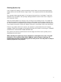
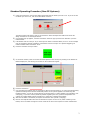
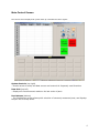
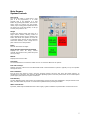
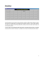
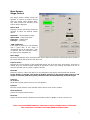
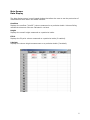
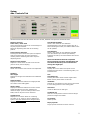
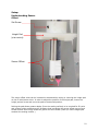
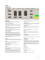
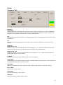
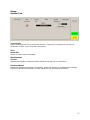
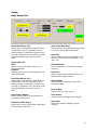
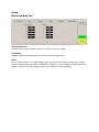
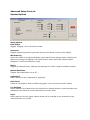
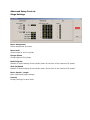
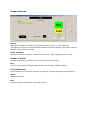
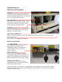
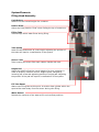
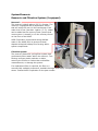
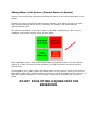
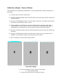
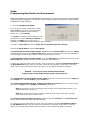
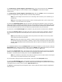
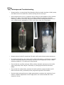
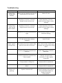
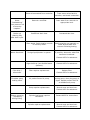
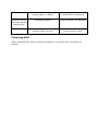
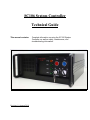
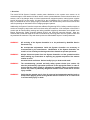
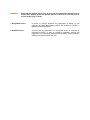
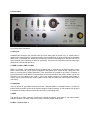
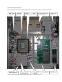
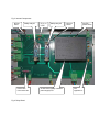
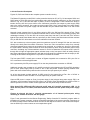
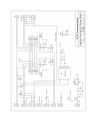
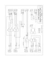
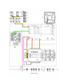
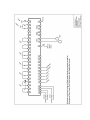
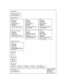
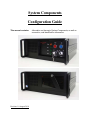
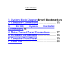
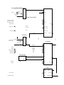
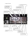
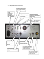
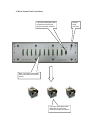
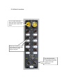
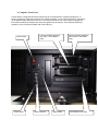
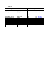
AVMS 2000 Automated Volume Measurement System System and Operation Manual AVID Corporation 222 International Drive / Suite 105 Portsmouth, NH 03801 (603) 559-9700 Copyright © 2011 1 Starting System Up From a power off condition, press and hold the power button on the uninterrupted power supply (UPS) until the UPS emits a single “beep.” The computer and I/O will automatically start. The computer takes approximately 1-2 minutes to boot up from a “cold state.” Login into Windows when prompted. User privilege settings should be set at Power User or higher to avoid program issues. Start the AVMS software by clicking on the shortcut on the desktop screen. The AVMS will prompt the operator to press either the Green or Blue button on the system controller. Do so. You will notice in the taskbar that the System Controller (I/O) connects to the computer via a network connection. When the System Controller is connected, click on the OK button. If there is a problem with the air source, the operator is presented with an Air Pressure message. Check the air supply to the system to ensure the system is receiving air. DAMAGE CAN OCCUR IF THE SYSTEM IS RUN WITHOUT AIR. The system will check the position and home all stages and fill the main cylinder prior to displaying the main screen. When starting the system up from a weekend or overnight of non-use, it is good practice to run a random bottle (500 -1000mL) once or twice to clear any air pockets that may have formed during the non-use period. You may wish to setup a simple program for this purpose. 2 Standard Operating Procedure (Non-CE Systems) 1) Using the touchscreen, click the part button associated with the bottle you wish to run. If you do not see the bottle you wish to run, click on the New Bottle # button. 2) 3) 4) The above window will appear. Click on the Get button. Select and Open the bottle from the file list. Assign the bottle to an unused part button. If a message pop-up appears, read the instructions within the pop-up and click on OK when you have followed them. Load bottles onto the conveyor. If you must open the doors to load the bottles, do so no. If the message pop-up suggested a specific orientation of the bottles onto the conveyor or a specific staggering, be certain to follow these instructions. Close Press the Run With Conveyor button. 5) In the feeder window, enter the number of bottles placed on the conveyor by clicking on the Number of Bottles display box, and entering the number on the touchscreen keypad. 6) Press the Run button. 7) It is generally good practice (but not required) to observe the first bottle run, to ensure that proper filling 8) 9) speeds and settings have not been accidentally altered. If the system appears to be measuring and handling properly, you do not need to observe the system further. If there appears to be a problem (nonemergency), try to note as many details as possible regarding the issue, press the Stop button and contact the certified AVMS system programmer or supervisor to address the problem. After the last bottle is measured, the system will refill the main cylinder (“charging”). Remove the emptied bottles from the bin beneath the system. If there is any water remaining in the bottles, return the water through the recover funnel at the front of the system to reduce wasted water. 3 Main Control Screen The control screen displayed at system start up is divided into three regions. System Controls (top right) - Permits access to setup and data screens and controls for frequently used functions. Data Grid (top left) - Displays the measurements made on the last series of parts. Part Buttons (bottom) - The Part Buttons section allows quick selection of commonly measured parts, and displays the part file currently active. 4 Main Screen: System Controls New Part # The new part button is used when a new part is to be programmed, or to recall program that is not assigned to a part button. By pressing this button, the user can either create an entirely new part profile, modify a pre-existing part template and save the values into a new part profile, or call up a saved part profile for use. Stages Pressing the Stages button will bring up a stage control window, allowing control of each individual motion device. Pressing this button also allows the operator to return all or selected motion devices to their individual home limit switches, move a single axis or place a device at its start position. Reset Re-links and homes all stages. Setup (Password Protected if enabled) Displays the menu for setup, volume nominal and tolerance entry, data setup and conveyor setup. Manual Displays this manual in PDF. Clear Data The clear data button will reset the bottle count to ‘0’ and clear data from the system. Run with Conveyor Displays conveyor control menu and associated feeder command buttons. System is typically run by the operator through this menu. Exit to Windows Exit will move the stages to home, close the program properly and then shut down the bottle program. To completely turn off power, shut down the Windows operating system. Press the power button on the uninterrupted power supply (UPS) after the system shuts down. Run Manually The Run Manually button will execute the measurement program for the part highlighted in the part buttons area. Note, the bottle MUST be present on measurement platform before pressing this button. Water Level Sensor If present, AVMS requires additional water. Add roughly 1 gallon of distilled or purified water via the front funnel. 5 Main Screen : Part Buttons The Part Buttons area of the Control Screen permits the selection of different part inspection routines with the press of a single button. This simplifies system operation when it is used by plant operators who might be unfamiliar with system setup. When a button is selected it will turn green and the associated part template file and setup parameters (including conveyor and data output setups) will be automatically loaded. To clear a button of its’ assigned part profile, right-click on it and erase the part number. To overwrite a button, assign a new part profile to the desired button. Overwriting the button does not overwrite the part profile it is linked to. Therefore, it is possible to have many more bottle profiles than buttons. 6 Main Screen: Stage Control The Stage Control window allows the operator to control all motion devices from one central menu location. Note, only those motion axis included on the system will be displayed. Motion Axis Pressing a motion axis button allows the operator to select the desired motion device. Dispenser – Main dispensing stage Spout Head – Filling tube stage Push Arm – Loading Arm Conveyor – Conveyor “LED” Indicators If the stage is powered, it will indicated with a green LED. If the stage is unpowered (due to an open door, fault or problem with the individual motor), the stage will be indicated red. Move Stage Allows the positioning of the selected motion device within it travel limit. Pressing the speed button in the center adjusts the speed the axis will move. Position # Box Displays the current position of the highlighted motion axis (from the home limit switch). If the box is clicked upon, the numeric keypad will pop-up and allow a value to be entered. This allows the user to send the selected axis to a point in space if desired. Reset All Resets the motor if a door was opened, or the Emergency Stop button was pressed and released. If this button is pressed, the Home All button should also be pressed after power to the stages is restored (LEDs turn green). Reset All does NOT automatically home all stages! Controls Go to Start Sends the selected motion device to its’ start position. Set Park Sets the current position of the selected motion device as the “park” position. Home Selected Homes the selected motion device. Home All Homes all motion devices. Should be pressed when system is RESET or when a fault occurs. NOTE: MOVING STAGES MANUALLY IN STAGE CONTROL DISABLES MOST FAILSAFES. PAY ATTENTION TO STAGE POSITIONS WHEN MOVING STAGES. 7 Main Screen: Data Display The data display screen is scroll based window that allows the user to see the past series of measurements from within the AVMS interface. Overflow Displays the overflow (“brimfill”) volume measured on a particular bottle. Volumes falling outside the tolerance value are indicated in red text. Height Displays the overall height measured on a particular bottle. Fill Pt Displays the fill-point volume measured on a particular bottle (if enabled). V Height Displays the volume height measurement on a particular bottle (if enabled). 8 Setup: Adv. Controls Tab The Advanced Controls Tab allows the user to test, calibrate and perform advanced tests. Dispense Controls Lower Tube / Raise Tube Lowers the dispensing tube to the nominal height of the part program selected. Raises the dispensing tube back to the starting position. Press to Active Dispense Pressing this button causes the system to dispense water through the tube as long as the button remains pressed. Releasing the button stops the dispensing action. Dispense Fixed Volume Dispenses a fixed volume of water from the tube (amount set by Volume display). Volume Display Allows user to set the fixed volume to be dispensed. Calibrate Std. Height Displays the height of the standard to be calibrated against. Platform Offset Displays the distance between the height pad and the surface of the loading plate. Sensor Offset Displays the distance between the sensor and the height pad affixed to the tube. Indicates the maximum depth (from the sealing surface of the bottle) that the fill point can be measured. Cylinder Scale Displays the conversion factor for measuring accurately in mL. Factor is used to calibrate the system. This value should not be changed unless advised to do so by AVID. Find Standard Height Starts a slow search for the calibration standard/artifact, using the Std. Height value as a basis. Following the search, the Platform Offset value will be updated. Find Meniscus Starts a slow search for the calibration standard (now brim filled as per customer specification). Following the search, the Sensor Offset value will be updated. Note: Find Standard should be completed before initiating Find Brim. Find Standard and Find Brim should always be conducted after moving the height pad. Probe State Displays the current state of the probe. Green indicates that the sensor is not detecting water, red indicated water. Test Find Bottle Top Pressing this button starts a bottle height search. Bottle must be placed under the fill tube. Get Bottle Indexes the next bottle from the conveyor and loads it to the filling position on the loading plate. Clear Data Clears all data from the data grid. Set Bottle Top Sets the current position of the fill tube and height pad as the height of the bottle. Fill Cylinder Refills cylinder. Empty Cylinder Purges cylinder contents into main reservoir. 9 Setup: Understanding Sensor Offset Set Screw Height Pad (size varies) Sensor Offset The sensor offset value can be increased or decreased by raising or lowering the height pad on the fill tube/sensor tube. In order to adjust the position of the height pad, loosen the height pad set-screw and move the pad to the desired position. Raising the pad allows greater depths (from the sealing surface) to be reached for fill-point and volume height measurements. Be aware that increasing the sensor offset may prevent smaller bottles from being measured (spout will strike bottle “push-up” before height pad contacts the sealing surface.) 10 Setup: Set Up Tab The Set Up Tab allows the operator to modify the height, volume limit settings, and testing settings for the bottle volume test. Specifications Overflow Volume Overflow volume nominal or target for the bottle. Overflow volume is also known as “brim” volume. Overflow Volume Checkbox If checked, AVMS will measure brim volume / overflow volume of the container, based on the brim volume nominal. Overflow Tol. Tolerance of the overflow volume nominal. (For example, if a bottle has overflow tolerance of +/- 5.0mL, the overflow volume tolerance should be set at 5.0). (Note: Larger brim volume tolerances will result in longer brim fill times.) O. Meniscus Offset Position of the fill sensor from the nominal height of the bottle. This position can be altered if the neck finish of the container creates a different filled meniscus than the calibration artifact. Positive brim meniscus values are above the sealing surface (and allow greater meniscuses than the calibrated meniscus to form), negative values are below the sealing surface (and allow smaller meniscuses than the calibrated meniscus to form). Fill Point Fill-point volume measurement allows the AVMS to measure the volume of the container when filled to a specified height. Height Displays the nominal height position (from the sealing surface) for fill-point volume measurements. Fill Point Checkbox If checked, AVMS will measure fill-point volume at the indicated height. Volume Nominal fill-point volume at the displayed height position. F. Meniscus Offset Position of the fill sensor from the nominal fill-point heights within the bottle. This position can be altered if the body of the container creates a different meniscus than the calibration artifact. Positive fill meniscus values are above the nominal fill-point (and allow greater meniscuses than the calibrated meniscus to form), negative values are below the nominal fill-point (and allow smaller meniscuses than the calibrated meniscus to form). Fill Volume Tol. Tolerance of the fill-point volume nominal. (For example, if a bottle has fill-point tolerance of +/- 5.0mL, the fill volume tolerance should be set at 5.0). Volume Height Volume height measurement allows the AVMS to measure the fill height of a container when filled with a known volume. (Note: Volume Height cannot be run while Fill Points are enabled, and vice-versa.) Volume If selected with the checkbox, system will dispense the indicated amounts then measure the fill height for each volume. Dispense Speed Speed at which water will be dispensed into the container. 100% is full speed. Speed will automatically slow when nearing target volumes. Bottle Height Displays the nominal height of container. Draining Time Amount of time (in seconds) bottle requires to drain once dropped into the recovery chute. Generally, containers with larger finish bottles (>38mm) require less time to drain than small finishes (<33mm). Experiment to determine the appropriate drain time for a particular bottle. (Note: short bottles may not drain completely if they land on their side in the chute.) Reset Resets system. Exit To Main Returns user to main screen. Save Setup Saves system settings (green values). Save Part Saves part specific settings (yellow values). 11 Setup: Transport Tab Conveyor Next Bottle Pressing this button will advance the next bottle until it reaches the electric eye / laser. Pressing this button will also call up the stage control window and automatically highlight the input conveyor. The operator can then advance the bottle to the proper loading position. Set Pressing this button sets the amount of movement required to move the bottle from the electric eye to the load arm. Go Pressing this button will advance the next bottle until it reaches the electric eye, then to the load position. Load Arm Load Pos Set / Go Allows the user to set the loading position of the loading arm. (i.e., pushes the bottle from the load point on the conveyor until it is centered under the fill tube on the loading plate.) Eject Pos Set / Go Allows the operator to set the ejecting position of the loading arm. (i.e., pushes the bottle from the loading plate into the recovery chute.) Go Home Pressing this button sends the load arm back to the start position. Load Speed Loading speed for the particular bottle program. Unstable bottles generally require a slower load speed to avoid being knocked over by the load arm. Open Eject Opens the pneumatic drain door under the system, allowing any bottles in the chute to fall out. Exit To Main Returns user to main screen. Save Setup Saves system settings (green values). Save Part Saves part specific settings (yellow values). 12 Setup: System Tab Touchscreen Allows recalibration of the touchscreen monitor. Pressing the crosshair will launch the calibration routine. Follow onscreen instructions. Files Bottle File Shows current bottle file selected. Miscellaneous Format: Displays the number of decimal places data and settings will be read out to. Password Reset Resets the password protection (if enabled). Allows the system to be password protected, preventing unauthorized access to setup parameters of the programmed files. 13 Setup: Data Setup Tab Excel Worksheet File… Allows users to designate a specific Excel worksheet to use in conjunction with a bottle program. If selected, whenever the part file is opened for use, the Excel sheet will automatically open and minimize itself. Upper Left Cell Row: Starting row cell for data output to an Excel worksheet. Column: Starting column cell for data output to an Excel worksheet. Excel Worksheet File… Allows users to designate a specific Excel worksheet to use in conjunction with a bottle program. If selected, whenever the part file is opened for use, the Excel sheet will automatically open and minimize itself. Excel Macro Names Allows certain Macros to be executed in Excel when data is sent. Enable for Data Input Allows user to turn on/off data exportation to the selected Excel file. Auto Clear Data Area Allows system to automatically wipe data from Excel sheet (Macro required.) Data File Allows output for the part program to be sent to remote data file (example, .csv, .dat, .txt). Data Delimiter Allows delimiter to be selected (usually comma). Data File Allows a particular destination file to be determined for data output. Send Header Allows header information to be sent along with data. Exit To Main Returns user to main screen. Save Setup Saves system settings (green values). Save Part Saves part specific settings (yellow values). 14 Setup: Measured Data Tab Fill Point Volume Displays extra volume measurements for the first 5 fill point tests. Vol Height Displays height measurements for the first 5 volume height tests. Note: Due to limited space in the data display grid, only the first fill-height volumes and volume height measurements are shown. Additional fill-height or volume height measurements will appear in Excel or the Data Output, but will not appear in the grid display. Advanced Setup Controls System Options Setup Options Data Status Toggles “flagging” of out-of-tolerance data. Password Toggles password protection (prevents access to the Setup controls of the AVMS). Windows File Allows the AVBIS to recognize Windows’ menu and font size settings (Note: enabling this feature can change formatting in the AVMS control menus and make certain buttons disappear or make text difficult to read). Metric Toggles all measurements, readings and settings into metric (requires software restart). Manual Save Data Toggles Save Data button on an off. Light Stack Allows system to use a lightstack (if equipped). Clear Parts Clears all part buttons. Does not delete programs, only removes the button names. I/O Settings Allows setting of the outputs from the controller to external devices. Values should not be changed by the customer unless instructed to do so by AVID. Input Allows setting of the air inputs. Values should not be changed by the customer unless instructed to do so by AVID. Advanced Setup Controls Stage Settings Motor Assignment Allows assignment of motors. Max Travel Stroke length of the fill cylinder. Charge Speed Charge speed of fill cylinder. Med Fill Speed Medium fill speed setting of the cylinder (taken as s divisor of the maximum fill speed). Slow Fill Speed Medium fill speed setting of the cylinder (taken as s divisor of the maximum fill speed). Motor Speed / Length Motor speed and length settings. Polarity Polarity settings for each motor. Advanced Setup Controls Misc Conversions Cylinder Offset Offset value to account for system “stiction” within the main cylinder. Set upon system delivery. I/O Controls Open Tank Opens the pneumatic controller to the tank. Open Dispense Opens the pneumatic controller to the dispensing tube. BackPressure On/Off Toggles backpressure setting to the cylinder to prevent “stiction.” Typically set to ON. Feeder Controls Bottles Displays the number of bottles as LED dots currently to be run. Yellow dots are unmeasured, red have volumes that fall outside of tolerance ranges, green have volumes that fall within tolerance ranges. Probe Indicator Displays the sensor condition of the fill-height sensor. Red is tripped, green is open. Number of Bottles: Displays the number of bottles to be run as a set on the conveyor. Run Runs the total number of bottles entered into the Number of Bottles display. Load (CE Systems) Allows bottles to be moved to the laser trip position, without having to open the doors. Reset Resets the system. Exit Exits the feeder window back to the main screen. System Elements Conveyor and Load Arm Conveyor AVMS uses a conveyor to index bottles into position for testing. Bottles should be set onto the conveyor against the rear conveyor rail, unless otherwise instructed. Recovery Chute Filled bottles fall neck first into the recovery chute where they are drained. After a set time to drain, bottom of recovery chute opens to release emptied bottles. Load Arm Moves empty bottles from conveyor to filling position. Moves filled bottles from filling position to recovery chute. Laser Sensor (Banner®) Used as a switch to inform system that a bottle has been detected. See information below. Recovery Funnel Allows water to be added to the system. Banner® Laser Sensor +/- Toggle Switch Cycles laser detection settings between dark (opaque containers), semitransparent bottles, and transparent (clear) bottles. “Clear” is the most sensitive setting. Signal Indicators The leftmost signal light box indicates unobstructed signal from the reflector. Any signal in the right two boxes indicates an object is present and will act as a “trigger.” Setting up Laser Sensor Ensure that the laser sensor has an unobstructed view of the reflector before setting up the laser sensor. Press and hold the + side of the +/- toggle switch until all lights go out. Release the toggle switch. The switch will perform a self-calibration for the reflector. The laser beam may grow brighter during the test. System Elements Filling Head Assembly Limit Switch Used to find the overall height of a container. Deltron Slide Allows the filling head to “float” when finding the top of containers. Filling Tube Tube through which water flows during filling. Tube Clamp Holds fill tube and sensor at a set height. Adjusting the position of the tubes will require a recalibration of the system. Sensor Tube Tube housing the sensor fiber optic cables. Handle with care. Height Pad Allows the AVMS to find the overall height of a given container in order to properly measure volume. Height can be changed by loosening set screw and adjusting position of height pad. Adjusting the position of the pad will require a recalibration of the system. Fill Tube Spout Water leave filling tube at this point. A smaller draw cylinder within the spout wicks water away from the sensor during slow filling. Water Sensor Detects the meniscus of the water at fill and overflow positions. System Elements Reservoir and Filtration System (if equipped) Reservoir The reservoir holds 6 gallons (22.7L) of water. The reservoir is equipped with a capacitance sensor that will notify the user via the touchscreen if the water level is low (less than 1 gallon / 3.7L). Water can be added via the recovery chute (ensure that recovery door is closed!) or via the recovery funnel on the front of the AVMS. AVID Corporation recommends using distilled water in the AVMS 2000 to prevent mineral deposits biological buildup from forming within system components. Filtration System The reservoir features a cycling filter system that continuously filters water within the reservoir. This filtering removes plastic particles or debris entering the fill tube or valves that could affect measurements, or damage the system. If a replacement filter is required, the filter is a commercially available component, available through most supply companies or hardware stores. Contact AVID Corporation for the part number. Adding Water to the System (Internal Reservoir System) System being supplied by local plant plumbing and sewer do not need to add water to the system. Despite the recovery chute and water recycling system, some water loss will occur with every bottle measured and is normal. Therefore, the system must occasionally be replenished with water. The system will indicate to the user if water is required by displaying a “water sensor” message in the system control menu, as seen below. While tap water may be used, AVID recommends using distilled water to fill the internal reservoir in order to prevent mineral deposits or biological buildup on internal system components. If prompted to do so, add 1 gallon of distilled water via the recovery funnel on the front of the system. After filling, give the system a moment to check the capacity of the reservoir. If filled, the indicator will turn off. If more water is required, the indicator will remain onscreen. DO NOT POUR OTHER LIQUIDS INTO THE RESERVOIR. Purging the System (Removing Contaminants) Only flat tap water or distilled water should be added to the system. NO SOAP OR CLEANING SOLUTION SHOULD EVER BE ADDED TO THE RESERVOIR! Should foreign liquids of any kind be introduced to the system, the reservoir and cylinder should be purged. 1) In Setup / Adv. Controls tab, press the Empty Cylinder button. Once completed, exit to Windows. 2) Turn off the AVMS and unplug the system from the electrical supply. 3) Remove the lower panels of the system to reveal the main reservoir tank and filtration system. Most systems have a release valve on the reservoir to assist draining. Drain the fluid into a container. 4) Unscrew the filter base from the filter head, and dispose of water in the filter. Dispose of the filter. 5) If necessary, rinse/clean all foreign liquids from the reservoir and filtration system. The pump powering the filtration system can be plugged into a standard 110V outlet to cycle water into and out of the filter component. 6) When cleaned, add fresh distilled or tap water to the reservoir. 7) Insert a new filter into the filtration system. 8) Turn the AVMS back on and start the volume software. 9) Place a large capacity container at the filling position. Lower the spout head into the container. 10) Enter a large fixed volume to dispense (1000mL is good) and press the Dispense Fixed Volume button. Contaminated water from the upper lines will now flow into the container (about 200mL) followed by now clean water from the reservoir. 11) Dispose of the contaminated line water, and cycle another into the container. Repeat two or three times, or until water exiting fill tube is clean. 12) When the water appears clear and uncontaminated, replenish the reservoir with clean distilled or tap water. Soaps, oils and other viscous substances may take longer to cycle out of the system. Blood, urine and any other bodily fluid found in the system voids warranty and will terminate further support and service contracts without refund. Calibration (Height / Sensor Offsets) If the position of the height pad is adjusted it is recommended that a height calibration be performed. 1) In Setup, go to the Adv. Controls tab. 2) Place the provided artifact under the filling tube, such that height pad will contact the “sealing surface.” 3) Press the “Find Standard” button. This will start a search for the artifact. Once found the system will prompt the user to Save. 4) Flip the artifact over and fill it to a proper brimfill position (generally flush with “sealing surface” of the artifact, however, this position is different among different manufacturers and customers). Use a syringe to achieve a desired meniscus. 5) Place the now filled artifact under the filling tube such that the sensor will contact the meniscus. 6) Press the “Find Meniscus” button. This will start a search for the meniscus on the standard. Once found the system will prompt the user to Save. 7) Once completed, press the Save Setup button. From Left to Right 1. Convex (meniscus too high, remove some water) 2. Flush (meniscus OK) 3. Concave (meniscus too low, add some water) Verification To verify the calibration with a known height standard, follow the above steps, then proceed with the following. 1) Create a new program called “Height Check” and assign it to a button. 2) In the Setup / Set Up tab, enter a bottle height equal to the height of the standard you will be verifying the system with. 3) Ensure that Overflow, Fill-Point and Volume Height checkboxes are all UNCHECKED. 4) Save the Part. Exit to Main. 5) Place the height block at the filling position, off to one side so the fill tube or sensor will not strike the block, but the height pad will contact the block. 6) Press the Run Manually button. 7) When complete, the height measurement will appear. If this number is within 0.010” of the nominal height of the block, the system is operating normally. If the number falls outside the 0.010” threshold, contact AVID for further support. Calibration (Volume) AVID Corporation recommends an annual or semi-annual calibration service be performed on the AVMS 2000 to ensure proper measurement and system function. If a third-party calibration is required, contact AVID Corporation to schedule a calibration service. However, a basic calibration can be performed by a trained system user. Using a calibrated weight scale, calibrated thermometer, and a large volume container (a 2000mL Erlenmeyer flask or other large volume container works well), follow the instructions below. 8) In Setup, go to the Adv. Controls tab. 9) Place the empty bottle on the weight scale and zero (tare) the scale. 10) Place the empty bottle underneath the fill tube. 11) In the Stages window, lower the Spout Head until the filling tube is just above the sealing surface of the bottle. 12) Under Dispense Controls, enter a fixed volume to dispense (500mL is convenient place to start). 13) Press the Dispense Fixed Volume button. The fixed volume entered will be dispensed into the container. 14) Record the temperature of the water now in the bottle. 15) Weigh the filled container. Using the weight with a water density/temperature conversion chart, determine the “actual” volume in the container. 16) If the “actual” volume in the container is LESS than stated dispensed volume from the AVMS, DECREASE the cylinder scale value, and press Save Setup button. If the “actual” volume in the container is MORE than stated dispensed volume from the AVMS, INCREASE the cylinder scale value, and press Save Setup button. 17) Dispense the same volume again and repeat the conversion procedure. When the value dispensed is within 0.3mL of “actual”, press the Save Setup button. Dispense larger or smaller volumes and check the amount against a conversion chart. If there is a discrepancy with larger or smaller volumes, contact AVID for assistance. Discussion: AVMS 2000 vs. Fill-Height Syringe Measurement The AVMS 2000 is able to measure fill-height volume by first locating the sealing surface of the container and then offsetting the fluid level sensor on the fill tube from the sealing surface a known distance (to the actual fill “height”). The AVMS then dispenses water until the fluid trips the sensor. Therefore, the fluid will actually reach the “fill-height” level. Fill-height volume measurements made using a fill-height syringe will often not agree with the AVMS 2000 fill-height volume measurements. However, the variation is generally constant. This is because fill-height syringes pull water from beneath their stated height, due to the vacuum forces of the devices. This can be proven by using a fill-height syringe, removing water from a container to the fill-height, remove and dry the syringe, and then place syringe back in the bottle. A gap will appear between the tip of the syringe and meniscus of the water. The fluid level in the bottle is therefore, NOT at the stated fill-height of the syringe. However, forcing the numbers to agree is simple if the customer requires the AVMS to reflect numbers that the fill-height syringe produces. In the Set Up tab of the Setup menu, change the value of the fill-height Meniscus Offset to a small negative value (generally between -0.050” and -0.150”.) This may require some experimentation to find the appropriate meniscus offset. Guide: Programming New Bottles for Measurement (New part programming and modification should only be performed by system programmers trained at AVID Corporation. This guide is a brief step-by-step instruction to refresh system programmers post-training.) 1) Press the New Bottle # Button. 2) If you wish to create a bottle from scratch, select Create. If you wish to use an existing bottle file as a template (similar features, heights, etc.), select Modify. 3) If Create is selected, give the bottle you are programming a unique filename. If Modify is selected, first Open a part file to use as a template, then Save with a unique filename when prompted. 4) Assign to a part button if desired. Place the correct bottle onto the conveyor. 5) Press the Setup Button. Press the Set Up tab. 6) If measuring overflow/brimfill volume, check the box for Brim Volume and enter the target overflow/brimfill volume in the Brim Volume display using the onscreen numerical entry tabulator. If not measuring overflow/brimfill volume, uncheck the box for brim volume. 7) If measuring overflow/brimfill volume, enter the tolerance for overflow/brimfill volume in the Brim Volume Tol. display using the onscreen numerical entry tabulator. 8) If the brim meniscus offset value is known, enter the positive or negative brim meniscus offset in the Brim Meniscus display using the onscreen numerical entry tabulator. If the value is unknown, observe the brim fill measurement when the bottle is run and adjust the offset if necessary. STEPS 9 – 11 are for fill-point volume measurements. If performing volume height measurements, skip to Step 12. 9a) If measuring a single fill-point volume, check the box for 1 fill-point and enter the target fillpoint Height for 1, and the target fill-point Volume for 1. 9b) If measuring multiple fill-point volumes (maximum of 5), check the box for each fill-point, and enter the target fill-point Height and Volume for each point. Note 1, fill-points must be in descending order of depth, from deepest/least volume (1) to shallowest/greatest volume (5). Note 2, fill-points cannot be set at depths greater than the sensor offset value (see Adv. Control tab to note Sensor offset value). 10) If measuring any fill-point volume(s), enter the fill-point tolerance in the Fill Volume Tol. display using the onscreen numerical entry tabulator. 11) If the fill meniscus offset value is known, enter the positive or negative fill meniscus offset in the Fill Meniscus display using the onscreen numerical entry tabulator. If the value is unknown, observe the fill-point measurement when the bottle is run and adjust the offset if necessary. 12) If measuring volume height(s) (maximum of 5), ensure that all Fill Points are checked in each box for each Height you wish to measure. Enter the Height for each volume height measurement. 13) If measuring volume height(s) (maximum of 5), enter the volume values to be dispensed in Volume Height Volume using the onscreen numerical entry tabulator. Note 1, Volume Height volumes must be in ascending order of amount, from smallest (1) to greatest (5). Note 2, Volume Height volumes cannot be set at volumes greater than 1) the volume of the container, or 2) the volume of the cylinder. 14) Enter the Dispensing Speed using the onscreen numerical entry tabulator. 100% is full power. AVID recommends a dispensing speed that does not create bubbles, foaming or backsplash that could accidentally trigger the sensor during filling and result in false volume measurements. Speeds should be set such that the bottle fills evenly and efficiently. Experimentation may be necessary. 15) Enter the nominal Bottle Height of the container using the onscreen numerical entry tabulator. 16) Enter the Draining Time for the bottle using the onscreen numerical entry tabulator. Draining time should be set to give the bottle adequate time to fully drain when dumped into the recovery chute. Note 1, small bottles may only partly drain if they land on their sides in the recovery chute. Some water loss should be expected. Note 2, bottles with smaller neck finishes (<33mm) should be expected to drain more slowly than bottles with large neck finishes (>38mm). Larger volume containers will also take longer to drain. Experimentation with the draining time may be required to determine an appropriate draining time. 17) CONVEYOR SETUP: Press the Transport tab. Ensure that the bottle is on the conveyor. Press the Next Bottle button. When the conveyor stops, go to the Stages menu. Select the Conveyor axis and advance the conveyor is placed in front of the loading “jaw.” Press the Set button. 19) Press the Load Pos Go button. The load arm will move the bottle from the conveyor to a default position. In the Stages menu, select the load arm axis and adjust the position until the neck finish of the bottle is centered under the filling tube. Press the Load Pos Set button. Note, if it is difficult to determine if the bottle is centered, lower the Spout Head in the Stages menu until you can better determine if the centering. 20) If the bottle is being moved too quickly/slowly, lower/raise the Load Speed setting. 21) Press the Eject Pos Go button. The load arm will move the bottle from the loading plate to an ejection position. In the Stages menu, select the load arm axis and adjust the position until the bottle is dumped into the recovery chute. Press the Eject Pos Set button 22) Save the bottle program by pressing Save Part, ensuring that the proper program is highlighted and press Save. Filling Tips, Technique and Troubleshooting Always perform a manual test (Run Manually) after the bottle has been initially setup and observe how the bottle fills, before running with the conveyor. Most measurement errors or problems during filling are attributable to filling speeds that are too high. If the bottle fills too violently (excessive splashing, foaming, bubbling), problems can occur during the measurement routine and cause errors or poor measurement repeatability. If this is the case, lower the filling speed. GOOD (even smooth fill) NOT GOOD (fill too fast) Always select a bottle fill speed that fills both swiftly and without undue turbulence. If a bottle starts filling, then stops quickly (before fill height or overflow are reached) and the filling head retracts, the sensor may have been tripped by a drop of water splashing upwards. Try lowering the filling speed. Ensure that the overflow meniscus offset yields a desirable meniscus on the bottle when completely filled. Adjust if necessary by changing the Overflow Meniscus Offset. Ensure that the load position presents the bottle perfectly centered under the fill tube and sensor tube, particularly when programming small finish bottles. Set the height pad position at a height appropriate to measure the majority of your bottles. Frequent adjustment of the height pad is not recommended due to the chance for errors. A small gap must exist between the fill tube and the sensor, or water will “leech” from the fill tube to the sensor and cause the sensor to “trip.” Water, metal components and electricity don’t mix. Mop up spills quickly. If water gets on stage components, dry them off with a clean dry cloth, then apply a light amount of WD-40 or other water repellent with a cloth to the components. If performing a gauge repeatability study, wet the bottles prior to starting as the AVMS does not completely dry the bottles post-test. The AVMS should never be placed in areas of high or heavy vibration or extreme temperature fluctuation as this will affect measurement accuracy and repeatability. Troubleshooting Problem Possible Cause Solution During filling, filling stops abruptly. Water may be splashing up from the empty base up to the sensor Reduce fill rate. Overflow, Fill-Point, or Volume Height volumes set too low. Check Overflow, Fill-Point, and/or Volume Height volume settings. Overflow, Fill-Point, or Volume Height volumes set too high. Check Overflow, Fill-Point, and/or Volume Height volume settings. Overflow or Fill-Point tolerances too tight. Check Overflow and/or Fill-Point tolerance settings. Fill rate set too high, causing “bubbling” Lower fill rate. Air bubbles forming in system after period of non-use (10+hours). Run a 500-1000mL bottle twice to purge any bubbles from filling tubes. Air being pulled into cylinder from reservoir. Check water level in reservoir. Add water. Air being pulled into cylinder from other location. Attempt to locate loose connection. If able, tighten connection. Foreign matter in filling line. Contact AVID for assistance. Other. Contact AVID for assistance. System Controller OFF. Check Emergency stop button. Press Green/Blue button on System Controller. Reset system. During filling, water surges above sensor. Water “spurts” during filling. Sensor not glowing. Sensor disconnected from controller. Trace sensor wires back to controller, and check connection. Water “backwashing” from reservoir out of recovery trapdoor. Reservoir overfilled. Drain water from reservoir to appropriate level. Bottle not draining fully after drain cycle. Insufficient drain time. Increase drain time. Short bottle. Bottle landing on side in recovery chute. Bottle must be run manually, or water drained back into reservoir following testing. Foreign liquid/matter in system. If possible, determine what fluid has been introduced. Water discolored. Contact AVID for assistance. Algae build-up (non-distilled water systems). Contact AVID for assistance. Filter dirty / discolored. Filter requires replacement. Replace filter. Contact AVID for assistance. Circulator pump making noise. Air pocket formed in pump. Unplug pump, then plug pump in again. Repeat process until all air bubbles exit pump. Pump requires replacement. Normal wear and tear item. Contact AVID for assistance. Cylinder lead screw requires lubrication. Contact AVID for instructions. Cylinder requires replacement. Normal wear and tear item. Contact AVID for assistance. System groaning / squeaking during filling. Meniscus’ forming incorrectly during measurement. Foreign matter in cylinder. Contact AVID for assistance. Calibration required. Check calibration with standard. Meniscus offset incorrect. Check meniscus offset. Contacting AVID When contact AVID for support, please be prepared to provide as much information as possible. SC106 System Controller Technical Guide This manual contains: Revision 1.0 August 2010 Complete information on using the SC106 System Controller, as well as safety, maintenance, and troubleshooting information. Table of Contents 1. Overview ........................ 38 2. Operator Controls .......... 39 2.1 E-Stop Lamp ............... 39 2.2 Door 1, Door 2, Door 3 Lamps .......................................................................................................................... 39 2.3 Reset Button ............... 39 2.4 Run Button ................. 40 2.5 Bypass Key Switch .... 40 2.6 Power Switch.............. 40 3. Operation ....................... 41 3.1 Normal System Startup41 3.2 Commissioning, Periodic and Daily Safety System Check ........................................................................... 41 4. Connections ................... 43 4.1 AC Input ...................... 43 4.2 PWR 1, COM 1, PWR 2, COM 2 ......................................................................................................................... 43 4.3 Computer .................... 43 4.4 EPO ............................. 43 4.5 Door 1, Door 2, Door 343 4.6 I/O Power .................... 44 4.7 Lamp Power................ 44 4.8 Lamp On/Off ............... 44 4.9 Camera LED................ 44 5. Internal Component Layout45 6. Circuit Function Description ................................................................................................................................... 47 7. Internal Calibration and Checks............................................................................................................................. 68 8. Parts List ........................ 69 1. Overview The model SC106 System Controller controls power distribution to the system servo motors on all motorized stages, to the attached I/O block device used to operate hardware such as solenoid valves and sensors, and to the halogen lamp in infrared measurement equipped systems. Internal power supplies provide 48 volts DC for the motors, 24 volts DC for the I/O hardware and 12 volts DC to the halogen lamp. An additional 24 volt DC power supply is dedicated to the internal safety control circuits and is also used for powering an illumination LED on imaging equipped systems. Additionally, the System Controller incorporates a Banner Engineering SC22-3 safety controller module to monitor an emergency-stop button and one to three safety door switches. A full description of the SC22-3 module and all relevant safety warnings and safety standard compliance declarations are available in the Banner Engineering “Safety Controller Models SC22-3 and SC22-3E Instruction Manual”. Most any machine state or fault that might be unsafe is neutralized by removing power from the system motors and any attached I/O hardware. Lamp and camera power are not disabled as part of a safety shutdown. WARNING! All servicing of the System Controller is to be performed by Qualified Service Personnel only. No user/operator adjustments inside the System Controller are necessary or recommended by the manufacturer. Modification of the System Controller can result in a loss of safety monitoring and serious hazards to operator personnel. WARNING! Always disconnect power from the System Controller and the guarded machine before making any connections or replacing any system component. Use extreme caution to avoid electrical shock at all times. Serious bodily injury or death could result. WARNING! The commissioning, periodic and daily safety system checks (see section 3.2) must be performed by appropriate personnel at the appropriate times in order to ensure that the safety system is operating as intended. Failure to perform these checks may create a potentially dangerous situation which could lead to serious injury or death. WARNING! Verify that the guarded area is clear of personnel and unwanted materials (such as tools) before applying power to the guarded machine. Failure to do so could result in serious bodily injury or death. 2. Operator Controls Fig. 1 Front Panel Controls 2.1 E-Stop Lamp Amber colored and when illuminated indicates that the emergency stop button has been activated. Power to the motors and I/O hardware is removed. 2.2 Door 1, Door 2, Door 3 Lamps Green colored and when illuminated indicate that a corresponding guard door 1,2 or 3 is open. Power to the motors and I/O hardware is removed. 2.3 Reset Button Red colored illuminated pushbutton. Resets the safety controller module. This will only light in the event of a serious internal malfunction such as welded or stuck safety relay contacts or failure of the safety controller module itself. A “soft” error may correct itself by actuating the button. WARNING! If the red Reset button light stays on the system must not be used and the Power Switch should be rotated to the Off position. Alert the Safety Officer of the situation. 2.4 Run Button Blue colored illuminated pushbutton. When lit indicates that the system controller is ready to be activated. Then pressing the button will enable the motor and I/O hardware power outputs. WARNING! When performing the system run operation, it is the user’s responsibility to make sure that all potential hazards are clear and free of people and unwanted materials (such as tools) that could be exposed to the hazard. Failure to do so could result in serious bodily injury or death. 2.5 Bypass Key Switch Key operated bypass switch that allows unrestricted guard door operation for testing and maintenance purposes by Qualified Service Personnel only for up to a maximum of 30 minutes. Doors may be opened without loss of power to the motors and I/O hardware. The emergency stop button remains fully operational. After 30 minutes, if any guard door has been previously opened power to the motors and I/O hardware will be removed. Normal full safety monitoring is enabled. The switch should normally be in the Off position at all times. The switch keys should be kept in the sole possession of the responsible Safety Officer. 2.6 Power Switch Powers the system controller On and Off. When rotated to Off all power outputs are shut down. 3. Operation 3.1 Normal System Startup 1. To turn on the system the operator should first check that all guard doors are closed and that the emergency stop button is not actuated. 2. Then rotate the Power switch to the On position. 3. Wait for the blue Run button to light. No other indicator should be lit. Observe all warnings cited in section 2. 4. Press the Run button momentarily. 5. The blue Run button light should extinguish and power will be applied to the motors and I/O hardware. 6. To turn off the system controller, rotate the Power switch to the Off position at any time. 3.2 Commissioning, Periodic and Daily Safety System Check 1. Turn on the system as described in section 3.1 above. 2. Activate the system E-Stop switch. Verify that the front panel E-Stop indicator lamp is lit. Verify that motor power is removed by checking that both LED’s on each system servo motor are extinguished. Verify that I/O power is removed by checking that all LED’s on the system I/O block are extinguished. 3. Deactivate the system E-Stop switch. Verify that the front panel E-Stop indicator lamp is extinguished. The blue Run button should light. Press the Run button momentarily. The blue Run button light should extinguish and verify that power is applied to the motors and I/O hardware. 4. Repeat steps 2 and 3 using in turn each guard door switch and corresponding front panel door indicator instead of and identically to the E-Stop switch and E-Stop front panel indicator. 2 Commissioning Checkout : A Qualified Person must perform the safety system commissioning procedure above before the safeguarded machine application is placed into service and after the internal Safety Controller module configuration is created or modified. 2 Periodic (Semi-Annual) Checkout : A Qualified Person must also perform a safety system recommissioning semiannually (every 6 months) or at periodic intervals based on the appropriate local or national regulations. 1 Daily Operational Checks : A Designated Person must also check the effectiveness of the protective devices each day that the safeguarded machine is in service. WARNING! The commissioning, periodic and daily safety system checks must be performed by appropriate personnel at the appropriate times (as described above) in order to ensure that the safety system is operating as intended. Failure to perform these checks may create a potentially dangerous situation which could lead to serious injury or death. WARNING! If all of these checks cannot be verified, do not attempt to use the safety system that includes the System Controller and the guarded machine until the defect or problem has been corrected. Attempts to use the guarded machine under such conditions could result in serious bodily injury or death. WARNING! Verify that the guarded area is clear of personnel and unwanted materials (such as tools) before applying power the guarded machine. Failure to do so could result in serious bodily injury or death. 1. Designated Person : A person or persons identified and designated in writing, by the employer, as being appropriately trained and qualified to perform a specified checkout procedure. 2. Qualified Person : A person who, by possession of a recognized degree or certificate of professional training, or who, by extensive knowledge, training and experience, has successfully demonstrated the ability to solve problems relating to the subject matter and work. 4. Connections Fig. 2 Back Panel Connectors 4.1 AC Input Unlabelled and located to the extreme lower left on the back panel as shown in Fig. 2. Mains power is applied to the male IEC320-C13 connector portion of this combination AC input module with a compatible power cord. A removable fuse drawer is just above the connector containing two 5 amp 250 volt 5 X 20 mm fast acting fuses (Littlefuse 217005H or equivalent). The power source must be 100-240 VAC single phase at 50 or 60 Hz with ground pin. 4.2 PWR 1, COM 1, PWR 2, COM 2 PWR 1 is a female 7 pin combination D-Dub connector that is connected to the PWR connector on the Motor Fanout Panel. 48 volt DC power is supplied to the system servo motors on the 2 large pins. This power is removed during safety shutdowns. Three small pins are jumped to the COM 1 connector to provide bidirectional serial RS232 communications to the motors as well. The COM 1 female 9 pin D-Sub connector is in turn cabled to the “Com 1” port of the system computer. An optional second bank of motors may be implemented with another Motor Fanout Panel and using the similar PWR 2 and COM 2 connectors. 4.3 Computer This is a female “B” type USB connector used with a standard USB 2.0 compatible cable to connect the internal safety controller module to the system computer. Support software on the computer can be used to configure the safety controller module and to monitor it’s operating state. 4.4 EPO This female 4 pin M12 connector connects the external emergency stop switch to the internal safety controller module. The switch must have 2 poles of normally closed contact pairs. 4.5 Door 1, Door 2, Door 3 These female 4 pin M8 connectors attach to the system guard door switches. Magnetically coded switches are used, each with a normally closed and a normally open pair of coordinated reed switch contacts. 4.6 I/O Power This female 5 pin “7/8 inch” connector provides 24 volt DC power at up to 60 watts to attached general purpose input/output hardware. An intelligent I/O block with compatible connector is normally used, which communicates with the system computer over an Ethernet link using the Modbus /TCP protocol. This module is then attached to various product-specific control components as needed, such as air or water solenoid valves, relays, sensors, etc. This power is removed during safety shutdowns. 4.7 Lamp Power This female 4 pin M12 connector connects to an external halogen lamp in infrared measurement equipped systems. 12 volt DC power at up to 30 watts is provided on two separate wire pairs. 4.8 Lamp On/Off This male 3 pin M8 connector is normally attached to an IR controller in infrared measurement equipped systems. Only 2 of the 3 pins are used to apply a 3 to 32 volt DC control signal to a solid state relay in the system controller that connects and disconnects power to the Lamp Power connector. 4.9 Camera LED This female 3 pin M8 connector is normally attached to an illumination LED on imaging equipped systems. Only 2 of the 3 pins are used to apply 24 volt DC power to the LED through an included 1K ohm current limiting resistor. 5. Internal Component Layout Refer to figures 3 and 4 for the layout and identification of the major system controller components. Back panel connectors Terminal block TB1 24 VDC 60 W I/O power supply PS2 SC22-3 safety controller module SC1 12 VDC 30W lamp power supply PS3 48 volt servo motor power supply PS4 Lamp On/Off relay K4 Relay board Front panel controls 12 VDC Fan Fig. 3 Internal Components AC line LED1 Safety relay K1 Camera LED current limiter R5 Fig. 4 Relay Board K1 is on LED3 Safety relay K2 24 VDC 40 W Safety controller power supply PS1 K2 is on LED4 24 VDC power LED2 Fan regulator U1 6. Circuit Function Description Figures 5a, 5b,5c and 5d show the complete system controller circuitry. The Banner Engineering model SC22-3 safety controller labeled as SC1 in Fig. 5c has outputs SO1A and SO1B wired to JCoil that drive force-guide safety relay coils K1 and K2 respectively on the relay board shown in Fig. 5a. K1 and K2 each have 2 poles in a DPST configuration. These contacts are wired in tandem from the AC line input at JACin to the JACmotors connector (line output to power supply PS4) and to the JACIO connector (line output to power supply PS2). Servo motor power from power supply PS4 and I/O power from power supply PS2 will therefore only be enabled when both of K1 and K2 are activated. Normally closed contacts from K1 and K2 are wired to SC1 pins S20 and S21 through JFault. These contacts are monitored by SC1 to determine whether the K1 and K2 relays are functioning properly with undamaged contacts. If not, then SC1 will remove power from both the K1 and K2 coils. SC1 will then light the front panel Reset button with an output from pin O6. Pressing the Reset button will then activate SC1 pin SR and SC1 will recheck to see if the malfunction has been cleared. SC1 also monitors up to three system guard door switches at pins S5 through S13 that are connected directly to the back panel door switch connectors. These are 3-wire connections to allow for a normally closed and normally open contact in each switch to be monitored. In a similar way, pins S1 to S4 monitor the system DPST normally closed contacts of the E-Stop switch by direct wiring to the back panel E-Stop connector. Activating any of these switches causes K1 and K2 to deactivate and outputs at SC1 pins O1 through O4 will light the appropriate status indicator lamp on the front panel. When all safety switches have been subsequently deactivated SC1 will light the front panel Run pushbutton with the output pin O5. Pressing the Run button will signal SC1 at pin S22 to reactivate K1 and K2. The front panel DPST normally open contacts of Bypass keyswitch are connected to SC1 pins S14 to S17 to monitor the selected bypass state. SC1 is powered by 24 VDC power supply PS1 on the relay board with a connection to JSC24V. Additional normally open contacts on K1 and K2 are wired in series between the RC and RCG shutdown pins of motor power supply PS4 by means of JRC of the relay board. Contact opening disables motor power with a much faster decay than the sole removal of line input power by K1 and K2. U1 of the relay board provides optional 12 VDC power for the system fan at JFan. One of JP24V or JP12V are shorted to select 24 VDC or 12 VDC respectively for power to the fan. Camera LED power is output at JCam, line power input for the halogen lamp power supply PS3 is at JACLamp, and front panel control 24 VDC power is at JFP24V. Relay K4 switches line power to PS3 on and off by means of a 3-32 volt DC control signal from the rear panel Lamp On/Off connector. Relay board LEDs LED3 and LED4 show the on/off state of K1 and K2 respectively, LED 1 is lit when AC line power is at JACin, and LED2 monitors onboard 24 VDC power from power supply PS1. Figures 6a through 6d show a pictorial representation of all internal point-to-point wiring according to subsets of function and wire gauge. Figure 7 was generated from the Banner Engineering “Safety Controller PC Interface” program which is installed on the system computer. It shows a simplified schematic of the system controller connections to the SC22-3 safety module. Different labels are used in that diagram for some of the controls and outputs. Use the SC22-3 pin number names as a correspondence guide. Figure 8 provides a summary of the detailed functionality that has been programmed into the SC22-3 safety module. This was also generated from the Banner Engineering “Safety Controller PC Interface” program. Symbol names are matched to those in figure 7. Fig. 5a Relay Board schematic Fig. 5b Power distribution schematic Fig. 5c Safety circuitry schematic Fig. 5d Motor Power/COM board schematic Fig. 6a AC wiring Fig. 6b Ground wiring Fig. 6c Low voltage wiring Fig. 6d Signal, control and external power output wiring Fig. 7 Safety controller simplified schematic Fig. 8 Safety controller configuration summary 7. Internal Calibration and Checks 1. Remove the chassis top cover by removing the 4 topmost screws on the side rails (2 on each side). Then pull the cover to the rear about ½ inch and then up and away. Refer to figures 3 and 4 for the layout and identification of the internal system controller components. 2. Power up the controller in the normal run mode as per section 3. 3. Adjust the DC output voltage of power supply PS4 to 46.0 volts (down from the nominal 48.0 volts). 4. Activate Lamp On/Off relay K4. Adjust the DC output voltage of power supply PS3 to 11.0 volts (down from the nominal 12.0 volts). 5. Adjust the DC output voltage of power supply PS2 to 24.0 volts. 6. Confirm that all 4 LEDs are illuminated on the relay board. Check for 24 +/- 0.5 volts DC at JSC24V on the relay board. With JP12V jumpered and JP24V open on the relay board check for 12 +/- 0.5 volts DC at JFan. Move the jumper to JP24V if the fan is 24 volt. 7. Momentarily jump either pin of JFault on the relay board to R5 on the end closest to JCoil. LED3 and LED4 should extinguish. Relays K1 and K2 should deactivate. The power LEDs on PS2 and PS4 should also extinguish. The red Reset pushbutton on the front panel should light and stay lit. Press the Reset button and its lamp should extinguish. Repeat the previous with the other pin of JFault jumped to R5. 8. Parts List Description Chassis Cabinet, rack mount, 4U Panel, back Panel, base adapter Panel, base Panel, front Panel, laser blank Fan guard, 60mm DIN rail, 35mm, 1M long Fan, 12VDC, 120 X 120 X 25 mm Screw, flat head, M3 X 6mm, SS Screw, flat head, M4 X 6mm, SS Screw, flat head, M4 X 20mm, SS Screw, flat head, 8-32, 5/16", SS Screw, socket, 1/4-20, 5/16" SS Screw, socket, 8-32, 1/4" , oxide Screw, socket, 8-32, 5/8" , oxide Screw, phil, 6-32, 3/8" , SS Screw, phil, 6-32, 3/8" , SS+oxide Screw, phil, 8-32, 3/8" , SS Screw, phil, 8-32, 3/4" , SS Bracket, 11/16"x1"x1/2", steel Standoff, 8-32, F-F, 1/2", 3/8" hex Washer, #10, thick, oxide Washer, #10, SS Washer, M4, SS Washer, split lock, M4, SS Nut, hex, M4, SS Nut, hex, #6, tooth washer, SS Nut, hex, #10, tooth washer, SS Mfr. Part # Mfr. SL-CASE-R4U SuperLogics Controller_Back_R2.fpd AVID Controller_Base_Adapter_R1.fpd AVID Controller_Base_R2.fpd AVID Controller_Front_R2.fpd AVID Controller_Laser_Blank_R0.fpd AVID Qty. 1 1 1 1 1 1 1 1 1 4 4 1 3 6 3 1 13 2 6 1 1 3 3 1 1 1 1 2 1 CE Data Source DF121225BM Dynatron Power Supplies Power supply, 12 VDC, 2.5 A, 30W PS5R-SC12 Power supply, 24 VDC, 2.5 A, 60W PS5R-SD24 Power supply, 48VDC, 10A PFC500W-48 IDEC IDEC Animatics 1 1 1 Yes Data Sheet Yes Data Sheet Yes Data Sheet Safety Controller Safety Controller Banner 1 Yes Instruction Manual Front panel controls SC22-3 Yes Data Sheet Switch, head, short lever, 2 pos. Switch, 3 position clip Switch contact block, SPST, NO Switch contact block, SPST, NO Switch, head, key, 2 pos. Switch, 3 position clip Switch contact block, SPST, NO Switch contact block, SPST, NO Switch, head, round, mom., red Switch, 3 position clip Switch contact block, SPST, NO Switch, LED block, red Switch, head, round, mom., blue Switch, 3 position clip Switch contact block, SPST, NO Switch, LED block, blue Indicator LED, 13mm, green Indicator LED, 13mm, amber L21KA03 333E 33E10 33E10 L21LA00 333E 33E10 33E10 L21AH10 333E 33E10 33EARL L21AH60 333E 33E10 33EABL 13SBLG24ST-13GNF 13SBLG24ST-13GNF BACO Controls BACO Controls BACO Controls BACO Controls BACO Controls BACO Controls BACO Controls BACO Controls BACO Controls BACO Controls BACO Controls BACO Controls BACO Controls BACO Controls BACO Controls BACO Controls C3 Controls C3 Controls 1 1 1 1 1 1 1 1 1 1 1 1 1 1 1 1 3 1 Wiring Wire duct, slotted, PVC, 1/2" X 1" Screw clamp block, 6mm, yellow Screw clamp block, 6mm, black End section, gray End stop Cable, USB 2.0, 3 ft M4/6 M4/6 FEM6 BAM2 USB2HAB3 Entrelec Entrelec Entrelec Entrelec StarTech 1 1 1 1 3 1 Relays Relay, SSR, SPST, 10A, 280VAC 861SSR210-DC-1 Magnecraft 1 Relay Board Relay Board PC board Relay, 4PST, 6A, 24VDC coil Socket, relay, PCB mount Power supply, 24 VDC, 40W Terminal block, 2-pin Terminal header, 2-pin Terminal block, 3-pin Terminal header, 3-pin Resistor, carbon film, 1K, 5%, 2W Resistor, carb film, 100K, 5%, 1W Regulator, 12V, 1 A, SIP Capacitor, 10uf, 20V, tantalum Capacitor, 47uf, 35V, tantalum Diode, 600V, 1A AVSCRB Rev. 1.0 G7SA-3A1B-DC24 P7SA-10P RAC40-24SA 1840366 1844210 1757022 1757255 ON1025E OM1045E R-78B12-1.0 TAP106K020SCS TAP476K035CCS 1N4005-E3/54 AVID STI STI Recom Phoenix Phoenix Phoenix Phoenix Ohmite Ohmite Recom AVX AVX Vishay 1 2 2 1 7 7 4 4 1 1 1 1 1 3 Yes Yes Yes Yes Yes Yes Yes Yes Yes Yes Yes Yes Yes Yes Yes Yes Yes Yes Catalog Catalog Catalog Catalog Catalog Catalog Catalog Catalog Catalog Catalog Catalog Catalog Catalog Catalog Catalog Catalog Data Sheet Data Sheet Yes Data Sheet Data Sheet Data Sheet Yes Data Sheet Data Sheet Data Sheet Data Sheet Data Sheet Data Sheet LED, red, short lens, diffused LED, amber, short lens, diffused LED, green, short lens, diffused Resistor, 4.75K, 1/4W, 1%, m. film Capacitor, .1uf, 50V, ceramic Header, 2-pin, dual row Jumper Back Panel Connectors Connector, USB, panel mount Connector, M8, 3-pole, F Connector, M8, 3-pole, M Connector, M8, 4-pole, F Connector, M12, 4-pole, F, dual key Connector, M12, 4-pole, F, one key Connector, 7/8, 5-pole, F, one key Cable, USB 2, 1 ft, A-male B-male Motor Connector Board Jackscrews, 4-40, 3/16" thd length Connector, PC, D-sub, 9 pin female Connector, PC, D-sub mixed female Terminal block, 2-pin Power Entry module Fuse drawer Fuse, 5A/250V, 5X20mm, fast act SSL-LX3044ID SSL-LX3044AD SSL-LX3044GD MFR-25FBF-4K75 SR155E104MAR PBC01DFAN Lumex Lumex Lumex YAGEO AVX Sullins 1 2 1 3 2 2 1 PX0842/B 4R3P00A27C300 4R3P06A27C300 4R4P00A27C300 7R4A00A19A120 8R4A00A18A120 1R5004A20A120 USB2HAB1 AVJOIN Bulgin Brad-Harrison Brad-Harrison Brad-Harrison Brad-Harrison Brad-Harrison Brad-Harrison StarTech AVID MD9F3S600X-929.2 CBD7W2F35S600X 1714955 4303.0001 4303.2401 217005H Positronics Positronics Phoenix Schurter Schurter LittleFuse 1 1 1 3 1 1 1 1 1 8 2 2 1 1 1 2 Data Sheet Data Sheet Data Sheet Data Sheet Data Sheet Data Sheet Data Sheet Catalog Catalog Data Sheet Data Sheet Data Sheet Data Sheet System Components Configuration Guide This manual contains: Revision 1.0 August 2010 Information on the major System Components, as well as connection, and identification information. Table of Contents 1. System Block DiagramError! Bookmark no 2. Computer Connections ........................ 75 3. SC106 System Controller Connections.76 4. Motor Fanout Panel Connections ........ 77 5. I/O Block Connections ......................... 78 6. Computer Front Panel .......................... 79 7. Parts List .............................................. 80 1. System Block Diagram 1 PWR Motors PWR 1 RS232 48 VDC COM 1 RS232 9 Motor Fanout Panel Door 1 Guard Door 1 Switch Guard Door 2 Switch Door 2 Guard Door 3 Switch Door 3 E Stop Switch - EPO 12 VDC Halogen Lamp Lamp Power 3-32 VDC IR Controller Lamp On/Off Lamp On/Off 20 ma Camera LED Line In Camera LED 24 VDC I/O Power Computer I/O Block Solenoid valves, Sensors, etc. U B S RS232 PWR 8 24 V Outputs Computer 8 24 V Inputs Link "A" Ethernet USB Camera Ethernet Network RS232 Auxiliary Gauge RS232 Weight Scale USB IR Controller USB "W" USB RJ45 "T" "S" USB Touchscreen VGA Video VGA "U" Line In Serial I/O RS232 "M" PS2 Mouse PS2 Line In RS232 Keyboard UPS Battery Battery Backed Out Backed Out AC Line Power Rack Safety Switch Line In EPO Serial I/O Bypassed Out 2. Computer Connections “T” – DB9 serial cable connection to auxiliary hardware “A” – DB9 serial cable connection to the SC106 system controller COM 1 “S” – DB9 serial cable connection to the weight scale VGA DB15 cable connection to the touchscreen monitor Customer RJ45 ethernet cable connection for the network IEC 320-C13 AC line input cord to a UPS battery backup outlet USB connectors “M” – DB9 serial cable connection to the touchscreen monitor PS2 type keyboard and mouse connectors “U” – DB9 serial cable connection to the UPS “W” – RJ45 ethernet cable connection to the I/O Block 3. SC106 System Controller Connections IEC 320-C13 AC line input cord to a UPS non-battery backup outlet 3-pin female M8 cable connection to the camera illumination LED 7-pin female mixed Dsub cable connection to the motor fanout panel PWR input connector DB9 female serial cable connection to the computer “A” DB9 connector USB “B” cable connection to any computer USB port Three female 4-pin M8 cable connections to the system guard door switches 4/5-pin female single-key M12 cable connection to the E-Stop switch 3-pin male M8 cable connection to the IR Controller Lamp On/Off 4-pin dual-key female M12 cable connection to the IR system halogen lamp 5-pin female 7/8” mini cable connection to the I/O block 24 VDC power input 4. Motor Fanout Panel Connections 7-pin male mixed Dsub cable connection to the SC106 System Controller at PWR 1 Nine 7-pin female mixed Dsub cable connections to the servo motors 7-pin male mixed Dsub cable connection to one-of-nine motor fanout panel connectors Unused COM connector 5. I/O Block Connections 7/8” mini male cable power input connection to the System Controller power output at I/O Power Eight 4-pin female M12 cable connections for 8 input and 8 output 24 VDC general purpose I/O ports Two 4-pin female M12 ethernet cable connectors – connect either one to the computer “W” RJ45 ethernet port 6. Computer Front Panel The two RAID 1 configured hard drives should only be removed with the computer powered off. To remove a hard drive rotate the barrel key lock counter-clockwise ¼ turn on the drive drawer. Then lift up on the drawer handle and pull the drive out. To insert the drive push it in until it begins to engage and then lower the handle to complete the entry. Only gentle force is required. Then rotate the barrel key clockwise ¼ turn on the drive drawer and remove the key. Reset switch Power switch Lower removable hard drive bay. Drive 1 in the RAID 1 array. USB connectors Status LEDs Upper removable hard drive bay. Drive 0 in the RAID 1 array. DVD ROM or R/W drive 7. Parts List Description Mfr. Part # Mfr. Qty. CE Data Source Computer Power supply Motherboard Hard drive DVD RAM drive Serial I/O Board, 4 port, PCI Ethernet board, 10/100, PCI Graphics board Fan, 12VDC, 120 X 120 X 25 mm FSP550-60PLG DP43BF ST380815AS SH-223L QUATTRO-PCI F5D5000 512-P3-1213-LR DF121225BM Sparkle Power Inc. Intel Seagate Samsung Lava Belkin EVGA Dynatron 1 1 2 1 1 1 1 1 UPS UPS SMX500RT1U Tripp-Lite 1 Yes Data Sheet Motors Servo Motor, 1-stack, 2000 count SM2315D Animatics 9 Yes Catalog Yes Yes Yes Yes Yes Yes Yes Yes Data Sheet Data Sheet Data Sheet User Guide Data Sheet User Manual Data Sheet Data Sheet