1
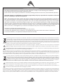
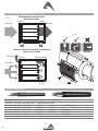
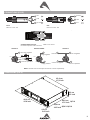
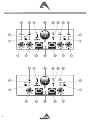
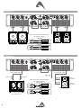
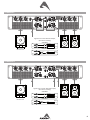
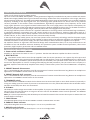
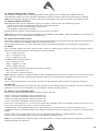
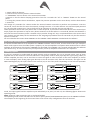
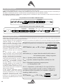
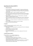
QC series QC4.2 - QC4.4 - QC2.4 Digitally Controlled Class D Power Amplifiers with SMPS & DSP USER MANUAL FCC COMPLIANCE NOTICE This device complies with part 15 of the FCC rules. Operation is subject to the following two conditions: (1) This device may not cause harmful interference, and (2) this device must accept any interference received, including interference that may cause undesired operation. CAUTION: Changes or modifications not expressly approved by the party responsible for compliance could void the user’s authority to operate the equipment. NOTE: This equipment has been tested and found to comply with the limits for a Class B digital device, pursuant to part 15 of the FCC Rules. These limits are designed to provide reasonable protection against harmful interference in a residential installation. This equipment generates, uses, and can radiate radio frequency energy and, if not installed and used in accordance with the instruction manual, may cause harmful interference to radio communications. However, there is no guarantee that interference will not occur in a particular installation. If this equipment does cause harmful interference to radio or television reception, which can be determined by turning the equipment off and on, the user is encouraged to try to correct the interference by one or more of the following measures: • Reorient or relocate the receiving antenna. • Increase the separation between the equipment and receiver. • Connect the equipment into an outlet on a circuit different from that to which the receiver is connected. • Consult the dealer or an experienced radio/TV technician for help. This marking shown on the product or its literature, indicates that it should not be disposed with other household wastes at the end of its working life. To prevent possible harm to the environment or human health from uncontrolled waste disposal, please separate this from other types of wastes and recycle it responsibly to promote the sustainable reuse of material resources. Household users should contact either the retailer where they purchased this product, or their local government office, for details of where and how they can take this item for environmentally safe recycling. Business users should contact their supplier and check the terms and conditions of the purchase contract. This product should not be mixed with other commercial wastes for disposal. The lightning flash with arrowhead symbol within an equilateral triangle is intended to alert the user to the presence of uninsulated “dangerous voltage” within the product’s enclosure, that may be of sufficient magnitude to constitute a risk of electric shock to persons. The exclamation point within an equilateral triangle is intended to alert the user to the presence of important operating and maintenance (servicing) instructions in the literature accompanying the appliance. The information contained in this publication has been carefully prepared and checked. However no responsibility will be taken for any errors. All rights are reserved and this document cannot be copied, photocopied or reproduced in part or completely without written consent being obtained in advance from PROEL. PROEL reserves the right to make any aesthetic, functional or design modification to any of its products without any prior notice. PROEL assumes no responsibility for the use or application of the products or circuits described herein. Il marchio riportato sul prodotto o sulla documentazione indica che il prodotto non deve essere smaltito con altri rifiuti domestici al termine del ciclo di vita. Per evitare eventuali danni all’ambiente si invita l’utente a separare questo prodotto da altri tipi di rifiuti e di riciclarlo in maniera responsabile per favorire il riutilizzo sostenibile delle risorse materiali. Gli utenti domestici sono invitati a contattare il rivenditore presso il quale è stato acquistato il prodotto o l’ufficio locale preposto per tutte le informazioni relative alla raccolta differenziata e al riciclaggio per questo tipo di prodotto. Gli utenti aziendali sono invitati a contattare il proprio fornitore e verificare i termini e le condizioni del contratto di acquisto. Questo prodotto non deve essere smaltito unitamente ad altri rifiuti commerciali. Il simbolo del lampo con freccia in un triangolo equilatero intende avvertire l'utilizzatore per la presenza di "tensioni pericolose" non isolate all'interno dell'involucro del prodotto, che possono avere una intensità sufficiente a costituire rischio di scossa elettrica alle persone. Il punto esclamativo in un triangolo equilatero intende avvertire l'utilizzatore per la presenza di importanti istruzioni per l'utilizzo e la manutenzione nella documentazione che accompagna il prodotto. Le informazioni contenute in questo documento sono state attentamente redatte e controllate. Tuttavia non è assunta alcuna responsabilità per eventuali inesattezze. Tutti i diritti sono riservati e questo documento non può essere copiato, fotocopiato, riprodotto per intero o in parte senza previo consenso scritto della PROEL. PROEL si riserva il diritto di apportare senza preavviso cambiamenti e modifiche estetiche, funzionali o di design a ciascun proprio prodotto. PROEL non assume alcuna responsabilità sull’uso o sul l’applicazione dei prodotti o dei circuiti qui descritti. INDEX FCC COMPLIANCE NOTICE. . . . . . . . . . . . . . . . . . . . 2 TECHNICAL SPECIFICATIONS . . . . . . . . . . . . . . . . . . 3 SETUP AND RACK MOUNTING (FIG. 1 / 2). . . . . . . . 4 LOUDSPEAKER CABLE. . . . . . . . . . . . . . . . . . . . . . . . 4 CONNECTIONS (FIG.3) . . . . . . . . . . . . . . . . . . . . . . . 5 DIMENSIONS (FIG.4). . . . . . . . . . . . . . . . . . . . . . . . . 5 FRONT PANEL (FIG.5). . . . . . . . . . . . . . . . . . . . . . . . 6 REAR PANEL (FIG.6) . . . . . . . . . . . . . . . . . . . . . . . . . 7 EXAMPLE A. . . . . . . . . . . . . . . . . . . . . . . . . . . . . . . . 8 EXAMPLE B. . . . . . . . . . . . . . . . . . . . . . . . . . . . . . . . 8 EXAMPLE C. . . . . . . . . . . . . . . . . . . . . . . . . . . . . . . . 9 EXAMPLE D. . . . . . . . . . . . . . . . . . . . . . . . . . . . . . . . 9 SAFETY AND PRECAUTIONS. . . . . . . . . . . . . . . . . . 10 IN CASE OF FAULT. . . . . . . . . . . . . . . . . . . . . . . . . . 10 TROUBLESHOOTING. . . . . . . . . . . . . . . . . . . . . . . . 10 CE CONFORMITY. . . . . . . . . . . . . . . . . . . . . . . . . . . 11 PACKAGING, SHIPPING AND COMPLAINT. . . . . . . 11 WARRANTY AND PRODUCTS RETURN. . . . . . . . . . 11 INSTALLATION AND DISCLAIMER. . . . . . . . . . . . . . POWER SUPPLY AND MAINTENANCE . . . . . . . . . . GENERAL INFORMATION . . . . . . . . . . . . . . . . . . . . CONTROLS AND CONNECTIONS. . . . . . . . . . . . . . . PRONET. . . . . . . . . . . . . . . . . . . . . . . . . . . . . . . . . . QC SETUP INSTRUCTIONS . . . . . . . . . . . . . . . . . . . Routing Signals. . . . . . . . . . . . . . . . . . . . . . . . . . . DSP Features in brief . . . . . . . . . . . . . . . . . . . . . . Speaker protection setting. . . . . . . . . . . . . . . . . . 11 11 12 12 14 15 15 16 16 TECHNICAL SPECIFICATIONS MODEL QC4.2 Channels QC4.4 4 (single) or 2 (bridge) QC2.4 2 (single) or 1 (bridge) Power 8 ohm * 250 W 500 W 1000 W Power 4 ohm * 500 W 1000 W 2000 W Power BRIDGE 8 ohm * 1000 W 2000 W 4000 W Frequency response 20 Hz - 20 kHz Input Sensitivity (adjiustable by DSP) +3 dBu Gain (fixed) 32 dB +6 dBu +3 dBu 32 dB 38 dB Input Impedance 30 Kohm (bal) / 15 Kohm (unbal) Input Connectors INPUT: COMBO (XLR-F/JACK) LINK: XLR-M Output Connectors NL4 Speakon Controls LED Indicators Level, GND lift, Terminate, ID. Signal/Limit, Protection, Bridge, Parallel, Com, Terminate, Power Signal Processing CORE processing, 96kHz / 40bit floating point SHARC DSP, 24 bit AD/DA converters Signal Latency 1.6 mS Cooling Variable speed DC fans Protections Clip Limiter, Short circuit, DC voltage, Over heating Damping Factor > 500 @ 8 ohm Slew Rate 50 V/uS S/N Ratio > 105 dB (unweighted) THD+N < 0.5 % Power Supply 230 V~ or 120 V~ - 50/60 Hz Max Consumption 2900 W 5300 W 1800 W *** Rated Consumption** 800 W 1350 W 600 W *** Weight Dimensions (W x H x D) 11 Kg (24.3 lb) 12 Kg (26.5 lb) 483 x 89 x 383 mm (��������������������� 19 x 3.5 x 16.2 inch) 483 x 89 x 463 mm (19 x 3.5 x 18.2 inch) * Standard EIA 1KHz THD < 1% ** Rated consumption is measured with pink noise with a crest factor of 12 dB, this can be considered a standard music program. *** With PFC circuit. SETUP AND RACK MOUNTING (FIG. 1 / 2) RECOMMENDED INSTALLATION ON 8U OPEN RACK FRONT REAR FIG.1 COLD AIR HOT AIR FIG.2 EVENTUAL INSTALLATION WITH CLOSED BACK ON 10U closed RACK HOT AIR FRONT REAR (closed) COLD AIR 15 cm 6 inch LOUDSPEAKER CABLE Loudspeaker Line Losses (maximum permissible line lengths for 0.5dB losses, voltage or spl) 4 ohm load 8 ohm load Wire section data PROEL recommended cables feet meter feet meter mm² AWG 2 wires 4 wires 2 wires Fire-resistant 125 40 250 80 6.0 10 HPC626 - - 75 25 150 50 4.0 12 HPC624 HPC644 HPC624FRS 50 17.5 100 35 2.0 14 HPC620 HPC640 HPC620FRS 30 10 60 1.5 16 HPC610 - HPC610FRS 20 this is a short extraction of the wide assortment of cables available from PROEL, please visit our website at www.proelgroup.com INPUT Jack (balanced) INPUT Jack (unbalanced) *note: connect both cold and ground to make cable from balanced to unbalanced CONNECTIONS (FIG.3) negative / black / nero 1- hot n.c.2+ 1- 2- 1+ cold SPEAKER POWER OUTPUTS INPUT Neutrik NL4XLR Speakon Cable Connector Balanced male PROEL code - NL4FX ground BLACK 1+ positive / red / rosso tip - hot tip - hot cold ring - cold sleeve - ground INPUT Jack (balanced) INPUT Jack (unbalanced) *note: connect both cold and ground to makePOWER cable fromOUTPUTS balanced to unbalanced SPEAKER Neutrik NL4 Speakon Cable Connector OUTPUT 2 channel 2 negative 1+ n.c. 2+ 1- 2- RED 1+ 2+ bridge negative BLACK n.c. OUTPUT 1 1- 20mm 0.8" 8mm 0.3" 2- PROEL code - NL4FX OUTPUT BRIDGE 1- 1- hot LINK Balanced female XLR ground n.c.2+ cold RED n.c. ground 20mm 0.8" 8mm 0.3" channel 2 positive SPEAKER POWER OUTPUTS Neutrik NL4 Speakon Cable Connector n.c. negative / black / nero 1+ bridge positive 1- channel 1 negative BLACK 1- 2+ 1+ 1+ 20mm 0.8" channel 2 positive8mm 0.3" n.c.2+ 12- 1+ 1- RED 2- positive1+/ red / rosso 2n.c. channel 2 negative 1+ channel 1 positive PROEL code - NL4FX NOTE: channels 3 and 4 are equal to channel 1 and 2 respectively. DIMENSIONS (FIG.4) 43,4 cm 17,0 inch SPEAKER POWER OUTPUTS PROEL code - NL4FX Neutrik NL4 Speakon Cable Connector OUTPUT 2 OUTPUT BRIDGE 1- 8mm 0.3" n.c.2+ 1- 2- 1+ n.c. channel 2 negative BLACK 48,3 cm 19.0 inch 2+ bridge negative n.c. 2+ 1- 2- 1+ channel 2 positive 2+ 8,9 1-cm 3.5channel inch 1 negative 1- 2- 44,8 cm 1+ 1+ n.c. channel 2 negative 17.6 inch QC2.4 channel 1 positive bridge positive 36,8 cm QC4.2-QC4.4 14.5 inch NOTE: channels 3 and 4 are equal to channel 1 and 2 respectively. 4,2 cm 1.65 inch RED 1+ 1- 20mm 0.8" OUTPUT 1 channel 2 positive 1+ 2- FRONT PANEL (FIG.5) 3 AVIS: RISQUE DE CHOC ELECTRIQUE, NE PAS OUVRIR 2 + = CH4 + 2 - = CH4 - 2 WARNING: TO REDUCE THE RISK OF FIRE OR ELECTRIC SHOCK 1 - = CH2 - DO NOT EXPOSE THIS PRODUCT TO RAIN OR MOISTURE REAR PANEL (FIG.6) 3 2 INPUT 1 2 INPUT CAUTION RISK OF ELECTRIC SHOCK DO NOT OPENGND AVIS: RISQUE DE CHOC ELECTRIQUE, NE PAS OUVRIR MIN. LOAD 4Ω Ω 3 WARNING: TO REDUCE THE RISK OFLIFT FIRE OR ELECTRIC SHOCK INPUT IMPEDANCE DO NOT EXPOSE THIS PRODUCT TO RAIN OR MOISTURE INPUT IMPEDANCE 10K BALANCED 10K BALANCED CAUTION MAINS RIC SHOCK TURE 1 + = CH2 + 1 - = CH2 - B 1 O INPUT 2 1 + = CH2 + 1 - = CH2 - 1 - = CH1 2 + = CH2 + 2 - = CH2 LIFT NON OSTRUIRE DESIGNED & ENGINEERED BY PROEL BRIDGE 1 MIN. LOAD 4Ω MIN. LOAD 8Ω MIN. LOAD 4Ω 22 2 MAINS 1+ = + 1- = - 2 11 LIFT LIFT INPUT IMPEDANCE 10K IMPEDANCE BALANCED INPUT 10K BALANCED 4 1 + = CH4 + MIN.4LOAD 4Ω 1 - = CH4 NON OSTR MAINS INPUT INPUT 2 (QC2.4) GND 1 GND BRIDGE INPUT INPUT IMPEDANCE 10K BALANCED 3 M DO NOT EXPOSE THIS PRODUCT TO RAIN OR MOISTURE OUTPUTS 1 + = CH1 + GND INPUT INPUT INPUT MIN. LOAD 4Ω 3 AVIS: RISQUE DE CHOC ELECTRIQUE, NE PAS OUVRIR DO NOT COVER 3 Ω RISK OF ELECTRIC SHOCK DO NOT OPEN WARNING: TO REDUCE THE RISK OF FIRE OR ELECTRIC SHOCK 2 1 4 INPUT 1 + = CH3 + 1 - = CH3 2 + = CH4 + 2 - = CH4 - MIN. LOAD 4Ω OUTPUTS 1+ = + B 1 - 8Ω MIN. LOAD =- INPUT INPUT IMPEDANCE 10K IMPEDANCE BALANCED INPUT 10K BALANCED 1 + = CH3 + 1 - = CH3 3 MIN. LOAD 2 + = 4Ω CH4 + 2 - = CH4 - 3 MIN. LOAD 4Ω M CAUTION INPUT RISK OF ELECTRIC DO NOT OPEN AVIS: RISQUE DE CHOC ELECTRIQ WARNING: TO REDUCE THE RISK O DO NOT EXPOSE THIS PRODUCT T GND LIFT DO NOT COVER NON OSTRUIRE DESIGNED & ENGINEERED BY PROEL NON OSTRUIRE CAUTIO OUTPUTS 4 1 + = CH4 + 1 - = CH4 - B 1+ = + 1- = - 3 RISK OF ELECTR DO NOT O 1 + = CH3 + 1 - = CH3 2 + = CH4 + 2 - = CH4 - AVIS: RISQUE DE CHOC ELEC WARNING: TO REDUCE THE RISK DO NOT EXPOSE THIS PRODUC 4 BRIDGE 3 MIN. LOAD 4Ω MIN. LOAD 8Ω MIN. LOAD 4Ω INPUT MAINS INPUT IMPEDANCE 10K BALANCED INPUT (QC4.2 and QC4.4) 4 BRIDGE 3 2 4 INPUT DO NOT COVER MIN. LOAD 4Ω MIN. LOAD 8Ω MIN. LOAD 4Ω MAINS INPUT IMPEDANCE 10K BALANCED 2 DESIGNED & ENGINEERED EXAMPLE A 4 3 BRIDGE 4 BRIDGE 3 MIN. LOAD 4Ω MIN. LOAD 8Ω MIN. LOAD 4Ω MAINS MIN. LOAD 4Ω MIN. LOAD 8Ω MIN. LOAD 4Ω MAINS INPUT 2 INPUT 2 1 GND INPUT 4 GND 3 4 GND 1 BRIDGE 2 BRIDGE 1 MIN. LOAD 4Ω MIN. LOAD 8Ω MIN. LOAD 4Ω MIN. LOAD 4Ω MIN. LOAD 8Ω MIN. LOAD 4Ω INPUT INPUT IMPEDANCE 10K BALANCED LIFT INPUT IMPEDANCE 10K BALANCED INPUT 1 LIFT INPUT IMPEDANCE 10K BALANCED 2 INPUT INPUT INPUT IMPEDANCE 10K BALANCED 3 INPUT LIFT DO NOT COVER 1+ 1- 1+ 1+ 1- GND 1- 1+ LIFT R 1- DO NOT COVER subwoofer 4Ω minimum subwoofer 4Ω minimum STEREO MODEset as GANGED DSP CH2 DSP CH1 set as GANGED STEREO MODE DSP CH2 DSP CH3 STEREO MODEset as GANGED DSP CH4 DSP CH3 set as GANGED DSP CH4 IN2 IN1 Gain Reduct. = 0 IN2 IN3 Gain Reduct. = 0 IN4 IN3 Gain Reduct. = 0 3 BRIDGE 4 BRIDGE 3 MIN. LOAD 4Ω MIN. LOAD 8Ω MIN. LOAD 4Ω MAINS INPUT 2 INPUT 2 MIN. LOAD 8Ω MIN. LOAD 4Ω GND 1- 1+ 1- 1+ 1- 1+ 1- MAINS 4 GND INPUT 4 GND OUT2 (R sat) OUT1 (L sub) 4Ω minimum 4Ω minimum 4Ω minimum OUT2 (R sub) 1 INPUT INPUT IMPEDANCE 10K BALANCED 3 4Ω minimum OUT2 OUT1 (R sub) (L sub) INPUT LIFT INPUT IMPEDANCE 10K BALANCED (L sat) OUT2 OUT1 (R sat) (L sat) 1 LIFT INPUT IMPEDANCE 10K BALANCED INPUT MIN. LOAD 4Ω 1+ signal from a mixer with LR output, QC internal routing: signal from aSTEREO mixerMODE with LR output, QC internal routing: OUT1 DSP CH1 IN4 4 L L Gain Reduct. = 0 EXAMPLE B NON OSTRUIRE DESIGNED & ENGINEERED BY PROEL R IN1 subwoofer 4Ω minimum subwoofer 4Ω minimum NON OSTRUIRE DESIGNED & ENGINEERED BY PROEL 2 1 BRIDGE 2 BRIDGE 1 MIN. LOAD 4Ω MIN. LOAD 8Ω MIN. LOAD 4Ω MIN. LOAD 4Ω MIN. LOAD 8Ω MIN. LOAD 4Ω INPUT INPUT IMPEDANCE 10K BALANCED 3 INPUT LIFT DO NOT COVER DESIGNED & ENGINEERED BY PROEL NON OSTRUIRE GND 4 wires speakon cable 4 wires speakon cable 1+ 2+ woofer 1 woofer 1 11+ 22+ 1- 2- LIFT DO NOT COVER woofer 2 woofer 2 4 wires speakon cable 4 wires speakon cable L or R 2+ signal from a mixer with LR output, QC internal routing: signal from aPARALLEL mixerMODE with LR output, OUT1 QC internal routing: DSP CH1 IN1 (LF) 2+ 1+ IN2 (nc) IN3 NON OSTRUIRE L or R IN2 (nc) IN1 double subwoofer 4Ω + 4Ω minimum double subwoofer 4Ω + 4Ω minimum DESIGNED & ENGINEERED BY PROEL IN4 (nc) IN3 IN4 (nc) 1 Gain Reduct. PARALLEL MODE DSP CH2 DSP CH1 Gain Reduct. PARALLEL MODE DSP CH2 DSP CH3 3 set as GANGED PARALLEL MODE DSP CH4 DSP CH3 3 set as GANGED DSP CH4 Gain Reduct. Gain Reduct. 1 OUT2 OUT1 (HF) (LF) OUT2 (HF) OUT3 (WF1) OUT4 OUT3 (WF2) (WF1) OUT4 (WF2) 1+ 2- HF driver 4Ω minimum 2HF driver 4Ω minimum 1LF woofer 4Ω minimum 1LF woofer 4Ω minimum BIAMP loudspeaker BIAMP loudspeaker EXAMPLE C 4 BRIDGE 3 INPUT 2 4 BRIDGE 3 INPUT 2 MIN. LOAD 4Ω MIN. LOAD 8Ω MIN. LOAD 4Ω MAINS MIN. LOAD 8Ω MIN. LOAD 4Ω MAINS 4 GND 4 GND 2 BRIDGE 1 1 INPUT 2 BRIDGE 1 MIN. LOAD 4Ω MIN. LOAD 8Ω MIN. LOAD 4Ω MIN. LOAD 4Ω MIN. LOAD 8Ω MIN. LOAD 4Ω INPUT IMPEDANCE 10K BALANCED 3 LIFT INPUT IMPEDANCE 10K BALANCED INPUT INPUT LIFT INPUT IMPEDANCE 10K BALANCED INPUT MIN. LOAD 4Ω GND 1 INPUT INPUT IMPEDANCE 10K BALANCED 3 INPUT LIFT DO NOT COVER 1+ 1+ NON OSTRUIRE DESIGNED & ENGINEERED BY PROEL GND 1- LIFT R 1- DO NOT COVER NON OSTRUIRE DESIGNED & ENGINEERED BY PROEL R IN1 L STEREO MODEset as GANGED DSP CH2 DSP CH1 set as GANGED BRIDGE MODEDSP CH2 Gain Reduct. = 0 Gain Reduct. = 0 IN2 IN3 OUT2 (R) OUT1 (L) OUT2 (R) BRIDGE OUT (L+R) 3+4 BRIDGE MODEDSP Gain Reduct. = -6 IN4 IN3 3+4 Gain Reduct. = -6 4 3 BRIDGE 4 BRIDGE 3 MIN. LOAD 4Ω MIN. LOAD 8Ω MIN. LOAD 4Ω MAINS INPUT 2 INPUT 2 MIN. LOAD 8Ω MIN. LOAD 4Ω GND MAINS 4 GND INPUT 1 INPUT 1+ 1- 1+ 1- 1+ 1- 4 GND 4Ω minimum 4Ω minimum 4Ω minimum 4Ω minimum 2 INPUT IMPEDANCE 10K BALANCED 3 LIFT INPUT IMPEDANCE 10K BALANCED INPUT 1 LIFT INPUT IMPEDANCE 10K BALANCED INPUT MIN. LOAD 4Ω 1- BRIDGE OUT (L+R) DSP IN4 EXAMPLE D 1+ signal from a mixer with LR output, QC internal routing: signal from aSTEREO mixerMODE with LR output, QC internal routing: OUT1 (L) DSP CH1 IN2 IN1 subwoofer 8Ω minimum subwoofer 8Ω minimum L 2 BRIDGE 1 MIN. LOAD 4Ω MIN. LOAD 8Ω MIN. LOAD 4Ω MIN. LOAD 4Ω MIN. LOAD 8Ω MIN. LOAD 4Ω INPUT INPUT IMPEDANCE 10K BALANCED 3 1 BRIDGE INPUT LIFT DO NOT COVER 1+ 1+ 11- NON OSTRUIRE GND LIFT R DO NOT COVER DESIGNED & ENGINEERED BY PROEL Gain Reduct. = 0 Gain Reduct. = 0 IN2 IN3 IN4 (nc) L C L 1+ 1- 1+ 1- 1+ 1- 1+ 1- signal from a mixer with LCR output, QC internal routing: signal from a STEREO mixerMODE with LCR output, QC internal routing: OUT1 (L) DSP CH1 IN2 IN1 IN4 (nc) IN3 C NON OSTRUIRE R IN1 subwoofer 8Ω minimum subwoofer 8Ω minimum DESIGNED & ENGINEERED BY PROEL Gain Reduct. = 0 Gain Reduct. = 0 STEREO MODEset as GANGED DSP CH2 DSP CH1 set as GANGED BRIDGE MODEDSP CH2 3 BRIDGE MODEDSP 3 DSP OUT2 (R) OUT1 (L) OUT2 (R) BRIDGE OUT (C) 4Ω minimum 4Ω minimum 4Ω minimum 4Ω minimum BRIDGE OUT (C) SAFETY AND PRECAUTIONS • CAUTION: before using this product read carefully the following safety instructions. Take a look of this manual entirely and preserve it for future reference. When using any electric product, basic precautions should always be taken, including the following: – To reduce the risk, close supervision is necessary when the product is used near children. – Protect the apparatus from atmospheric agents and keep it away from water, rain and high humidity places. – This product should be site away from heat sources such as radiators, lamps and any other device that generate heat. – This product should be located so that its location or position does not interfere with its proper ventilation and heating dissipation. – Care should be taken so that objects and liquids do not go inside the product. – The product should be connected to a power supply mains line only of the type described on the operating instructions or as marked on the product. Connect the apparatus to a power supply using only power cord included making always sure it is in good conditions. – WARNING: The mains plug is used as disconnect device, the disconnect device shall remain readily operable. – Do not cancel the safety feature assured by means of a polarized line plug (one blade wider than the other) or with a earth connection. – Make sure that power supply mains line has a proper earth connection. – Power supply cord should be unplugged from the outlet during strong thunderstorm or when left unused for a long period of time. – Do not place objects on the product’s power cord or place it in a position where anyone could trip over, walk on or roll anything over it. Do not allow the product to rest on or to be installed over power cords of any type. Improper installations of this type create the possibility of fire hazard and/or personal injury. – This product may be capable of producing sound levels that could cause Per Day Sound Level dBA Typical permanent hearing loss. Exposure to extremely high noise levels may cause Duration In Hours Slow Response Example permanent hearing loss. Individuals vary considerably in susceptibility to noise8 90 Duo in small club induced hearing loss, but nearly everyone will lose some hearing if exposed 6 92 to sufficiently intense noise for a period of time. The U.S. Government’s Occupational Safety and Health Administration (OSHA) has specified the 4 95 Subway Train permissible noise level exposures shown in the following chart. According to 3 97 OSHA, any exposure in excess of these permissible limits could result in some 2 100 Very loud classical music hearing loss. To ensure against potentially dangerous exposure to high sound 1.5 102 pressure levels, it is recommended that all persons exposed to equipment capable of producing high sound pressure levels use hearing protectors while 1 105 Traffic noise the equipment is in operation. Ear plugs or protectors in the ear canals or over 0.5 110 the ears must be worn when operating the equipment in order to prevent 0.25 or less 115 Loudest parts at a rock concert permanent hearing loss if exposure is in excess of the limits set forth here. Keep your's attention that children and pets are more susceptible to excessive noise levels. IN CASE OF FAULT • – – – – – • In case of fault or maintenance this product should be inspected only by qualified service personnel when: There is a flaw either in the connections or in the supplied connecting cables. Liquids have spilled inside the product. The product has fallen and been damaged. The product does not appear to operate normally or exhibits a marked change in performance. The product has been lost liquids or gases or the enclosure is damaged. Do not operate on the product, it has no user-serviceable parts inside, refer servicing to an authorized maintenance centre. TROUBLESHOOTING 10 No Power • The amplifier's "POWER" switch is off. • Make sure the mains AC outlet is live (check with a tester or a lamp). • Make sure the mains plug is securely plugged into mains AC outlet. No Sound • Is the input LEVEL control for the channel turned up? • Is the SIGNAL LED illuminated? If not check if your signal level is too low or check the signal cable, mixer and other equipment setting and cabling. • Are you sure your signal cables works properly? check it using a cable tester or replacing with a new one. • Is the SPEAKON cable connector correctly inserted? turn it clockwise until it clicks. • Are you sure your power cable works properly? check it using a cable tester or replacing with a new one. Distorted Sound • Input signal level is too high. Turn down your level controls. NOTE: The loudspeakers should never be operated at a level which causes the amplifier Clip LEDs to illuminate constantly. Different channel level • Check if are using a balanced cable for one channel and an unbalanced one for the other, as this would cause a considerable difference in channel levels. • Be sure that your loudspeaker system is fully connected and both loudspeakers have the same impedance. Noise / Hum • Enable GND LIFT button on rear panel, if the problem persist press all GND LIFT buttons for all system's amplifiers. • Whenever possible, preferably use only balanced cables. Unbalanced lines may also be used but may result in noise over long cable runs. • Sometimes it helps to plug all audio equipment into the same AC circuit so they share a common ground. No Sound and the Amplifier gets too hot • The amplifier temperature protections trips, re-locate the amplifier in a more ventilated location. No Sound and Protection trip (LED PROTECT always on) • Could be a possible short circuit at the amplifier loudspeakers outputs, the speaker’s inputs or in the cabling. Locate and remove the short circuit. • The impedance of the loudspeakers connected is too low. Use a speaker with a minimum impedance of 4Ω (8Ω in the Bridge mode). • If no load connected the protection trips the same, a DC voltage has been detected in the amplifier’s output circuit and you have to contact you nearest service assistance center to repair the amplifier. CE CONFORMITY • Proel products comply with directive 2014/30/CE (EMC), as stated in EN 55103-1 and EN 55103-2 standards and with directive 2014/35/CE (LVD), as stated in EN 60065 standard. • Under the EM disturbance, the ratio of signal-noise will be changed above 10dB. PACKAGING, SHIPPING AND COMPLAINT • This unit package has been submitted to ISTA 1A integrity tests. We suggest you control the unit conditions immediately after unpacking it. • If any damage is found, immediately advise the dealer. Keep all unit packaging parts to allow inspection. • Proel is not responsible for any damage that occurs during shipment. • Products are sold “delivered ex warehouse” and shipment is at charge and risk of the buyer. • Possible damages to unit should be immediately notified to forwarder. Each complaint for package tampered with should be done within eight days from product receipt. WARRANTY AND PRODUCTS RETURN • Proel products have operating warranty and comply their specifications, as stated by manufacturer. • Proel warrants all materials, workmanship and proper operation of this product for a period of two years from the original date of purchase. If any defects are found in the materials or workmanship or if the product fails to function properly during the applicable warranty period, the owner should inform about these defects the dealer or the distributor, providing receipt or invoice of date of purchase and defect detailed description. This warranty does not extend to damage resulting from improper installation, misuse, neglect or abuse. Proel S.p.A. will verify damage on returned units, and when the unit has been properly used and warranty is still valid, then the unit will be replaced or repaired. Proel S.p.A. is not responsible for any "direct damage" or "indirect damage" caused by product defectiveness. INSTALLATION AND DISCLAIMER • Proel products have been expressly designed for audio application, with signals in audio range (20Hz to 20kHz). Proel has no liability for damages caused in case of lack of maintenance, modifications, improper use or improper installation non-applying safety instructions. • These amplifiers are adapted in a properly ventilated, standard professional 19" rack. These units feature ventilation holes on the front and back panels. Absolutely do not obstruct the ventilation holes. Blocked ventilation can cause damages and fire. • Do not locate sensitive high-gain equipment such as mixer, preamplifiers, recorders or AD/DA conversion units directly above or below these amplifiers. Because these amplifiers have a high power density, it ha a strong magnetic field which can induce hum into unshielded devices that are located nearby. If an equipment rack is used, we recommend locating the amplifier in the bottom of the rack and the mixer, preamplifier or other sensitive equipment at the top. • Proel S.p.A. reserves the right to change these specifications at any time without notice. • Proel S.p.A. declines any liability for damages to objects or persons caused by lacks of maintenance, improper use, installation not performed with safety precautions and at the state of the art. POWER SUPPLY AND MAINTENANCE • Clean only with dry cloth. • Check periodically that the slots for its proper ventilation and heating dissipation are not obstructed by dust, remove the dust using a dry brush or a compressed air gun. • The QC4.2, QC4.4 and QC2.4 amplifiers of Proel have been designed with CLASS I construction and must be connected always to a mains socket outlet with a protective earth connection (the third grounding prong). • Before connecting the product to the mains outlet make certain that the mains line voltage matches that shown on the rear of the product, a tolerance of up to ±10% is acceptable. • To disconnect these equipment from the AC Mains, disconnect the power supply cord plug from the AC mains outlet. • THE REPLACEMENT OF FUSES INSIDE THE APPARATUS MUST BE MADE ONLY BY QUALIFIED PERSONNEL. • CHECK THE CONDITION OF THE PROTECTION FUSE, ACCESSIBLE OUTWARD, ONLY WITH THE APPARATUS SWITCHED OFF AND DISCONNECTED FROM THE MAINS LINE OUTLET. • REPLACE THE PROTECTION FUSE ONLY WITH SAME TYPE AS SHOWN ON THE PRODUCT. • IF AFTER THE SUBSTITUTION, THE FUSE INTERRUPTS AGAIN THE APPARATUS WORKING, DO NOT TRY AGAIN THEN CONTACT THE PROEL SERVICE CENTRE. 11 GENERAL INFORMATION Thank you for having chosen a PROEL product. QC series is based on PROEL DA amplifiers, a new generation of digitally controlled Class D power modules with Switch Mode Power Supply (SMPS) featuring an innovative technology. Unlike most of the competitors in this range, which use a fixed switching frequency, the PWM (Pulse Width Modulation) output stage of DA modules uses a variable switching frequency according to the input signal level. This technology offers performances far above most of the products currently available on the market: better sound definition, high-fidelity reproduction of any frequency of the audio range, higher dynamics at any signal level with low distortion even at very high powers. The superior sound quality can be compared with top-of-the-range AB-class analog systems, while DA modules thanks to the use of SMPS and Class D feature very compact size and light weight, efficiency above 90% and negligible heat dissipation. The very high efficiency levels result also in a significant reduction in the energy waste associated with large installations, a noticeable reduction in operating costs and a direct benefit to the environment. Featuring high power levels in a lightweight and compact chassis, the QC amplifiers are much easier and more economical to transport than conventional models and this, in turn, makes them even more environmentally friendly. In the top-of-the-range model, QC2.4, the use of PFC (Power Factor Correction) technology used for the power supply stage guarantees that the performance of the amplifier is always stable, even when the voltage is not. Regardless of any eventual fluctuations of the power supply, the QC2.4 will always be able to deliver the highest level of power. QC amplifiers feature an ergonomic and functional design with removable dust filters, for an easy maintenance in all conditions of use and therefore extensive durability. The protection system includes thermal protection, short circuit protection, high frequency protection and CLIP LIMITER circuit. CONTROLS AND CONNECTIONS 1. Power switch and Power indicator Amplifier is "ON" when the switch is in the "I" position. The Blue LED indicates amplifier has been turned on. 2. RESET BUTTON This button can be used to reset the QC amplifier’s DSP for service operations. Use a paper clip rod to press and hold this button when powering the amplifier ON: this will perform a reset of the CORE DSP and set it back to the factory preset “1-D-Default” (all the stored presets are cancelled). This operation can be useful in case you cannot connect the QC amplifier to a PC for checking and modifying the DSP parameters, but you need to use it anyway as a standard amplifier. Remind that QC amplifiers have always a 1.6mS latency also if the internal CORE DSP is completely flat. 3. PRONET Network IN connector This is a standard RJ45 CAT5 connector, used for transmission of remote control data over long distance or multiple unit applications. See PRONET section further on this manual. 4. PRONET Network OUT connector This is a standard RJ45 CAT5 connector, used for transmission of remote control data over long distance or multiple unit applications. See PRONET section further on this manual. 5. TERMINATE switch When connected to a PRONET network the last device must be terminated (with an inner load resistance) especially in a long run cabling: press this switch if you want to terminate the unit. The yellow LED indicates the termination status: ON when terminated, OFF when not terminated. 6. ID button This button is used to assign an ID number to the amplifier. If you press and hold this button when powering the amplifier ON you’ll force the internal DSP to re-assign an ID to the unit for the PRONET remote control operation. See PRONET section further in this manual Note: for a correct operation keep the ID button pressed until the internal relais connect the outputs or wait at least 10 seconds before releasing it. 7. COM indicator The COM LED glows when the correct PRONET network communication is active. 8. PARALLEL mode indicator This yellow LED glows when the channel pair 1-2 or 3-4 is in parallel mode. 9. BRIDGE mode indicator This yellow LED glows when the channel pair 1-2 or 3-4 is in bridge mode. 12 10. Channel SIGNAL/LIMIT Indicator This LED glows in GREEN color to show the presence of the signal at the correspondent amplifier channel. This LED glows in RED color when the DSP is limiting the channel’s output or when the channel input is clipping. NOTE: in case of input clipping you have to reduce the input signal in the signal chain before the amplifier input. 11. Channel PROTECT Indicator RED LED glows when the correspondent channel is in protect mode for one of the following reasons: • The heatsink reaches a temperature above the normal working limit. • There is a short circuit at the amplifier output wires. • The amplifier output stages are faulty. Consequently the channel is muted until the reason of fault is removed. NOTE: When the channel pair operates in PARALLEL and BRIDGE mode SIGNAL, LIMIT and PROTECT LED indicators of the channel pairs 1-2 or 3-4 illuminate simultaneously. 12. Input Channel LEVEL Control This control reduces the level of the signal sent to the correspondent channel after the A/D conversion and before any channel sum (PARALLEL or BRIDGE modes) and any DSP processing. The reduction ranges from “∞” fully closed (the signal is completely attenuated) to “0” fully open, nominal level. 13. INPUT This is a female combo connector, which accepts a XLR or a JACK plug from almost any type of equipment with a balanced or unbalanced outputs. The XLR input is wired as follows: Pin 1 = shield or ground Pin 2 = + positive or "hot" Pin 3 = - negative or "cold" The JACK input is wired as follows: Tip = + positive or "hot" Ring = - negative or "cold" Sleeve = shield or ground When connecting an unbalanced signal, wire them as follows: Pin2 / Tip = + positive or "hot" Pin 1-3 / Sleeve = shield or ground NOTE: whenever possible, use always balanced cables. Unbalanced lines may also be used but may result in noise over long cable runs. In any case, avoid using a balanced cable for one channel and an unbalanced one for the other. 14. LINK This is a male XLR connector is connected in parallel with the respective INPUT (LINK is wired in the same way). 15. GND LIFT This switch lift the ground of the balanced audio inputs from the earth-ground of the amplifier. If you have HUM noise problems on one or more loudspeakers try to change the position of these switches. 16. Channel 1 or 3 SPEAKON output Accepts a male Neutrik Speakon NL4FX connector wired in this way: • PIN 1+ connected to POSITIVE output of Channel 1/3; • PIN 1- connected to NEGATIVE output of Channel 1/3; • PIN 2+ connected to POSITIVE output of Channel 2/4, • PIN 2- connected to NEGATIVE output of Channel 2/4, If you use a 2 wire cable (1+/1-), you run to the speaker the amplified output of the signals coming from inputs 1 or 3. If you use a 4 wire cable (1+/1-/2+/2-), you run to the speaker: • STEREO mode: the amplified outputs of the signal coming from 1/3 input (1+/1-) and from 2/4 input (2+/2-), • PARALLEL mode: the amplified outputs of the signals coming from 1+2 or 3+4 inputs (1+/1- and 2+/2- carry the same signal), In both modes using a single cable you can connect a BI-AMP loudspeaker or a SUB-SAT speaker system. Always connect a loudspeaker with a minimum impedance of 4 ohm or more. NOTE: Use only loudspeaker enclosure cables, never signal cables, i.e. those normally used for microphones, instruments and audio equipment in general. 13 17. Channel 2 or 4 SPEAKON output Accepts a male Neutrik Speakon NL4FX connector wired in this way: • PIN 1+ connected to POSITIVE output of Channel 2/4; • PIN 1- connected to NEGATIVE output of Channel 2/4; • PIN 2+ and 2- NOT connected. This is the amplified output of the signal coming from 2/4 input if the amplifier is set in STEREO mode or the signal coming from 1+2 or 3+4 inputs if the amplifier is set in PARALLEL mode. Always connect a loudspeaker with a minimum impedance of 4 ohm or more. 18. BRIDGE SPEAKON output Accepts a male Neutrik NL4FX connector wired in this way: • PIN 1+ connected to "in phase" (Channel 1/3); • PIN 1- connected to "out phase" (Channel 2/4); • PIN 2+ and 2- NOT connected. This is the amplified output of the signal coming from 1 (+2) / 3 (+4) input if the amplifier is set in BRIDGE mode. Always connect a loudspeaker with a minimum impedance of 8 ohm or more. NOTE: Use this output alone and only with BRIDGE mode setting. 19. MAINS ~ socket (QC2.4) This is the amplifier mains socket NEUTRIK type NAC3MPX. One NAC3FX-W plug is supplied in the package: the customer has to assemble the mains cable with a proper mains plug according to the country standards. The mains cable must be connected only to an electrical outlet complying with the amplifier’s power supply specifications. See assembly instruction downloadable from NEUTRIK WEB site at: http://www.neutrik.com/. 20. MAINS ~ cord (QC4.2 and QC4.4) This is the amplifier mains supply cord. Connect the power cord to an electrical outlet complying with the amplifier’s power supply specifications. Be sure that your amplifier is off before plugging the mains cord into an electrical outlet. PRONET PRONET software has been developed in collaboration with sound engineers and sound designers, in order to offer an “easy-to-use” tool to setup and manage your audio system. With PRONET you can visualize signal levels, monitor internal status and edit all the parameters of each connected device. Download the PRONET app from the AXIOM website at http://www.axiomproaudio.com/ clicking on downloads section of the product. To connect QC amplifiers to a PC running PRONET control software the network connectors on the front panel and PROEL USB2CAN or USB2CAND converters (optional) must be used. The first time you connect a device with the USB2CAN converter, Windows O.S. will ask you to install the driver files, which you can find in the Driver folder within the Pronet application folder (by default is C:\Program Files\Proel\Pronet\Driver, or if you changed it <your path>\Driver). Please refer also to “Installation” and “Drivers” paragraphs in the Pronet documentation. The PRONET NETWORK is based on a robust, reliable and fast communication protocol called CANBUS. The devices in a PRONET NETWORK are connected together with a “linear bus topology”. The USB2CAN converter must be connected to the network input of the first device, the network output of the first device is connected to the input of the second and so on. For the network connections simple RJ45 cat.5 or cat.6 ethernet cables can be used (please don’t confuse a ethernet network with a PRONET network these are completely different and must be fully separated also both use the same kind of cable). The beginning and the end of a PRONET NETWORK must be terminated. Each side must be terminated pressing the TERMINATE switch on the last device. All devices between these two points must have the TERMINATE switch lifted. One side can be terminated using the USB2CAN converter or using the USB2CAND with the TERMINATE switched on. See also PRONET EXAMPLE FIG.6 at page 6. Assign the ID number To work properly in a PRONET network each connected device must have a unique identifier number, called ID. By default the USB2CAN converter connected to the PC controller has ID=0 and there can be only one PC controller. Every other device connected must have its own unique ID equal or greater than 1: in the network cannot exist two devices with the same ID. An ID number is assigned automatically to each devices when they are turned on for the first time connected to a network. In order to correctly assign a new available ID to each device for working properly in a Pronet network, follow these instructions: 14 1. Switch off all the devices. 2. Connect them correctly with the network cables. 3. “TERMINATE” the last device in the network connection. 4. Switch on the first device keeping pressed at least for 5 seconds the “ID” or “PRESET” button on the control panel. 5. Leaving the previous device switched on, repeat the previous operation on the next device, until the latest device is turned on. The “Assign ID” procedure for a device makes the internal network controller to perform two operations: reset the current ID; search the first free ID in the network, starting from ID=1. If no other devices are connected (and powered on), the controller assume ID=1, that is the first free ID, otherwise it searches the next one left free. These operations ensure that every device has it’s own unique ID, if you need to add a new device to the network you simply repeat the operation of step 4. Every device maintains its ID also when it is turned-off, because the identifier is stored in the internal memory and it is cleared only by another “Assign ID” step, as explained above. This means that if your network is made always of the same devices the assigning ID procedure must be executed only the first time the system is turned on. For more detailed instruction about PRONET see the PRONET USER’S MANUAL included with the software. QC SETUP INSTRUCTIONS To control the DSP features of QC amplifiers the PRONET software must be used, at least the first time you setup the whole audio system. Once the audio system is properly set, the QC amplifiers can operate alone without the PC control software. All the features of the built-in CORE DSP are described in the PRONET user’s manual included with the software (see HELP menu), so in this manual only a few peculiarity of the QC amplifiers architecture are explained. Routing Signals To start it’s important to understand QC signal routing. Each QC amplifier has 2 or 4 physical inputs, each of them supplied with a link connector. The link connectors are typically used to route physically the signal (using cables) to another amplifier, but they can be used also to route the signal to other channels of the same amplifier (as shown in some examples). Each analog input goes directly to the AD converter and, after the conversion, the signal can be attenuated digitally by the input channel level control (12) on the front panel. Depending on the selected operation STEREO MODE channel pair 1-2 DSP CH1 IN1 STEREO MODE channel pair 3-4 OUT1 IN3 Gain Reduct. DSP CH2 IN2 OUT2 IN4 PARALLEL MODE channel pair 1-2 IN1 Gain Reduct. 1+2 DSP CH1 OUT1 IN3 OUT2 IN2 1+2 DSP 1+2 IN4 BRIDGE MODE channel pair 1-2 Gain Reduct. OUT3 DSP CH4 OUT4 PARALLEL MODE channel pair 3-4 Gain Reduct. DSP CH2 IN2 IN1 DSP CH3 Gain Reduct. DSP CH3 OUT3 DSP CH4 OUT4 BRIDGE MODE channel pair 3-4 BRIDGE OUT IN3 Gain Reduct. IN3 1+2 DSP BRIDGE OUT mode, the input signals feed the amplifier inputs individually or in pairs (1-2 and 3-4). The following figures shows each operating mode: NOTE: channels 3 & 4 are present only in 4-channel models. The operating mode can be selected from the device panel (SETUP/CONFIGURATION option) on the PRONET software. The examples at the beginning of the manual show some of the many configurations that can be used. 15 DSP Features in brief In the BLOCK DIAGRAMS below you can see the CORE DSP processing paths. NOTE: the DSP INPUT section is always fully editable by the user, but the OUTPUT section can have restrictions for FACTORY or PROTECTED presets. In those presets some parameters can’t be edited or viewed. For STEREO and PARALLEL configurations ganging option is available for input and output, to pair easily the sections of the CORE DSP processed channels. user parameters for each INPUT CORE DSP section mute phase 5 band parametric or shelving filters level VU meter compressor/limiter 1 2 3 4 5 delay user parameters for each OUTPUT CORE DSP section delay HP Dynamic Eq. filters parametric/shelving 5 band parametric or shelving filters xover LP 1 2 3 4 5 1 2 3 gain level phase mute limiter VU meter out Speaker protection setting 16 Replacing a professional speaker is an expensive cost and reducing this risk is good, so many users want to know how to set a limiter properly for the speaker protection. The QC amplifiers like the loudspeaker processor can protect the speaker from excessive heating using the OUTPUT LIMITER, though it is not possible to protect a speaker from every possible ݄ܵ݅݉ݏ݄ ݎ ݄ ܿܿ ݊ݐܽݑݍ ݂݈݀݁݅݅: cause that occurs to damage it, overexcursion, very unnatural sound signals ඥܲாௌ ܼ כேைெ or an erroneous cross-over filter setting ܱܷܶ = 20 כ ݃ܮ (ௗ) ଵ and so on could damage a speaker. ඥܲ ܼ כ To protect a speaker from over heating you have to know some its technical data: ݄ݓ: 1) The speaker power handling (PAES) measured with the AES2-1984 ܱܷܶ(ௗ) = ݄ ܤ ݄ݏ (r2003) standard (AES Recommended ݄ ݔ, ݒ ݕ. Practice - Specification of loudspeaker components used in professional audio ܲாௌ = ܹܵ ݄ ݁݇݁ாௌ and sound reinforcement), usually it is indicated in the speaker technical ܼ ேைெ = ܵ ݁, 4 8 ߗ. data in WAES, this standard is actually the best method to know the power ܲ = ܿ ܯ handling capability of the speaker for ݄ ܹ. a standard music program. In case of a group of speaker connected to the same channel you have to consider the ܼ = ܲ ݄ ݄ ܫ whole power handling. 2) The nominal impedance (Z NOM ) ܽ: ܳܥ4.2 ܾܿ 500ܹ 4ߗ of the speaker and/or the resulting ܾܿ ݄ ݓ ݓ nominal impedance of the group ݄ 100ܹ 8ߗ : of speaker connected at the same amplifier channel (typically 4 or ξ100 כ8 8 ohm). So to calculate the limiting ܱܷܶ (ௗ) = 20 ݃ܮ כଵ = െ4ܤ threshold a simplified expression must ξ500 כ4 be executed: To make simpler the limiter threshold setting the following table can be used: OUTlimit (dB) Speaker Handling ZNOM PAES (W) ϰɏ ϴɏ 25 50 75 100 150 200 250 300 350 400 450 500 600 700 800 900 1000 1250 1500 1750 2000 25 50 75 100 150 200 250 300 350 400 450 500 600 700 800 900 1000 1250 1500 1750 2000 2500 3000 3500 4000 QC4.2 QC4.4 QC2.4 Single Bridge Single Bridge Single Bridge ϱϬϬtͬϰɏ ϭϬϬϬtͬϴɏ ϭϬϬϬtͬϰɏ ϮϬϬϬtͬϴɏ ϮϬϬϬtͬϰɏ ϰϬϬϬtͬϴɏ -13,0 -16,0 -19,0 -10,0 -13,0 -16,0 -8,2 -11,2 -14,3 -7,0 -10,0 -13,0 -5,2 -8,2 -11,2 -4,0 -7,0 -10,0 -3,0 -6,0 -9,0 -2,2 -5,2 -8,2 -1,5 -4,6 -7,6 -1,0 -4,0 -7,0 -0,5 -3,5 -6,5 0,0 -3,0 -6,0 -2,2 -5,2 -1,5 -4,6 -1,0 -4,0 -0,5 -3,5 0,0 -3,0 -2,0 -1,2 -0,6 0,0 -10,0 -16,0 -13,0 -19,0 -16,0 -22,0 -7,0 -13,0 -10,0 -16,0 -13,0 -19,0 -5,2 -11,2 -8,2 -14,3 -11,2 -17,3 -4,0 -10,0 -7,0 -13,0 -10,0 -16,0 -2,2 -8,2 -5,2 -11,2 -8,2 -14,3 -1,0 -7,0 -4,0 -10,0 -7,0 -13,0 0,0 -6,0 -3,0 -9,0 -6,0 -12,0 -5,2 -2,2 -8,2 -5,2 -11,2 -4,6 -1,5 -7,6 -4,6 -10,6 -4,0 -1,0 -7,0 -4,0 -10,0 -3,5 -0,5 -6,5 -3,5 -9,5 -3,0 0,0 -6,0 -3,0 -9,0 -2,2 -5,2 -2,2 -8,2 -1,5 -4,6 -1,5 -7,6 -1,0 -4,0 -1,0 -7,0 -0,5 -3,5 -0,5 -6,5 0,0 -3,0 0,0 -6,0 -2,0 -5,1 -1,2 -4,3 -0,6 -3,6 0,0 -3,0 -2,0 -1,2 -0,6 0,0 SOME TIPS • To protect the high frequency drivers from dangerous feedbacks in live environments we suggest to set the limiter 3 dB under the calculated value. • When you push up the volume of your system you can notice that the low-mid content of the program is usually limited before the high-mid content. This is due to the fact that low frequencies activate the limiter before high frequencies, with the result that the system can sound very harsh. In order to restore the original sound balance you can set the HF driver limiter threshold a few dBs (usually 3 - 6) below the calculated value. 17 18 19 PROEL S.p.A. (World Headquarter) Via alla Ruenia 37/43 64027 Sant’Omero (TE) - ITALY Tel: +39 0861 81241 Fax: +39 0861 887862 www.proel.com REV. 40/15 CODE 96MAN0105