1
HMI Touch Panel Development Kit
CUPANEL
TM
User's Manual
Version 1.0
2011-02-18
“Everything for Embedded Control”
Comfile Technology Inc.
www.cubloc.com
Copyright 1996,2010 Comfile Technology
Comfile Technology Inc.
CUPANEL – User's Manual
1 of 64
Notice
This manual may be changed or updated without notice. Comfile Technology Inc. is not responsible for
any actions taken outside the explanation of this manual. This product is protected by patents across
the world. You may not change, copy, reproduce, or translate it without the consent of Comfile
Technology Inc.
Warranty
Comfile Technology provides a one year warranty on its products against defects in materials and
workmanship. If you discover a defect, Comfile Technology will, at its option, repair the product,
replace the product, or refund the purchase price. Simply return the product with a description of the
problem and a copy of your invoice (if you do not have your invoice, please include your name and
telephone number). This warranty does not apply if the product has been modified or damaged by
accident, abuse, or misuse.
30-Day Money-Back Guarantee
If, within 30 days of having received your product, you find that it does not suit your needs, you may
return it for a refund. Comfile Technology will refund the purchase price of the product, excluding
shipping/handling costs. This does not apply if the product has been altered or damaged.
Disclaimer of Liability
Comfile Technology Inc. is not responsible for special, incidental, or consequential damages resulting
from any breach of warranty, or under any legal theory, including lost profits, downtime, goodwill,
damage to or replacement of equipment or property, and costs or recovering, reprogramming, or
reproducing any data stored in or use with Comfile Technology products.
Copyright & Trademarks
Copyright © 2006, 2011 by Comfile Technology Inc. All rights reserved.
CUBLOC™ is a registered trademark of Comfile Technology Inc.
WINDOWS is a trademark of Microsoft Corporation.
Other trademarks are of their respective owners.
Comfile Technology Inc.
CUPANEL – User's Manual
2 of 64
Table of Contents
Chapter 1 Overview ...............................................................................................................4
Introduction ........................................................................................................................ 5
Chapter 2 Getting Started ......................................................................................................8
Connecting the CUPANEL to a Personal Computer (PC) .............................................................. 9
Connecting the CUPANEL to a PLC ........................................................................................ 11
Configuring the Touch Panel ................................................................................................ 13
Creating a User Interface .................................................................................................... 14
Setting Up the CUBLOC.................................................................................................... 14
Designing and Configuring the HMI User Interface with the CUPANEL Editor ............................ 16
Downloading and Running the HMI User Interface on the Touch Controller .............................. 19
Chapter 3 The CUPANEL Editor.............................................................................................22
The Main Window............................................................................................................... 23
Menus .............................................................................................................................. 24
The Toolbar ...................................................................................................................... 25
The Simulator ................................................................................................................... 26
Controls ........................................................................................................................... 28
1. Selector ..................................................................................................................... 28
2. Button ....................................................................................................................... 28
3. Lamp (LED) ................................................................................................................ 29
4. The Lever................................................................................................................... 29
5. Progress Bar ............................................................................................................... 29
6. Slider Bar ................................................................................................................... 29
7. Gauge ....................................................................................................................... 29
8. Knob ......................................................................................................................... 30
9. Trend Graph ............................................................................................................... 30
10. Keypad .................................................................................................................... 30
11. Image...................................................................................................................... 31
12. Text......................................................................................................................... 31
13. Watcher ................................................................................................................... 31
14. Timer....................................................................................................................... 31
15. Logger ..................................................................................................................... 32
16. Event Handler ........................................................................................................... 32
17. Popup Window .......................................................................................................... 32
18. Binder..................................................................................................................... 33
19. Custom Control ......................................................................................................... 33
Drawing A Control ........................................................................................................... 34
Customizing a Control's Appearance ..................................................................................... 35
Formulas .......................................................................................................................... 41
Modbus Communication ...................................................................................................... 43
Bit Register Bound Controls .............................................................................................. 43
Word Register Bound Controls........................................................................................... 43
Two-Way Binding ............................................................................................................ 44
Using the Binder Control to Reduce Congestion ................................................................... 44
Events and Event Handling.................................................................................................. 45
Software Installation ...........................................................................................................47
Installing ActiveSync (Windows XP) ...................................................................................... 48
Installing Windows Mobile Device Center (Windows Vista, 7) .................................................... 55
Installing the CUPANEL Editor .............................................................................................. 60
Comfile Technology Inc.
CUPANEL – User's Manual
3 of 64
Chapter 1
Overview
Comfile Technology Inc.
CUPANEL – User's Manual
4 of 64
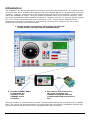
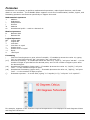
Introduction
The CUPANEL is an HMI (Human-Machine Interface) touch panel development kit. It includes an HMI
touch controller and a WYSIWYG development tool (the CUPANEL Editor) for "programming" the touch
controller. However, programming in the classical sense of the word is not required, and this is what
makes the CUPANEL so unique. Using the powerful CUPANEL Editor and a personal computer, users
can create professional human-machine interfaces by "drawing" controls (i.e. buttons, gauges, graphs,
etc…) on a canvas representing the touch controller's screen. These controls' appearance and
functionality can then be customized in great detail by selecting from a feature-rich set of menu
options that include RS-232 communication.
1. Design an HMI user interface and configure the RS-232
communication settings with the CUPANEL Editor.
2. Use the CUPANEL Editor
to download the
interface to the
CUPANEL touch
controller.
3. Execute the user interface on
the touch controller as a
standalone program that can
communicate with and control a
PLC.
Once the interface is created and the controls' communication settings are configured in the CUPANEL
Editor, the project can be downloaded to the touch panel and executed as a standalone program that
can communicate with and control a PLC (Programmable Logic Controller).
Comfile Technology Inc.
CUPANEL – User's Manual
5 of 64
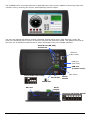
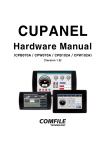
The CUPANEL touch controller features an 800x480 color touch screen capable of receiving input from
a human user by touching the screen, and displaying colorful output.
The rear and side panels feature several interfaces (RS232 Serial Ports, USB, Ethernet, Audio, SD
Card) for interfacing with a variety of electronic devices and electronic media. But please note that at
this time not all hardware features can be taken advantage of by the CUPANEL software.
Serial Ports (RS-232)
3 Channels
Ethernet
(Not used)
USB port
(Not used)
USB port
(Connect to PC)
Com1 Mode DIP switch
+ DC12-24V
(Not Used)
Power
Switch
DC12-24V
SD Card
Audio
Output
Operating Mode DIP Switch
Comfile Technology Inc.
CUPANEL – User's Manual
6 of 64
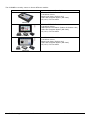
The CUPANEL currently comes in three different models:
Model
Description
-7" Color TFT LCD Touch Screen
-2.6 Million Colors
-Bezel-type Case (Indoor Use)
-2GB User Program Space (SD Card)
-CE, KCC, FCC Certified
CPB070A
-7" Color TFT LCD Touch Screen
-2.6 Million Colors
-Waterproof Front Panel (Indoor & Outdoor Use)
-2GB User Program Space (SD Card)
-CE, KCC, FCC Certified
CPW070A
-10.2" Color TFT LCD Touch Screen
-2.6 Million Colors
-Bezel-type Case (Indoor Use)
-2GB User Program Space (SD Card)
-CE, KCC, FCC Certified
CPB102A
Comfile Technology Inc.
CUPANEL – User's Manual
7 of 64
Chapter 2
Getting Started
Comfile Technology Inc.
CUPANEL – User's Manual
8 of 64
This chapter will explain how to connect the CUPANEL touch controller to a PC and PLC, install the
necessary software, and create a sample user interface.
Connecting the CUPANEL to a Personal Computer (PC)
In order to create user interfaces for the CUPANEL you will need to connect the CUPANEL to a desktop,
laptop, or other type of personal computer.
To connect a PC to the CUPANEL, Microsoft's ActiveSync (Windows XP) or Windows Mobile Device
Center (Windows Vista and Windows 7) must be installed on your PC. If your PC is running Windows
XP, follow the ActiveSync installation instructions in the Software Installation chapter. If your PC is
running Windows Vista or Windows 7, follow the Windows Mobile Device Center installation instructions
in the Software Installation chapter.
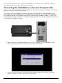
1. Once ActiveSync or Windows Mobile Device Center is installed, turn the CUPANEL on, and
connect the CUPANEL touch controller to the PC with a USB Cable.
2. Turn on the touch controller and a dialog box will appear asking you to make a language
selection. Make your choice and click the "OK" button.
Comfile Technology Inc.
CUPANEL – User's Manual
9 of 64
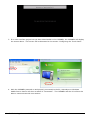
3. If no user interface project has yet been downloaded to the CUPANEL, the CUPANEL will display
the screen above. This screen will be discussed in the section "Configuring the Touch Panel".
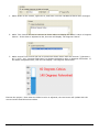
4. With the CUPANEL powered on and properly connected to the PC, ActiveSync or Windows
Mobile Device Center will show a status of "Connected". The CUPANEL and the PC will then be
able to communicate with one another.
Comfile Technology Inc.
CUPANEL – User's Manual
10 of 64
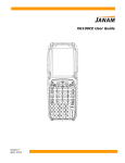
Connecting the CUPANEL to a PLC
Connecting the CUPANEL touch controller to a PC will enable the ability to create an HMI user interface
project using the CUPANEL Editor and download it to the CUPANEL touch controller, but eventually the
CUPANEL touch controller will need to be interfaced to a PLC.
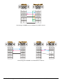
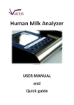
The touch controller can be connected to a PLC using any one of its three serial ports, and supports
three different communication protocols: Modbus, LS Master-K (CNET), and Mitsubishi FX. The
following diagrams illustrate the necessary connections that will need to be made for each of these
different protocols.
2 3 4 5
6 7 8 9
1 2 3 4 5
6 7 8 9
Female Type
Female Type
1
1
1
2(TXD)
2(TXD)
3(RXD)
3(RXD)
4
4
5(GND)
5(GND)
6
6
7
7
8
8
9
9
Connecting CUPANEL to Comfile Technology's TinyPLC or CUBLOC (Modbus).
Comfile Technology Inc.
CUPANEL – User's Manual
11 of 64
1
2 3 4 5
6 7 8 9
1
2 3 4 5
6 7 8 9
Female Type
Male Type
1
1
2(TXD)
2(RXD)
3(RXD)
3(TXD)
4
4
5(GND)
5(GND)
6
6
7
7
8
8
9
9
Connecting CUPANEL to an LS Master-K (CNET) device.
1
2 3 4 5
6 7 8 9
Female Type
1
2 3 4 5
6 7 8 9
Female Type
1
2 3 4 5
6 7 8 9
1
Female Type
Female Type
1
1
1
1
2(TXD)
2(RXD)
2(TXD)
2(TXD)
3(RXD)
3(TXD)
3(RXD)
3(RXD)
4
4
4
5(GND)
5(GND)
5(GND)
6
6
6
7
7
7
8
8
8
9
9
9
7(SG)
25
Connecting the CUPANEL to a Mitsubishi FX device.
Comfile Technology Inc.
CUPANEL – User's Manual
2
12 of 64
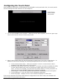
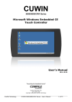
Configuring the Touch Panel
Once a physical connection is made between the CUPANEL's touch panel and a PLC, the touch panel's
RS-232 settings and other features can be configured.
Touch here 5
times to enter
setup mode.
1. Turn on the CUPANEL touch controller. When the screen above appears, touch the upper-right
corner of the screen 5 times to enter setup mode.
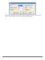
2. Once in setup mode adjust the RS-232 settings to match that of your PLC or other device. In
addition to the RS-232 settings, the following settings/features can also be configured.
a. View Communication State – Check this checkbox to show a communication status
message in the upper-left corner of the screen.
b. Enable entering setup mode while operating – If checked, this feature enables the ability
to enter setup mode at any time by touching the upper-right corner of the screen 5
times. If this is not checked, you scan still enter setup mode by touching anywhere on
the screen when the CUPANEL splash screen appears on startup.
c. Clean Project – Removes any projects that have been downloaded to the touch panel
d. Touch Calibration – Runs the touch screen calibration application.
e. Select Language – Displays of list of user interface languages to select from.
If the correct physical connections and software configurations have been made, the CUPANEL will
then be able to communicate with a PLC.
Comfile Technology Inc.
CUPANEL – User's Manual
13 of 64
Creating a User Interface
The previous sections explained how to connect the CUPANEL touch controller to a PC and a PLC. This
section will explain how to create a very simple HMI user interface, download it to the CUPANEL touch
controller, and execute it as a standalone program that communicates with the PLC. This
demonstration will use the CUBLOC CB280 and the CUBLOC study board as the PLC.
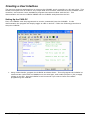
Setting Up the CUBLOC
First, the CUBLOC must be programmed to receive commands from the CUPANEL. In this
demonstration the program will simply toggle an LED on and off. Follow the following procedure to
setup the CUBLOC.
1. Using Cubloc Studio, program the CUBLOC as shown above. This will program the CUBLOC to
communicate via RS-232 and Modbus over its serial port, and enable I/O port 0 (P0) to apply
voltage to an LED. See the CUBLOC's user's manual if you wish to learn more about
programming the CUBLOC.
Comfile Technology Inc.
CUPANEL – User's Manual
14 of 64
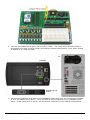
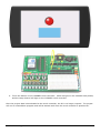
2. Connect the CUBLOC's I/O port 0 (P0) to LED 0 (LED0). The image above illustrates how to
accomplish this using a yellow jumper wire and the CUBLOC Study Board. Then, when voltage
is applied to P0, LED0 will light.
PC
CUPANEL
CUBLOC Study
Board
3. Connect the CUBLOC's serial port to the CUPANEL's COM1 serial port and connect the CUPANEL
to a PC via USB as shown above. There will now be two connections to the CUPANEL's touch
panel: a USB connection to the PC, and an RS-232 connection to the CUBLOC Study Board.
Comfile Technology Inc.
CUPANEL – User's Manual
15 of 64
Designing and Configuring the HMI User Interface with the CUPANEL Editor
With the CUPANEL properly connected to a PC and the CUBLOC study board, a user interface project
can be created with the CUPANEL Editor. Follow CUPANEL Editor installation instructions in the
Software Installation chapter to download and install the CUPANEL Editor.
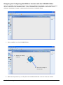
1. Once installed, run the CUPANEL Editor.
1. Select the Lamp
Control
2. Draw the Lamp on
the screen
2. Select a Lamp Control (i.e. LED) from the toolbar and draw it on the center of screen.
Comfile Technology Inc.
CUPANEL – User's Manual
16 of 64
1. Select the Button
Control
2. Draw the Button on
the screen
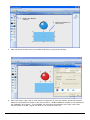
3. Select a Button Control from the toolbar and draw it just below the lamp
4. Select the lamp, right-click it, and choose "Properties" to open the Lamp's properties window.
Adjust the properties as shown in the screen above. Modbus Address 0x0000 is the address of
the CUBLOC's P0 I/O port. The CUPANEL will read from this address and "light" this Lamp
Control when P0 is ON. Adjust the Hue to 0 to make the LED red.
Comfile Technology Inc.
CUPANEL – User's Manual
17 of 64
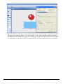
5. Select the Button, right-click it, and choose properties to open the button's properties window.
Adjust the properties as shown in the screen above. Once again, Modbus Address 0x0000 is
the address of the CUBLOC's P0 I/O port. Setting the "Action to perform when pressed" option
to "Toggle Bit" will cause P0's state to toggle between on and off when the button is pressed.
Comfile Technology Inc.
CUPANEL – User's Manual
18 of 64
Downloading and Running the HMI User Interface on the Touch Controller
Now that the HMI user interface has been designed and configured with the CUPANEL Editor, it can be
downloaded and executed on the CUPANEL touch controller.
IMPORTANT: When a project is downloaded to the CUPANEL, it is downloaded to the touch
controller's SD Card. Ensure an SD card is plugged into the touch controller before downloading.
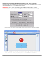
1. Adjust the RS-232 settings on the CUPANEL touch controller to match that of the CUBLOC.
2. With the CUPANEL touch controller connected to the PC via USB, download the project to the
touch controller by clicking the lightning bolt icon in the CUPANEL Editor's toolbar.
Comfile Technology Inc.
CUPANEL – User's Manual
19 of 64
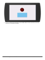
3. The user interface that was drawn in the CUPANEL Editor will then execute on the touch
controller as a standalone program.
Comfile Technology Inc.
CUPANEL – User's Manual
20 of 64
4. Touch the button on the CUPANEL touch controller. LED0 will light on the CUBLOC study board,
and the Lamp Control will light on the CUPANEL touch controller.
Once the project data is downloaded to the touch controller, the PC is no longer required. The project
will run as a standalone program and will be started each time the touch controller is powered on.
Comfile Technology Inc.
CUPANEL – User's Manual
21 of 64
Chapter 3
The CUPANEL
Editor
Comfile Technology Inc.
CUPANEL – User's Manual
22 of 64
The Main Window
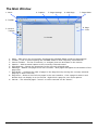
1. Menu
4. Caption
5. Page Settings
6. Add Page
7. Page Order
2. Toolbar
8. Page
View
3. Control
Toolbox
9. Canvas
1.
2.
3.
4.
5.
6.
Menu – Main menu for conveniently accessing the CUPANEL Editor's features and settings.
Toolbar – A set of icons exposing the CUPANEL Editor's most frequently used features.
Control Toolbox – The list of controls (i.e. widgets) that can be drawn on the canvas.
Caption – Adds a textual caption to the currently selected control.
Page Settings – Opens the properties for the currently selected page.
Add Page – Adds a new page to the user interface. New pages will appear at the bottom of the
page view.
7. Page Order – Changes the order of pages in the Page View by moving the currently selected
page up or down in the list.
8. Page View – Shows a list of all the pages in the user interface. Click a page to select it and
double-click it to display it on the canvas. Right-Click a page for even more options.
9. Canvas – The selected page's "screen" on which controls can be "drawn".
Comfile Technology Inc.
CUPANEL – User's Manual
23 of 64
Menus
File Menu
New Project
Open Project
Save
Save As…
1–4
Exit
Edit Menu
Undo
Redo
Cut
Copy
Paste
Project Menu
Creates a new CUPANEL project with an
empty canvas.
Opens an existing project from an
existing CUPANEL project file (*.cnp)
Saves the current project. If the
project has never been saved, it will
prompt for a file name.
Saves the current project under a new
file name.
4 most recently opened project files
Closes the CUPANEL Editor
Undoes the last edit operation
Redoes and last edit operating that was
undone.
Removes the currently selected
items(s) and saves them to the
clipboard.
Saves the currently selected items(s)
to the clipboard without removing
them.
Pastes a copy of the latest item(s)
saved to the clipboard
Preview
(Simulator)
Download Project
Data to CuPanel
Page Settings
Project Settings
Tools Menu
Editor Options
Firmware Update
Comfile Technology Inc.
CUPANEL – User's Manual
Runs the current project on the
PC as if it were running on the
CUPANEL touch controller.
Downloads the project to the
CUPANEL touch controller.
Opens the current page's settings
for editing.
Opens the current project's
settings for editing.
Opens the CUPANEL Editor's
settings for editing.
Updates the CUPANEL touch
controller's firmware.
24 of 64
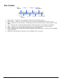
The Toolbar
1. New
Project
3. Save
2. Open
Project
5. Copy
4. Cut
7. Preview
(Simulator)
6. Paste
8. Download
1. New Project – Creates a new CUPANEL project with and empty canvas.
2. Open Project – Opens an existing project from an existing CUPANEL project file (*.cnp)
3. Save – Saves the current project. If the project has never been saved, it will prompt for a file
name.
4. Cut – Removes the currently selected item(s) and saves them on the system's clipboard.
5. Copy – Saves the currently selected items(s) to the clipboard without removing them.
6. Paste – Pastes a copy of the latest item(s) saved to the clipboard.
7. Preview (Simulator) – Runs the current project on the PC as if it were running on the CUPANEL
touch controller.
8. Download - Downloads the project to the CUPANEL touch controller.
Comfile Technology Inc.
CUPANEL – User's Manual
25 of 64
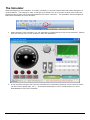
The Simulator
When developing a user interface, it is often necessary to test its functionality and make changes in a
cyclical fashion. This change Æ test Æ change cycle would incur a lot of time if each time a test was
performed the project had to be downloaded to the touch controller. The Simulator was developed to
make this procedure far more efficient.
1. When testing a user interface, it is not necessary to download it to the touch controller. Rather,
click the Preview icon in the Toolbar to start the Simulator.
2. A new window will open with the user interface fully interactive (Buttons can be clicked, knobs
can be turned, lamps light, etc…). It behaves identically to how it would behave if it were
downloaded to the touch controller.
Comfile Technology Inc.
CUPANEL – User's Manual
26 of 64
3. Using the PC's serial ports, the Simulator can also communicate with a PLC or other electronic
device. Click the "Options" button to open the RS-232 settings dialog.
Comfile Technology Inc.
CUPANEL – User's Manual
27 of 64
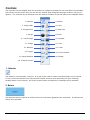
Controls
The Controls are the widgets that can be drawn on a page to provide the user interface's functionality.
Once drawn on the screen they can be moved, resized, and configured through a feature-rich set of
options. The controls can be selected from the Control Toolbox on the left side of the CUPANEL Editor.
1. Selector
3. Lamp (LED)
5. Progress Bar
7. Gauge
9. Trend Graph
11. Image
13. Watcher
15. Logger
17. Popup Window
2. Button
4. Lever
6. Slider Bar
8. Knob
10. Keypad
12. Text
14. Timer
16. Event Handler
18. Binder
19. Custom Control
1. Selector
The Selector is not actually a control. It is just a tool used to select controls already on the canvas.
To use, select the Selector from the Control Toolbox and then click and drag over any control(s)
already drawn on the canvas. All of the controls within the Selector's rectangle will be selected.
2. Button
The Button Control is similar to buttons found in most other graphical user interfaces. It performs an
action when pressed.
Comfile Technology Inc.
CUPANEL – User's Manual
28 of 64
3. Lamp (LED)
The Lamp Control is analogous to a lamp or LED(Light Emitting Diode) indicator that one might see on
a machine or an appliance. Is shows lit when on, and unlit when off.
4. The Lever
The Lever Control is analogous to a typical toggle switch with an "on" and "off " state.
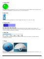
5. Progress Bar
The Progress Bar Control is similar to progress bars found in other graphical user interfaces. It
displays a progress meter showing how much of a task is completed and how much of a task remains.
It can be oriented horizontally or vertically.
6. Slider Bar
The Slider Bar Control allows the user to adjust a value within a finite range. It can be oriented
horizontally or vertically.
7. Gauge
The Gauge control is analogous to the gauges commonly found on instrument panels everywhere. It is
an output-only control with a rich set of aesthetic customizations.
Comfile Technology Inc.
CUPANEL – User's Manual
29 of 64
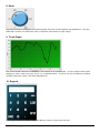
8. Knob
The Knob Control is analogous to knobs typically found on control panels and appliances. Like the
Slider Bar Control it is allows the user to adjust a value within a finite range.
9. Trend Graph
The Trend Graph Control is analogous to the screen on an oscilloscope. It is an output control that
displays a value, read over time, on an x-y coordinate plane. It has a rich set of features including
multiple channels, colors, and scale adjustments
10. Keypad
The Keypad Control is used to accept arbitrary numeric input from the user.
Comfile Technology Inc.
CUPANEL – User's Manual
30 of 64
11. Image
The Image Control is a purely aesthetic control. It is used to add logos, backgrounds, photographs or
any other graphic to the canvas to visually enhance the user interface.
12. Text
The Text Control is used to add messages, labels, or any other text to the user interface. It has a rich
set of customizations that include font, size, color, and alignment.
13. Watcher
The Watcher Control is used to continuously read from a PLC or other electronic device, monitoring the
device's state, and updating the user interface accordingly. It accomplishes this by setting variables
based on values read from the PLC. It is functional only, and is therefore not displayed on the user
interface at runtime.
14. Timer
The Timer Control is used to create periodic events (e.g. an event every n seconds). Using the Event
Handler Control, actions can be attached to these events so they are performed whenever the Timer
ticks (i.e. Timer's interval elapses). A common scenario is writing to a PLC every n seconds; the Timer
would be used to define the time interval, n, and the Event Handler would be used to define the action
of writing to the PLC when the time interval elapses. The Timer Control is functional only, and is
therefore not displayed on the user interface at runtime
Comfile Technology Inc.
CUPANEL – User's Manual
31 of 64
15. Logger
The Logger Control keeps a running log of notable events that may occur while a system is running.
Use with the Event Handler Control to specify when and what to log.
16. Event Handler
The Event Handler Control is a powerful control used to define actions to perform when a certain event
occurs. Actions can be setting values, writing to a PLC, navigating to a new page, etc… just to name a
few. Events can be a Timer tick, a Page load, a button click, etc… An action defines what should be
performed, and an event defines when and/or on what condition the action should be performed. The
Event Handler Control is functional only, and is therefore not displayed on the user interface at
runtime.
17. Popup Window
The Popup Window Control is used to define a popup window to display under a certain condition. The
condition is configured in the Popup Window Control's properties, but the actual content of the popup
window is created as a Page. Drawing a Popup Window Control on the canvas defines size of the
popup window and location where the popup window will display.
"I'm a popup window!" textbox.
"OK" button
"Cancel" button
When drawing a Popup Window Control on the canvas, the controls in the in the Page to be displayed
will show as green dotted lines. It may be necessary to reposition the controls on the Page to ensure
they fit within the popup window.
Comfile Technology Inc.
CUPANEL – User's Manual
32 of 64
18. Binder
The Binder Control was created strictly for performance and efficiency reasons. It performs I/O read
operations on behalf of multiple controls thereby reducing redundancy and improving I/O performance.
It is functional only, and is therefore not displayed on the user interface at runtime
19. Custom Control
The Custom Control was created to provide a way to extend the CUPANEL Editor with custom
functionality. If you are interested in this feature, please contact Comfile Technology.
Comfile Technology Inc.
CUPANEL – User's Manual
33 of 64
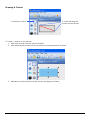
Drawing A Control
1. Select the control
2. Click and drag the
control on the canvas.
To "draw" a control on the canvas:
1. Select the control from the Control Toolbox
2. Click and drag the control on the canvas to the desired position and size.
3. Release the mouse button and the control will appear as drawn.
Comfile Technology Inc.
CUPANEL – User's Manual
34 of 64
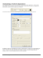
Customizing a Control's Appearance
The CUPANEL Editor has a rich set of features for customizing controls' appearance. These include
fonts, shapes, colors, gradients, and even custom images. Each control is unique in its appearance
and features, so each control's properties are different.
Controls that feature text of any kind will typically have properties for font, style, and color.
In addition a caption can be added to any control. Captions feature a richer set of customizations that
include font, style, color, size, alignment, positioning, and more. For multiline text, type a carriage
return. The text can be static text that never changes, or dynamic text that changes based on
variables' values. See the Variables section for more information.
Comfile Technology Inc.
CUPANEL – User's Manual
35 of 64
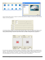
Some controls feature built-in images or presets that provide the ability to choose from a list of styles,
shapes, and color gradients.
Controls that feature graphics of some kind will typically feature some color adjustment features such
as hue and saturation those controls that feature built-in images (raster graphics) or the standard
red(R)-green(G)-blue(B) values for those controls that are drawn as shapes (vector graphics).
For those user interfaces that require complete customization, custom images can be assigned to the
controls. The image above shows a button being customized to display a power symbol, and to show
differently when it's pressed or released. The images can be further customized by adjusting their
luminance/brightness, and can even treat black or white pixels as transparent.
Comfile Technology Inc.
CUPANEL – User's Manual
36 of 64
Finally there are controls like the Knob, Slider, Gauge and Trend Graph that show scales. These scales
can be customized to specify the number of divisions, subdivisions, range of values, and even where or
how the scale is drawn.
Comfile Technology Inc.
CUPANEL – User's Manual
37 of 64
Variables
One of the most fundamental concepts in using the CUPANEL Editor is making use of variables. A
variable is just a named value that can be referred to by any control or page. A variable can be read
from in order to use the variable's value for some purpose, or written to in order to change or update
the variable's value.
A variable can be defined in the properties of any control that can read from or write to a variable as
shown in the image above. The "$" textbox is the variable's name; in this case "Amplitude". The
"Initial Value" is the variable's starting value. The "Save to File" option is used to store the value to a
file any time it is changed so it can be restored should the program be closed and restarted again.
Once a variable is defined, it can be used anywhere in the user interface.
For example, suppose we wanted to adjust a variable's value with a Slider, and display the value on a
Trend Graph.
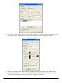
1. Right-Click the Slider Control to open its properties. Give the variable a name of "Amplitude"
and an initial value of "0". Now, when the Slider is adjusted, the Slider's value will be written
to the variable "Amplitude".
Comfile Technology Inc.
CUPANEL – User's Manual
38 of 64
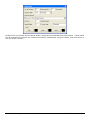
2. To have the Trend Graph read from the variable "Amplitude", right-click the Trend Graph, select
the channel in the "Channels List", and click the "Modify" button to change its settings.
3. Check the "Compute value from formula" checkbox and type the name of the variable in the
textbox prefixed with a "$". The "$" prefix distinguishes variables from other text. Now the
Trend Graph will always display the value of the variable "Amplitude".
Comfile Technology Inc.
CUPANEL – User's Manual
39 of 64
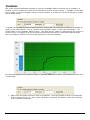
Execute the project. When the Slider's value is adjusted, the Trend Graph will reflect that adjustment.
System Variables
The CUPANEL runtime predefines the following system variables.
Name
$sys_year
$sys_month
$sys_day
$sys_hour
$sys_minute
$sys_second
$sys_tick_count
$sys_untreated_packet_count
Comfile Technology Inc.
The
The
The
The
The
The
The
The
Value
current year
current month
current day
current hour (0 – 23)
current minute
current second
number of milliseconds since the system booted
number of packets waiting to be sent
CUPANEL – User's Manual
40 of 64
Formulas
Sometimes it is necessary to perform mathematical operations, make logical decisions, and format
data in a user interface. The CUPANEL Editor supports a rich set of mathematical, bitwise, logical, and
formatting operators and features specifically to support this need.
Mathematical Operators
+
Addition
Subtraction
*
Multiplication
/
Division
%
Modulus
0x
Hexadecimal prefix – 0x0A is a decimal 10.
Bitwise Operators
&
Boolean AND
|
Boolean OR
Logical Operators
&&
Logical AND
||
Logical OR
<
Less than
<=
Less than or equal
>
Greater than
>=
Greater than or equal
==
Equal
!=
Not Equal
Formatting
;
Tells the formula parser to print value of variable – If variable $a stores the value 10, typing
"$a" in a text field will print "$a", but typing "$a;" will print "10".
(d.f) Decimal Formatting – If variable $a stores the value 9.4, "$a(2.3);" will print "09.400". d is the
number of digits to print before the decimal point, and f is the number of digits to print after
the decimal point.
(nh) Hexadecimal Formatting (lower case) – If variable $a stores the value 10, "$a(3h);" will print
"00a". n is the number of digits to print.
(nH) Hexadecimal Formatting (upper case) – If variable $a stores the value 10, "$a(3H);" will print
"00A". n is the number of digits to print.
{}
Evaluation operator – In a text field, typing "1+2 equals {1+2};" will print "1+2 equals 3".
For example, suppose a user interface required temperatures to be displayed in both Degrees Celsius
and Degrees Fahrenheit:
Comfile Technology Inc.
CUPANEL – User's Manual
41 of 64
1. Add a Slider to the canvas, right-click it, and have it set the variable $Celsius when changed.
2. Add a Text Control and set its content as shown above to display the Slider's value in Degrees
Celsius. If the slider is adjusted to 60, this text will display "60 Degrees Celsius".
3. Add a second Text Control and set its content as shown above with the formula "{($Celsius +
40) * (9/5) - 40}; Degrees Fahrenheit" to display the Slider's value in Degrees Fahrenheit. If
the slider is adjusted to 60, this text will display "140 Degrees Fahrenheit".
Execute the project. Now when the Slider's value is adjusted, the text boxes will update with the
correct Celsius and Fahrenheit values
Comfile Technology Inc.
CUPANEL – User's Manual
42 of 64
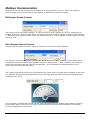
Modbus Communication
Most of the controls can be bound to a specific bit or word register on a PLC. When the register's
value changes, any control bound to that register is updated to reflect the change.
Bit Register Bound Controls
The Lamp Control is a simple example. It can be bound to a bit register on a PLC by configuring its
Modbus properties. In the image above, the Lamp Control is bound to register 0x1000 on slave device
1. Whenever this register's value is ON, the lamp will show lit. If this register's value is OFF, the lamp
will show unlit.
Word Register Bound Controls
Controls with the ability to show a range of values can be bound to word registers.
The Gauge is a good example of a control that can be bound to a word register. In the image above,
the Gauge control is bound to word register 0x7000 on slave device 1. But in addition, the range of
valid values read from the PLC can also be specified. In this example the Gauge expects to only
receive values from 0 through 1024.
The values read from the PLC may not always be the values that one would want to display to the user.
For example, the gauge might read values from 0 through 1024, but these numbers might represent
voltages from 0 to 12.
For this reason, word-bound controls can be scaled by specifying the "Display Value Range" property.
In the image above, the values 0 through 1024 as read from the PLC will be scaled to 0.0 through
12.0 when displayed on the screen.
Comfile Technology Inc.
CUPANEL – User's Manual
43 of 64
Two-Way Binding
Those controls that can receive input from the user (Button, Slider, Knob, etc…) can also be bound to
PLC registers. In these cases, when the user adjusts the control, a value is written to the PLC. But
this binding is two-way, so, if the register's value is updated by some other means besides the bound
control, the bound control will read register's value and update accordingly.
When many controls are bound to the PLC, the communication channel can become congested.
For example, if there are 8 Lamp Controls bound to bit registers 0x0000 through 0x0007, 8 separate
read operations will be issued.
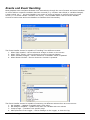
Using the Binder Control to Reduce Congestion
The Binder Control was created to alleviate some of this congestion. Using the Binder Control several
registers can be read simultaneously in one read operation by specifying a range of registers to read.
In the example above, bit registers 0x0000 through 0x0007 will be read simultaneously in one read
operation, alleviating the system of the 8 individual read operations that would occur without the
binder.
Comfile Technology Inc.
CUPANEL – User's Manual
44 of 64
Events and Event Handling
Most graphical user interfaces facilitate their interactivity through the use of events and event handlers.
An event defines a specific condition that has occurred (e.g. a button was clicked, a variable changed,
a timer ticked, etc…). An event handler is an action or series of actions to perform when the event
occurs (i.e. an event handler "handles" the event). The CUPANEL Editor uses the Event Handler
Control to bind events and event handlers to facilitate this functionality.
The Event Handler Control is capable of "handling" four different events:
1. When Page Loaded – Occurs whenever a Page is shown on the screen.
2. When Timer Ticked – Occurs whenever a timer's interval elapses.
3. When Variable Changed – Occurs whenever a variable's value is updated.
4. When Button Clicked – Occurs whenever a button is pressed.
The Event Handler Control is capable of executing 10 different actions when an event occurs:
1. Set Variable – Updates a variable with a new value.
2. Set Multiple Variables – Update more than one variable with new values
3. Jump to Page – Transition to a specific page
4. Add to/Remove from Logger – Add a message to the Logger, or clear the log.
Comfile Technology Inc.
CUPANEL – User's Manual
45 of 64
5. Add to File – Append data to a specified file.
6. Start Timer – Make a timer begin counting
7. Stop Timer – Make a timer stop counting
8. Write to PLC – Write to a specific register on a PLC
9. Access Trend Graph – Starts or stops a Trend Graph.
10. Change Text – Updates a control's text.
Each action has its own unique set of options, as each action is unique in its functionality.
The Event Handler Control can also place a condition and a repeat limitation on the action. The
condition can be a formula restricting when the action can be executed. The repeat limitation specifies
how often an action can be performed.
Comfile Technology Inc.
CUPANEL – User's Manual
46 of 64
Software
Installation
Comfile Technology Inc.
CUPANEL – User's Manual
47 of 64
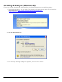
Installing ActiveSync (Windows XP)
If you are running Windows XP, please perform the following procedure to install ActiveSync.
1. Download ActiveSync – At the time of this writing, the latest version was 4.5 and could be
downloaded from http://www.microsoft.com/windowsmobile/enus/downloads/microsoft/activesync-download.mspx.
2. Run the downloaded file.
3. If a “Security Warning” dialog box appears, click the “Run” button.
Comfile Technology Inc.
CUPANEL – User's Manual
48 of 64
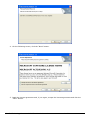
4. On the following screen, click the “Next” button.
5. Read the license agreement and, if you agree, accept the license agreement and click the
“Next” button.
Comfile Technology Inc.
CUPANEL – User's Manual
49 of 64
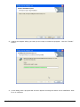
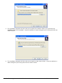
6. On the “Customer Information” dialog, enter the appropriate information in the “User Name”
and “Organization” text boxes. Then click the “Next” button.
7. On the “Destination Folder” dialog, accept the default or change the destination folder. Then
click the “Next” button.
Comfile Technology Inc.
CUPANEL – User's Manual
50 of 64
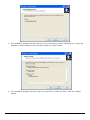
8. A dialog will appear telling you that you are ready to install the program. Click the “Install”
button.
9. A new dialog with a progress bar will then appear showing the status of the installation. Wait
for it to complete.
Comfile Technology Inc.
CUPANEL – User's Manual
51 of 64
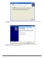
10. When installation is complete, a dialog will appear saying “Microsoft ActivSync 4.5 Setup is
complete”. Click the “Finish” button.
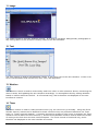
11. ActiveSync is now installed, and you should see the ActiveSync icon in your system tray. If
you double-click the system tray icon, the ActiveSync window will display showing a status of
“Not Connected.”
Comfile Technology Inc.
CUPANEL – User's Manual
52 of 64
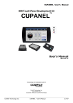
12. Using a USB cable, connect the CUPANEL to the PC. You will probably hear a few sounds
from the PC and the CUPANEL as the connection is established.
13. ActiveSync will then prompt you to create a partnership between the PC and the CUPANEL.
Make your selection. If you're not sure, just choose “No”. Then click the “Next” button.
Comfile Technology Inc.
CUPANEL – User's Manual
53 of 64
14. ActiveSync will then show a status of “Connected”, and the ActiveSync system tray icon will
change indicating the CUPANEL is connected to the PC. Click the “Explore” icon.
Comfile Technology Inc.
CUPANEL – User's Manual
54 of 64
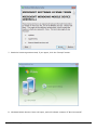
Installing Windows Mobile Device Center (Windows Vista, 7)
If you are running Windows Vista or Windows 7, please perform the following procedure to install
Windows Mobile Device Center.
1. Download Windows Mobile Device Center. At the time of this writing, the latest version was 6.1
and could be downloaded from
http://www.microsoft.com/downloads/details.aspx?FamilyId=46F72DF1-E46A-4A5F-A79109F07AAA1914&displaylang=en
2. Run the downloaded file.
3. If you are presented with a “User Account Control” dialog, click the “Yes” button.
Comfile Technology Inc.
CUPANEL – User's Manual
55 of 64
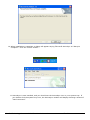
4. Windows Mobile Device Center will begin installing. Wait for it to finish.
5. When the installation is finished, a message will appear in the system tray telling you that the
installation was successful.
6. Run “Windows Media Device Center” from the Windows Start Menu.
Comfile Technology Inc.
CUPANEL – User's Manual
56 of 64
7. Read the license agreement and, if you agree, click the “Accept” button.
8. Windows Mobile Device Center will open, and will indicate a status of “Not Connected”.
Comfile Technology Inc.
CUPANEL – User's Manual
57 of 64
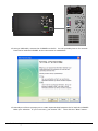
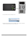
9. Using a USB cable, connect the CUPANEL to the PC.
10. Windows will begin installing a driver for the CUPANEL. When it is finished, a message will
display in the system tray saying “Your device is ready to use.”
Comfile Technology Inc.
CUPANEL – User's Manual
58 of 64
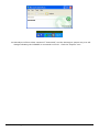
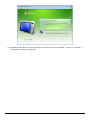
11. Windows Mobile Device Center will begin connecting with the CUPANEL. When it is finished, it
will display a status of connected.
Comfile Technology Inc.
CUPANEL – User's Manual
59 of 64
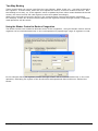
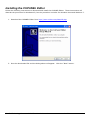
Installing the CUPANEL Editor
Follow the following instructions to download and install the CUPANEL Editor. These instructions will
describe the procedure for Windows XP, but the procedure is similar for Windows Vista and Windows 7.
1. Download the CUPANEL Editor from http://www.cubloc.com/data/08.php.
2. Run the downloaded file and the dialog above will appear. Click the "Next" button.
Comfile Technology Inc.
CUPANEL – User's Manual
60 of 64
3. The installation program will then ask you to specify the location where you would like the
CUPANEL Editor to be installed. Keep the defaults or make changes to your liking and click the
"Next" button.
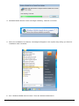
4. The installation program will then ask you to specify a Start Menu folder. Keep the defaults or
make changes to your liking and click the "Next" button.
Comfile Technology Inc.
CUPANEL – User's Manual
61 of 64
5. The installation program will then ask you if you would like to create a desktop icon. Keep the
defaults or make changes to your liking and click the "Next" button.
6. The installation program will then inform you that all it is ready to install. Click the "Install"
button.
Comfile Technology Inc.
CUPANEL – User's Manual
62 of 64
7. The installation program will then begin copying the necessary files to your computer. Wait for
it to finish.
8. When the installation is finished, the following screen will appear. You can now run the
CUPANEL editor. Click the "Finish" button.
Comfile Technology Inc.
CUPANEL – User's Manual
63 of 64
9. When the CUPANEL Editor is run, the CUPANEL Editor's main window will appear.
Comfile Technology Inc.
CUPANEL – User's Manual
64 of 64