1
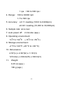
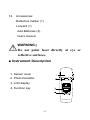
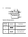
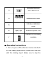
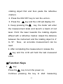
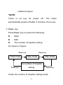
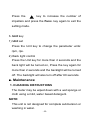
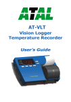
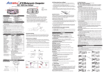
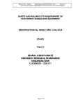
99 Washington Street
Melrose, MA 02176
Phone 781-665-1400
Toll Free 1-800-517-8431
Visit us at www.TestEquipmentDepot.com
EM30
TACHOMETER
1
User Manual
■. Introduction
Thank you for purchasing this tachometer from
SUPCO. Please take a few minutes to browse through
this user manual before you begin to operate the meter
to ensure that you are fully familiarized with how best
to operate the meter as accurately and safely as
possible.
The meter is a rotational speed (measured in rpm)
measuring instrument. It is normally used to measure
rotational speed, e.g. of fan blades, impellers, drums
and spindles.
Warning! Keep a safe distance from the
rotating object being measured.
1.1 Precautions safety measures
To get the best service from this meter, please read
this user's manual carefully and observe the detailed
safety precautions strictly.
1.1.1 During use
-1-
1. For reliable measurements it is necessary to use
reflective markers. To apply the reflective markers,
wait until the object to be measured has come to a
standstill.
2. The ideal distance to the measurement object is
between 4” to 16”. During the measurement, always
aim at the reflective marker from an angle of
approximately 30°. This avoids multiple reflections
from the surface.
3. If no reflective marker can be attached, it must be
checked whether the reflective properties of a
reflective point on the measurement object are
sufficient for rpm measurement. In this case, aim at
the measurement object from the vertical, and check
whether a value is displayed. If the measurement
object displays several reflections per revolution, the
number of ventilator vanes must be set (e.g.
reflective ventilator with 5 vanes) in order to obtain
correct rpm measurements.
-2-
4. If the OL symbol is displayed on the LCD, it means
the readings are outside the measuring range.
Please keep within the specified measuring range.
5. Never store the product together with solvents, acids
or other aggressive substances.
1.1.2 Maintaining the product
l
Do not measure at a high temperature, high
humidity locations.
l
When not using the instrument for a long time,
please remove the battery and avoid storing in
high temperature and high humidity.
■ Features
1. Display: 6 digits LCD Display
2. Parameters: rpm, rps
3. Resolution: 0.1 rpm(100 to 999.9 rpm)
0.1 rps(1.7 to 100 rps)
1 rpm(1000 to 30000 rpm)
-3-
1 rps(100 to 500 rps)
4. Range: 100 to 30000 rpm
1.7 to 500 rps
5. Accuracy: ±0.1%reading (100.0 to 9,999rpm)
±0.02%reading (10,000 to 30,000rpm)
6. Sample rate: once /sec
7. Auto power off:
2 minutes (app.)
8. Operating environment:
14oF to 122oF; (-10oC to +50oC)
9. Storage environment:
-4 oF to 140 oF (-20 oC to +60 oC)
10. Dimensions:
4.76”(L) x 2.36”(W) x 1.18”(H)
121mm(L) x 60mm(W) x 30mm(H)
11. Weight:
6.35 oz (app.)
180 g (app.)
-4-
12. Accessories:
Reflective marker (1)
Lanyard (1)
AAA Batteries (3).
Users manual
WARNING!
Do not point laser directly at eye or
reflective surfaces.
■ Instrument Description
1. Sensor cover
2. Photo transistor
3. LCD display
4. Function key
Unit
Func .
Rotate speed meter
-5-
l
LCD Display
Symbol Designations
Number
of Order
Symbol
Functions
Indicates Data Hold
1
Indicates Maximum
2
Value Measured.
-6-
Indicating Minimum
3
Value Measured
4
Measurement Value
Indicates calibration
5
6
mode
rpm、rps
Rotational speed units
Indicates a Low battery
condition
7
■ Operating Instructions
1. Cut out a piece of the reflective marker and attach
it to the rotating object which is under test. And then
start this rotating object. (Make sure to stop the
-7-
rotating object first and then paste the reflective
marker)
2. Press the ON/ OFF key to turn the unit on.
3. Press the
key and the LCD will display 0.0.
4. Keep pressing the
key, the meter will enter
the measurement state and launch a beam of red
laser. Point the laser towards the rotating objects
affixed with a reflective marker. Adjust the distance
between the instrument and the rotating object to 4”
to 16”.
Now,
an accurate measurement can be
read.
4. After completing the measurement, release the
key and the LCD will hold the last measured
value.
■Function Keys
1.
key
Press the
key to turn the power on.
Continue pressing the key to start measuring
-8-
rotational speed.
*NOTE:
There is no key for power off. The meter
automatically powers off after 2 minutes of non-use.
2. Func. key
Press Func. key to select the following:
l
MAX
l
MIN
l
The number of impeller setting
As shown in Figure:
Func.key
Hold mode
Func.key
Max mode
Min mode
The number of impeller
Func.key
setting
Func.key
Under the number of impeller setting mode:
-9-
Press the
key to increase the number of
impellers and press the Func. key again to exit the
setting mode.
3. Unit key
1) Unit set
Press the Unit key to change the parameter units:
rpm, rps.
2) Back light control
Press the Unit key for more than 2 seconds and the
back light will be turned on, Press the key again for
more than 2 seconds and the backlight will be turned
off. The backlight will also turn off after 60 seconds.
■. Maintenance
1. CLEANING INSTRUCTIONS
The meter may be wiped down with a wet sponge or
cloth using a mild, water based detergent.
NOTE:
This unit is not designed for complete submersion or
washing in water.
-10-
2. BATTERY REPLACEMENT
Use the following procedure:
When the battery voltage drops below proper
operation range the
symbol will appear on the
LCD display and the battery needs to be replaced.
∞ Press the battery cover towards the arrowhead to
open the battery cover.
∞ Replace the battery with three new AAA (1.5V)
batteries.
∞ Replace the battery cover.
WARRANTY
Sealed Unit Parts Co., Inc. warrants that it will repair or
furnish without charge a similar product to replace any
product which, within the specified warranty term after
the date of sale by the Wholesaler, is proved to the
satisfaction of Sealed Unit Parts Co., Inc. , to have
-11-
been defective at the time it was sold. Said warranty is
in effect only when said item is used in accordance
with the instructions and recommendations of Sealed
Unit Parts Co., Inc.
This warranty applies only to products which after
shipment from the factory, have not been altered,
changed,
repaired,
or
treated
in
any
manner
whatsoever.
This warranty to repair or replace is the only warranty
either expressed, implied or statutory and is the only
warranty being issued herein; Sealed Unit Parts Co.,
Inc.'s liability in connection with its products is
expressly limited to the repair or replacement of
defective parts. All other damages and warranties,
statutory or otherwise, are being expressly excluded.
-12-
No representative of Sealed Unit Parts Co., Inc. has
authority to change this warranty in any manner
whatsoever. No attempt to repair or promise to repair
or improve any part covered by this warranty by any
representative of this company shall be effective
unless signed by a properly authorized officer of
WLS2108
Sealed Unit Parts Co., Inc.
-13Test Equipment Depot - 800.517.8431 - 99 Washington Street Melrose, MA 02176
TestEquipmentDepot.com