1
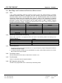
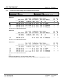
FCC TEST REPORT
Report No. : FR182617
FCC RADIO TEST REPORT
according to
47 CFR FCC Part 15 Subpart C § 15.247
Equipment
Brand Name
Model No.
Filing Type
Applicant
FCC ID
Manufacturer
:
:
:
:
:
Lytro Light Field Camera
Lytro
A1
New Application
Lytro, Inc.
200 W. Evelyn Ave., Suite 120 Mountain View,
CA 94041 USA
: ZMQA1
: Chicony Electronics Co., Ltd
No.25, Wugong 6th Rd., Wugu Dist.,
New Taipei City 248, Taiwan (R.O.C.)
: Aug. 24, 2011
Final Test Date : Sep. 06, 2011
Received Date
Statement
Test result included is only for the 802.11b/g/n part of the product.
The test result in this report refers exclusively to the presented test model / sample.
Without written approval of SPORTON International Inc., the test report shall not be reproduced except in full.
The measurements and test results shown in this test report were made in accordance with the procedures and
found in compliance with the limit given in ANSI C63.4-2003 and 47 CFR FCC Part 15 Subpart C.
The test equipment used to perform the test is calibrated and traceable to NML/ROC.
SPORTON International Inc.
No. 52 Hwa Ya 1st Rd., Hwa Ya Technology Park, Kwei-Shan Hsiang, Tao Yuan Hsien, Taiwan, R.O.C.
SPORTON International Inc.
Report Format Version: a
FCC TEST REPORT
Report No. : FR182617
Table of Contents
1 SUMMARY OF THE TEST RESULT .......................................................................................................................2
2 GENERAL INFORMATION......................................................................................................................................3
2.1
Product Details .........................................................................................................................................................................................3
2.2
Accessories ..............................................................................................................................................................................................3
2.3
Table for Filed Antenna ............................................................................................................................................................................3
2.4
Table for Carrier Frequencies ..................................................................................................................................................................4
2.5
Table for Test Modes ...............................................................................................................................................................................4
2.6
Table for Testing Locations ......................................................................................................................................................................4
2.7
Table for Supporting Units .......................................................................................................................................................................4
2.8
Table for Parameters of Test Software Setting ........................................................................................................................................5
2.9
EUT Operation during Test ......................................................................................................................................................................5
2.10
Test Configuration ....................................................................................................................................................................................6
3 TEST RESULT .........................................................................................................................................................8
3.1
AC Power Line Conducted Emissions Measurement ..............................................................................................................................8
3.2
Peak Output Power Measurement .........................................................................................................................................................14
3.3
Power Spectral Density Measurement ...................................................................................................................................................16
3.4
6dB Spectrum Bandwidth Measurement ...............................................................................................................................................24
3.5
Radiated Emissions Measurement ........................................................................................................................................................32
3.6
Band Edge and Fundamental Emissions Measurement ........................................................................................................................58
3.7
Antenna Requirements ..........................................................................................................................................................................65
4 LIST OF MEASURING EQUIPMENTS ..................................................................................................................66
5 TEST LOCATION ...................................................................................................................................................68
6 TAF CERTIFICATE OF ACCREDITATION ...........................................................................................................69
APPENDIX A. TEST PHOTOS ........................................................................................................................ A1 ~ A9
APPENDIX B. PHOTOGRAPHS OF EUT ..................................................................................................... B1 ~ B25
SPORTON International Inc.
Page No.
: i of ii
TEL : 886-2-2696-2468
Issued Date
: Oct. 17, 2011
FAX : 886-2-2696-2255
FCC ID
: ZMQA1
FCC TEST REPORT
Report No. : FR182617
History of This Test Report
Original Issue Date: Oct. 17, 2011
Report No.: FR182617
■ No additional attachment.
□ Additional attachment were issued as following record:
Attachment No.
Issue Date
Description
Turbo 6
2437 MHz
47 CFR FCC Part 15 Subpart C
Further, this requirement does not apply to intentional radiators that must be professionally installed.
SPORTON International Inc.
Page No.
: ii of ii
TEL : 886-2-2696-2468
Issued Date
: Oct. 17, 2011
FAX : 886-2-2696-2255
FCC ID
: ZMQA1
FCC TEST REPORT
Report No. : FR182617
CERTIFICATE OF COMPLIANCE
according to
47 CFR FCC Part 15 Subpart C § 15.247
Equipment
Brand Name
Model No.
Applicant
:
:
:
:
Lytro Light Field Camera
Lytro
A1
Lytro, Inc.
200 W. Evelyn Ave., Suite 120 Mountain View,
CA 94041 USA
Sporton International as requested by the applicant to evaluate the EMC performance of the product
sample received on Aug. 24, 2011 would like to declare that the tested sample has been evaluated and
found to be in compliance with the tested rule parts. The data recorded as well as the test configuration
specified is true and accurate for showing the sample’s EMC nature.
____________________________
Wayne Hsu / Assistant Manager
Reviewed Data: Jul. 30, 2004
SPORTON International Inc.
st
No. 52 Hwa Ya 1 Rd., Hwa Ya Technology Park, Kwei-Shan Hsiang, Tao Yuan Hsien, Taiwan, R.O.C.
SPORTON International Inc.
Page No.
: 1 of 69
TEL : 886-2-2696-2468
Issued Date
: Oct. 17, 2011
FAX : 886-2-2696-2255
FCC ID
: ZMQA1
FCC TEST REPORT
Report No. : FR182617
1 SUMMARY OF THE TEST RESULT
Part
3.1
3.2
3.3
3.4
3.5
3.6
3.7
Rule Section
15.207
15.247(b)(3)
15.247(e)
15.247(a)(2)
15.247(d)
15.247(d)
15.203
Applied Standard: 47 CFR FCC Part 15 Subpart C
Description of Test
Result
AC Power Line Conducted Emissions
Complies
Peak Output Power
Complies
Power Spectral Density
Complies
6dB Spectrum Bandwidth
Complies
Radiated Emissions
Complies
Band Edge Emissions
Complies
Antenna Requirements
Complies
Test Items
AC Power Line Conducted Emissions
Peak Output Power
Power Spectral Density
6dB Spectrum Bandwidth
Radiated Emissions (9kHz~30MHz)
Radiated Emissions (30MHz~1000MHz)
Radiated / Band Edge Emissions (1GHz~18GHz)
Radiated Emissions (18GHz~40GHz)
Temperature
Humidity
DC / AC Power Source
Uncertainty
±2.3dB
±0.8dB
±0.5dB
±8.5×10⁻⁸
±0.8dB
±1.9dB
±1.9dB
±1.9dB
±0.7℃
±3.2%
±1.4%
Under Limit
13.02 dB
8.25 dB
19.32 dB
3.08 dB
5.35 dB
-
Remark
Confidence levels of 95%
Confidence levels of 95%
Confidence levels of 95%
Confidence levels of 95%
Confidence levels of 95%
Confidence levels of 95%
Confidence levels of 95%
Confidence levels of 95%
Confidence levels of 95%
Confidence levels of 95%
Confidence levels of 95%
SPORTON International Inc.
Page No.
: 2 of 69
TEL : 886-2-2696-2468
Issued Date
: Oct. 17, 2011
FAX : 886-2-2696-2255
FCC ID
: ZMQA1
FCC TEST REPORT
Report No. : FR182617
2 GENERAL INFORMATION
2.1 Product Details
Only the radio detail of IEEE 802.11b/g/n is shown in this report. For more detailed features description,
please refer to the specifications or user’s manual.
Items
Description
Power Type
5Vdc from adapter ; 3.7Vdc from Li-ion Battery
Modulation
DSSS for IEEE 802.11b ; OFDM for IEEE 802.11g/n
DSSS (DBPSK / DQPSK / CCK) ;
Data Modulation
OFDM (BPSK / QPSK / 16QAM / 64QAM)
See the below table for IEEE 802.11n
Data Rate (Mbps)
DSSS (1/ 2/ 5.5/11) ; OFDM (6/9/12/18/24/36/48/54)
Frequency Range
2400 ~ 2483.5MHz
Channel Number
11b/g/n: 11
Channel Band Width (99%)
11b: 13.40 MHz ; 11g: 16.44 MHz ; 11n MCS 0 (20MHz) : 17.68 MHz
Conducted Output Power
11b: 16.30 dBm ; 11g: 21.75 dBm ; 11n MCS 0 (20MHz) : 20.40 dBm
2.2 Accessories
Power
Brand
Model
Switching Adapter
LYTRO
SYS1448-1005-W2
Rating
INPUT : 100-240V ~ 0.5A MAX 50-60Hz
OUTPUT : +5V 2.0A
OUTPUT POWER : 10W MAX.
Other
USB cable
2.3 Table for Filed Antenna
Ant.
Antenna Type
Connector
Gain (dBi)
A
Dipole Antenna
I-pex
1.39
1. IEEE 802.11b/g/n only used one antenna for signal transmitting and receiving.
(1T1R Spatial Multiplexing MIMO configuration)
Remark
TX / RX
IEEE 802.11n Modulation Scheme
MCS
Index
0
1
2
3
4
5
6
7
Symbol
NSS
R
NBPSC
NCBPS
NDBPS
GI
Nss
1
1
1
1
1
1
1
1
Modulation
BPSK
QPSK
QPSK
16-QAM
16-QAM
64-QAM
64-QAM
64-QAM
R
1/2
1/2
3/4
1/2
3/4
2⁄3
3/4
5⁄6
NCBPS
NDBPS
NBPSC
1
2
2
4
4
6
6
6
20MHz
52
104
104
208
208
312
312
312
40MHz
108
216
216
432
432
648
648
648
20MHz
26
52
78
104
156
208
234
260
40MHz
54
108
162
216
324
432
486
540
Data rate(Mbps)
800nsGI
20MHz
6.5
13.0
19.5
26.0
39.0
52.0
58.5
65.0
40MHz
13.5
27.0
40.5
54.0
81.0
108.0
121.5
135.0
Explanation
Number of spatial streams
Code rate
Number of coded bits per single carrier
Number of coded bits per symbol
Number of data bits per symbol
guard interval
SPORTON International Inc.
Page No.
: 3 of 69
TEL : 886-2-2696-2468
Issued Date
: Oct. 17, 2011
FAX : 886-2-2696-2255
FCC ID
: ZMQA1
FCC TEST REPORT
Report No. : FR182617
2.4 Table for Carrier Frequencies
Frequency Band
2400~2483.5MHz
Channel No.
1
2
3
4
5
6
Frequency
2412 MHz
2417 MHz
2422 MHz
2427 MHz
2432 MHz
2437 MHz
Channel No.
7
8
9
10
11
-
Frequency
2442 MHz
2447 MHz
2452 MHz
2457 MHz
2462 MHz
-
2.5 Table for Test Modes
Preliminary tests were performed in different data rate to find the worst radiated emission. The data
rate shown in the table below is the worst-case rate with respect to the specific test item. Investigation
has been done on the entire possible configuration for searching the worst cases. The following table is
a list of the test modes shown in this test report.
Test Items
Mode
Data Rate
Channel
AC Power Line Conducted Emissions
USB Cable Mode / Adapter Mode
Auto
Radiated Emissions 9kHz~1GHz
Peak Output Power
11b/CCK
11 Mbps
Power Spectral Density
6dB Spectrum Bandwidth
1/6/11
11g/BPSK
6 Mbps
Radiated Emissions Above 1GHz
MCS 0 (20MHz)
6.5 Mbps
Fundamental Emissions
Band Edge Emissions
11b/CCK
11 Mbps
11g/BPSK
6 Mbps
1/11
MCS 0 (20MHz)
6.5 Mbps
2.6 Table for Testing Locations
Test Site No.
Site Category
CO01-HY
Conduction
TH01-HY
OVEN Room
03CH03-HY
SAC
Semi Anechoic Chamber (SAC).
Location
Hwa Ya
Hwa Ya
Hwa Ya
2.7 Table for Supporting Units
Support Unit
Brand
Model
FCC ID
Notebook
(USB) Mouse
iPod nano
Notebook
(USB) Mouse
iPod nano
DELL
Microsoft
Apple
DELL
Microsoft
Apple
PP32LB
1004
A1320
PP20L
1004
A1320
DoC
DoC
N/A
DoC
DoC
N/A
Remark
Conducted
Emissions
Radiated
Emissions
SPORTON International Inc.
Page No.
: 4 of 69
TEL : 886-2-2696-2468
Issued Date
: Oct. 17, 2011
FAX : 886-2-2696-2255
FCC ID
: ZMQA1
FCC TEST REPORT
Report No. : FR182617
2.8 Table for Parameters of Test Software Setting
During testing, Channel & Power Controlling Software provided by the customer was used to control
the operating channel as well as the output power level. The RF output power selection is for the
setting of RF output power expected by the customer and is going to be fixed on the firmware of the
final end product.
Power Parameters of IEEE 802.11b/g/n
Test Software Version
Frequency
2412 MHz
IEEE 802.11b
17
IEEE 802.11g
14
IEEE 802.11n(20MHz)
13
LabTool
2437 MHz
17
14
13
2462 MHz
17
14
13
2.9 EUT Operation during Test
During the test, the following programs "EMC test.exe" under Win XP was executed:
The program was executed as follows :
- Executed “Winthrax.exe” to read and write data from iPod Nano.
- Executed “LabTool” to keep transmitting signals at fixed frequency.
SPORTON International Inc.
Page No.
: 5 of 69
TEL : 886-2-2696-2468
Issued Date
: Oct. 17, 2011
FAX : 886-2-2696-2255
FCC ID
: ZMQA1
FCC TEST REPORT
Report No. : FR182617
2.10 Test Configuration
2.10.1 Radiation Emissions Test Configuration
For radiated emissions 9kHz~1GHz
USB Cable Mode
Adapter
120 Vac / 60 Hz
USB
USB
EUT
Notebook
USB
iPod
Mouse
Adapter Mode
AC MAIN
Power
Box
Adapter
EUT
SPORTON International Inc.
Page No.
: 6 of 69
TEL : 886-2-2696-2468
Issued Date
: Oct. 17, 2011
FAX : 886-2-2696-2255
FCC ID
: ZMQA1
FCC TEST REPORT
Report No. : FR182617
For radiated emissions above 1GHz
AC MAIN
Power
Box
Adapter
EUT
SPORTON International Inc.
Page No.
: 7 of 69
TEL : 886-2-2696-2468
Issued Date
: Oct. 17, 2011
FAX : 886-2-2696-2255
FCC ID
: ZMQA1
FCC TEST REPORT
Report No. : FR182617
3 TEST RESULT
3.1 AC Power Line Conducted Emissions Measurement
3.1.1
Limit
For this product which is designed to be connected to the AC power line, the radio frequency voltage
that is conducted back onto the AC power line on any frequency or frequencies within the band 150
kHz to 30 MHz shall not exceed below limits table.
Class B
Frequency (MHz)
QP Limit (dBuV)
AV Limit (dBuV)
0.15~0.5
66~56
56~46
0.5~5
56
46
5~30
60
50
3.1.2
Measuring Instruments and Setting
Please refer to section 4
receiver.
Receiver Parameters
Attenuation
Start Frequency
Stop Frequency
IF Bandwidth
3.1.3
of equipments list in this report. The following table is the setting of the
Setting
10 dB
0.15 MHz
30 MHz
9 KHz
Test Procedures
1. The EUT warm up about 15 minutes then start test.
2. Configure the EUT according to ANSI C63.4. The EUT or host of EUT has to be placed 0.4 meter far
from the conducting wall of the shielding room and at least 80 centimeters from any other grounded
conducting surface.
3. Connect EUT or host of EUT to the power mains through a line impedance stabilization network (LISN).
4. All the support units are connected to the other LISNs. The LISN should provide 50uH/50ohms coupling
impedance.
5. The frequency range from 150 KHz to 30 MHz was searched.
6. Set the test-receiver system to Peak Detect Function and Specified Bandwidth with Maximum Hold
Mode.
7. The measurement has to be done between each power line and ground at the power terminal.
SPORTON International Inc.
Page No.
: 8 of 69
TEL : 886-2-2696-2468
Issued Date
: Oct. 17, 2011
FAX : 886-2-2696-2255
FCC ID
: ZMQA1
FCC TEST REPORT
3.1.4
Report No. : FR182617
Test Setup Layout
LEGEND:
(1) Interconnecting cables that hang closer than 40 cm to the ground plane shall be folded back and
forth in the center forming a bundle 30 to 40 cm long.
(2) I/O cables that are not connected to a peripheral shall be bundled in the center. The end of the
cable may be terminated, if required, using the correct terminating impedance. The overall length
shall not exceed 1 m.
(3) EUT connected to one LISN. Unused LISN measuring port connectors shall be terminated in 50 Ω.
LISN can be placed on top of, or immediately beneath, reference ground plane.
(3.1) All other equipment powered from additional LISN(s).
(3.2) Multiple outlet strip can be used for multiple power cords of non-EUT equipment.
(3.3) LISN at least 80 cm from nearest part of EUT chassis.
(4) Cables of hand-operated devices, such as keyboards, mice, etc., shall be placed as for normal
use.
(5) Non-EUT components of EUT system being tested.
(6) Rear of EUT, including peripherals, shall all be aligned and flush with rear of tabletop.
(7) Rear of tabletop shall be 40 cm removed from a vertical conducting plane that is bonded to the
ground plane.
3.1.5
Test Deviation
There is no deviation with the original standard.
3.1.6
EUT Operation during Test
The EUT was placed on the test table and programmed in normal function.
SPORTON International Inc.
Page No.
: 9 of 69
TEL : 886-2-2696-2468
Issued Date
: Oct. 17, 2011
FAX : 886-2-2696-2255
FCC ID
: ZMQA1
FCC TEST REPORT
Report No. : FR182617
3.1.7 Results of AC Power Line Conducted Emissions Measurement
Final Test Date
Temperature
Test Engineer
Line
Sep. 01, 2011
23.2℃
David
Test Site No.
Humidity
Configuration
CO01-HY
51.5%
USB Cable Mode
SPORTON International Inc.
Page No.
: 10 of 69
TEL : 886-2-2696-2468
Issued Date
: Oct. 17, 2011
FAX : 886-2-2696-2255
FCC ID
: ZMQA1
FCC TEST REPORT
Report No. : FR182617
Neutral
Note:
Level = Read Level + LISN Factor + Cable Loss.
SPORTON International Inc.
Page No.
: 11 of 69
TEL : 886-2-2696-2468
Issued Date
: Oct. 17, 2011
FAX : 886-2-2696-2255
FCC ID
: ZMQA1
FCC TEST REPORT
Final Test Date
Temperature
Test Engineer
Line
Report No. : FR182617
Sep. 01, 2011
23.2℃
David
Test Site No.
Humidity
Configuration
CO01-HY
51.5%
Adapter Mode
SPORTON International Inc.
Page No.
: 12 of 69
TEL : 886-2-2696-2468
Issued Date
: Oct. 17, 2011
FAX : 886-2-2696-2255
FCC ID
: ZMQA1
FCC TEST REPORT
Report No. : FR182617
Neutral
Note:
Level = Read Level + LISN Factor + Cable Loss.
SPORTON International Inc.
Page No.
: 13 of 69
TEL : 886-2-2696-2468
Issued Date
: Oct. 17, 2011
FAX : 886-2-2696-2255
FCC ID
: ZMQA1
FCC TEST REPORT
Report No. : FR182617
3.2 Peak Output Power Measurement
3.2.1
Limit
For systems using digital modulation in the 2400-2483.5MHz, the limit for peak output power is
30dBm. The limited has to be reduced by the amount in dB that the gain of the antenna exceed 6dBi.
In case of point-to-multipoint antenna reduction operation, the limit has to be reduced by 1dB for
every dB that the directional gain of the antenna exceeds 6dBi. Systems operating in the 5725-5850
MHz band that are used exclusively for fixed, point-to-point operations may employ transmitting
antennas with directional gain greater than 6 dBi without any corresponding reduction in transmitter
conducted output power.
3.2.2
Measuring Instruments and Setting
Please refer to section 4 of equipments list in this report. The following table is the setting of the
power meter.
Power Meter Parameter
Setting
Filter No.
Auto
Measurement time
0.135 s ~ 26 s
Used Peak Sensor
MA2411B
3.2.3
Test Procedures
1.
2.
3.
The transmitter output (antenna port) was connected to the power meter.
Turn on the EUT and power meter and then record the peak power value.
Repeat above procedures on all channels needed to be tested.
3.2.4
Test Setup Layout
3.2.5
Test Deviation
There is no deviation with the original standard.
3.2.6
EUT Operation during Test
The EUT was programmed to be in continuously transmitting mode.
SPORTON International Inc.
Page No.
: 14 of 69
TEL : 886-2-2696-2468
Issued Date
: Oct. 17, 2011
FAX : 886-2-2696-2255
FCC ID
: ZMQA1
FCC TEST REPORT
3.2.7
Report No. : FR182617
Test Result of Peak Output Power
Final Test Date
Temperature
Test Engineer
Aug. 30, 2011
27℃
Shiming
Test Site No.
Humidity
Configuration
TH01-HY
55%
802.11b/g/n
Configuration IEEE 802.11b
Channel
Frequency
1
6
11
2412 MHz
2437 MHz
2462 MHz
Conducted Peak
Power (dBm)
16.01
16.22
16.30
Max. Limit
(dBm)
30.00
30.00
30.00
Conducted Peak
Power (dBm)
21.59
21.75
21.68
Max. Limit
(dBm)
30.00
30.00
30.00
Conducted Peak
Power (dBm)
20.27
20.40
20.38
Max. Limit
(dBm)
30.00
30.00
30.00
Result
Complies
Complies
Complies
Configuration IEEE 802.11g
Channel
Frequency
1
6
11
2412 MHz
2437 MHz
2462 MHz
Result
Complies
Complies
Complies
Configuration of IEEE 802.11n (20MHz)
Channel
Frequency
1
6
11
2412 MHz
2437 MHz
2462 MHz
Result
Complies
Complies
Complies
SPORTON International Inc.
Page No.
: 15 of 69
TEL : 886-2-2696-2468
Issued Date
: Oct. 17, 2011
FAX : 886-2-2696-2255
FCC ID
: ZMQA1
FCC TEST REPORT
Report No. : FR182617
3.3 Power Spectral Density Measurement
3.3.1
Limit
For digitally modulated systems, the power spectral density conducted from the intentional radiator to
the antenna shall not be greater than 8 dBm in any 3 kHz band during any time interval of continuous
transmission.
3.3.2
Measuring Instruments and Setting
Please refer to section 4 of equipments list in this report. The following table is the setting of the
spectrum analyzer.
Spectrum Parameter
Setting
Attenuation
Auto
Span Frequency
1.5MHz
RB
3 kHz
VB
30 kHz
Detector
Peak
Trace
Max Hold
Sweep Time
500s
3.3.3
Test Procedures
1. The transmitter output (antenna port) was connected to the spectrum analyzer.
2. Set RBW of spectrum analyzer to 3 kHz and VBW to 30 kHz. Set Detector to Peak, Trace to Max Hold.
3. Mark the frequency with maximum peak power as the center of the display of the spectrum.
4. Set the span to 1.5MHz and the sweep time to 500s and record the maximum peak value.
3.3.4
Test Setup Layout
3.3.5
Test Deviation
There is no deviation with the original standard.
3.3.6
EUT Operation during Test
The EUT was programmed to be in continuously transmitting mode.
SPORTON International Inc.
Page No.
: 16 of 69
TEL : 886-2-2696-2468
Issued Date
: Oct. 17, 2011
FAX : 886-2-2696-2255
FCC ID
: ZMQA1
FCC TEST REPORT
3.3.7
Report No. : FR182617
Test Result of Power Spectral Density
Final Test Date
Temperature
Test Engineer
Aug. 30, 2011
27℃
Shiming
Test Site No.
Humidity
Configuration
TH01-HY
55%
802.11b/g/n
Configuration IEEE 802.11b
Channel
Frequency
1
6
11
2412 MHz
2437 MHz
2462 MHz
Power Density
(dBm)
-11.54
-11.58
-11.32
Max. Limit
(dBm)
8
8
8
Power Density
(dBm)
-17.54
-17.16
-17.38
Max. Limit
(dBm)
8
8
8
Power Density
(dBm)
-17.16
-17.27
-16.55
Max. Limit
(dBm)
8
8
8
Result
Complies
Complies
Complies
Configuration IEEE 802.11g
Channel
Frequency
1
6
11
2412 MHz
2437 MHz
2462 MHz
Result
Complies
Complies
Complies
Configuration of IEEE 802.11n (20MHz)
Channel
Frequency
1
6
11
2412 MHz
2437 MHz
2462 MHz
Result
Complies
Complies
Complies
SPORTON International Inc.
Page No.
: 17 of 69
TEL : 886-2-2696-2468
Issued Date
: Oct. 17, 2011
FAX : 886-2-2696-2255
FCC ID
: ZMQA1
FCC TEST REPORT
Report No. : FR182617
Power Density Plot on Configuration IEEE 802.11b / 2412 MHz
MARKER 1
* RBW 3 kHz
* VBW 30 kHz
2.411333 GHz
Ref 20 dBm
20
Offset
* Att
* SWT 500 s
30 dB
Marker 1 [T1 ]
-11.54 dBm
2.411333000 GHz
*
0.6 dB
A
10
1 PK
VIEW
0
LVL
1
-10
-20
-30
-40
-50
-60
-70
-80
Center 2.41133 GHz
Date:
30.AUG.2011
150 kHz/
Span 1.5 MHz
16:23:35
Power Density Plot on Configuration IEEE 802.11b / 2437 MHz
MARKER 1
* RBW 3 kHz
* VBW 30 kHz
2.436331 GHz
Ref 20 dBm
20
Offset
* Att
* SWT 500 s
30 dB
Marker 1 [T1 ]
-11.58 dBm
2.436331000 GHz
*
0.6 dB
A
10
1 PK
VIEW
0
LVL
1
-10
-20
-30
-40
-50
-60
-70
-80
Center 2.436334 GHz
Date:
30.AUG.2011
150 kHz/
Span 1.5 MHz
16:37:20
SPORTON International Inc.
Page No.
: 18 of 69
TEL : 886-2-2696-2468
Issued Date
: Oct. 17, 2011
FAX : 886-2-2696-2255
FCC ID
: ZMQA1
FCC TEST REPORT
Report No. : FR182617
Power Density Plot on Configuration IEEE 802.11b / 2462 MHz
MARKER 1
2.46133 GHz
Ref 20 dBm
20
Offset
* RBW 3 kHz
* VBW 30 kHz
* Att
* SWT 500 s
30 dB
Marker 1 [T1 ]
-11.32 dBm
2.461330000 GHz
*
0.6 dB
A
10
1 PK
VIEW
0
LVL
1
-10
-20
-30
-40
-50
-60
-70
-80
Center 2.46133 GHz
Date:
30.AUG.2011
150 kHz/
Span 1.5 MHz
17:32:50
SPORTON International Inc.
Page No.
: 19 of 69
TEL : 886-2-2696-2468
Issued Date
: Oct. 17, 2011
FAX : 886-2-2696-2255
FCC ID
: ZMQA1
FCC TEST REPORT
Report No. : FR182617
Power Density Plot on Configuration IEEE 802.11g / 2412 MHz
MARKER 1
* RBW 3 kHz
* VBW 30 kHz
2.409821 GHz
Ref 20 dBm
20
Offset
* Att
* SWT 500 s
30 dB
Marker 1 [T1 ]
-17.54 dBm
2.409821000 GHz
*
0.6 dB
A
10
1 PK
VIEW
0
LVL
-10
1
-20
-30
-40
-50
-60
-70
-80
Center 2.409824 GHz
Date:
30.AUG.2011
150 kHz/
Span 1.5 MHz
17:47:35
Power Density Plot on Configuration IEEE 802.11g / 2437 MHz
MARKER 1
* RBW 3 kHz
* VBW 30 kHz
2.439166 GHz
Ref 20 dBm
20
Offset
* Att
* SWT 500 s
30 dB
Marker 1 [T1 ]
-17.16 dBm
2.439166000 GHz
*
0.6 dB
A
10
1 PK
VIEW
0
LVL
-10
1
-20
-30
-40
-50
-60
-70
-80
Center 2.439166 GHz
Date:
30.AUG.2011
150 kHz/
Span 1.5 MHz
18:00:49
SPORTON International Inc.
Page No.
: 20 of 69
TEL : 886-2-2696-2468
Issued Date
: Oct. 17, 2011
FAX : 886-2-2696-2255
FCC ID
: ZMQA1
FCC TEST REPORT
Report No. : FR182617
Power Density Plot on Configuration IEEE 802.11g / 2462 MHz
MARKER 1
* RBW 3 kHz
* VBW 30 kHz
2.463563 GHz
Ref 20 dBm
20
Offset
* Att
30 dB
* SWT 500 s
Marker 1 [T1 ]
-17.38 dBm
2.463563000 GHz
*
0.6 dB
A
10
1 PK
VIEW
0
LVL
-10
1
-20
-30
-40
-50
-60
-70
-80
Center 2.464166 GHz
Date:
30.AUG.2011
150 kHz/
Span 1.5 MHz
18:11:05
SPORTON International Inc.
Page No.
: 21 of 69
TEL : 886-2-2696-2468
Issued Date
: Oct. 17, 2011
FAX : 886-2-2696-2255
FCC ID
: ZMQA1
FCC TEST REPORT
Report No. : FR182617
Power Density Plot on Configuration of IEEE 802.11n (20MHz) / 2412 MHz
MARKER 1
* RBW 3 kHz
* VBW 30 kHz
2.409786 GHz
Ref 20 dBm
20
Offset
* Att
* SWT 500 s
30 dB
Marker 1 [T1 ]
-17.16 dBm
2.409786000 GHz
*
0.6 dB
A
10
1 PK
VIEW
0
LVL
-10
1
-20
-30
-40
-50
-60
-70
-80
Center 2.409792 GHz
Date:
30.AUG.2011
150 kHz/
Span 1.5 MHz
18:22:10
Power Density Plot on Configuration of IEEE 802.11n (20MHz) / 2437 MHz
MARKER 1
* RBW 3 kHz
* VBW 30 kHz
2.443599 GHz
Ref 20 dBm
20
Offset
* Att
30 dB
* SWT 500 s
Marker 1 [T1 ]
-17.27 dBm
2.443599000 GHz
*
0.6 dB
A
10
1 PK
VIEW
0
LVL
-10
1
-20
-30
-40
-50
-60
-70
-80
Center 2.443536 GHz
Date:
30.AUG.2011
150 kHz/
Span 1.5 MHz
18:37:01
SPORTON International Inc.
Page No.
: 22 of 69
TEL : 886-2-2696-2468
Issued Date
: Oct. 17, 2011
FAX : 886-2-2696-2255
FCC ID
: ZMQA1
FCC TEST REPORT
Report No. : FR182617
Power Density Plot on Configuration of IEEE 802.11n (20MHz) / 2462 MHz
MARKER 1
* RBW 3 kHz
* VBW 30 kHz
2.459786 GHz
Ref 20 dBm
20
Offset
* Att
* SWT 500 s
30 dB
Marker 1 [T1 ]
-16.55 dBm
2.459786000 GHz
*
0.6 dB
A
10
1 PK
VIEW
0
LVL
-10
1
-20
-30
-40
-50
-60
-70
-80
Center 2.459786 GHz
Date:
30.AUG.2011
150 kHz/
Span 1.5 MHz
18:53:08
SPORTON International Inc.
Page No.
: 23 of 69
TEL : 886-2-2696-2468
Issued Date
: Oct. 17, 2011
FAX : 886-2-2696-2255
FCC ID
: ZMQA1
FCC TEST REPORT
Report No. : FR182617
3.4 6dB Spectrum Bandwidth Measurement
3.4.1
Limit
For digital modulation systems, the minimum 6dB bandwidth shall be at least 500 kHz.
3.4.2
Measuring Instruments and Setting
Please refer to section 4 of equipments list in this report. The following table is the setting of the
spectrum analyzer.
Spectrum Parameters
Setting
Attenuation
Auto
Span Frequency
> 6dB Bandwidth
RB
100 kHz
VB
300 kHz
Detector
Peak
Trace
Max Hold
Sweep Time
Auto
3.4.3
Test Procedures
1. The transmitter output (antenna port) was connected to the spectrum analyzer in peak hold mode.
2. The resolution bandwidth of 100 kHz and the video bandwidth of 100 kHz were used.
3. Measured the spectrum width with power higher than 6dB below carrier.
3.4.4
Test Setup Layout
3.4.5
Test Deviation
There is no deviation with the original standard.
3.4.6
EUT Operation during Test
The EUT was programmed to be in continuously transmitting mode.
SPORTON International Inc.
Page No.
: 24 of 69
TEL : 886-2-2696-2468
Issued Date
: Oct. 17, 2011
FAX : 886-2-2696-2255
FCC ID
: ZMQA1
FCC TEST REPORT
3.4.7
Report No. : FR182617
Test Result of 6dB Spectrum Bandwidth
Final Test Date
Temperature
Test Engineer
Aug. 30, 2011
27℃
Shiming
Test Site No.
Humidity
Configuration
TH01-HY
55%
802.11b/g/n
Configuration IEEE 802.11b
Channel
Frequency
6dB Bandwidth
(MHz)
99% Occupied
Bandwidth
(MHz)
Min. Limit
(kHz)
Test Result
1
6
11
2412 MHz
2437 MHz
2462 MHz
9.52
9.52
9.52
13.40
13.40
13.40
500
500
500
Complies
Complies
Complies
Configuration IEEE 802.11g
Channel
Frequency
6dB Bandwidth
(MHz)
99% Occupied
Bandwidth
(MHz)
Min. Limit
(kHz)
Test Result
1
6
11
2412 MHz
2437 MHz
2462 MHz
16.60
16.60
16.52
16.44
16.44
16.44
500
500
500
Complies
Complies
Complies
Configuration of IEEE 802.11n (20MHz)
Channel
Frequency
6dB Bandwidth
(MHz)
99% Occupied
Bandwidth
(MHz)
Min. Limit
(kHz)
Test Result
1
6
11
2412 MHz
2437 MHz
2462 MHz
17.80
17.84
17.84
17.68
17.68
17.68
500
500
500
Complies
Complies
Complies
SPORTON International Inc.
Page No.
: 25 of 69
TEL : 886-2-2696-2468
Issued Date
: Oct. 17, 2011
FAX : 886-2-2696-2255
FCC ID
: ZMQA1
FCC TEST REPORT
Report No. : FR182617
6 dB Bandwidth Plot on Configuration IEEE 802.11b / 2412 MHz
POWER BW (%)
* RBW 100 kHz
* VBW 300 kHz
99 %
Ref 20 dBm
20
Offset
* Att
30 dB
* SWT 500 ms
0.6 dB
OBW 13.400000000
Marker 1 [T1 ]
-2.57
2.407000000
Temp 1 [T1 OBW]
1
-10.57
2.405280000
Temp 2 [T1
T2 OBW]
-11.05
2.418680000
10
1 PK
VIEW
0
Delta 1 [T1 ]
0.18 dB
9.520000000 MHz
D1 2.94 dBm
1
D2 -3.06 dBm
T1
-10
MHz
dBm
GHz
A
dBm
GHz LVL
dBm
GHz
-20
-30
-40
-50
-60
-70
F2
F1
-80
Center 2.412 GHz
Date:
2 MHz/
30.AUG.2011
Span 20 MHz
15:08:35
6 dB Bandwidth Plot on Configuration IEEE 802.11b / 2437 MHz
POWER BW (%)
* RBW 100 kHz
* VBW 300 kHz
99 %
Ref 20 dBm
20
Offset
* Att
30 dB
* SWT 500 ms
0.6 dB
OBW 13.400000000
Marker 1 [T1 ]
-2.95
2.432000000
Temp 1 [T1 OBW]
1
-10.91
2.430280000
Temp 2 [T1
T2 OBW]
-11.50
2.443680000
10
1 PK
VIEW
0
Delta 1 [T1 ]
0.38 dB
9.520000000 MHz
D1 2.56 dBm
1
D2 -3.44 dBm
T1
-10
MHz
dBm
GHz
A
dBm
GHz LVL
dBm
GHz
-20
-30
-40
-50
-60
-70
F2
F1
-80
Center 2.437 GHz
Date:
30.AUG.2011
2 MHz/
Span 20 MHz
16:30:36
SPORTON International Inc.
Page No.
: 26 of 69
TEL : 886-2-2696-2468
Issued Date
: Oct. 17, 2011
FAX : 886-2-2696-2255
FCC ID
: ZMQA1
FCC TEST REPORT
Report No. : FR182617
6 dB Bandwidth Plot on Configuration IEEE 802.11b / 2462 MHz
POWER BW (%)
* RBW 100 kHz
* VBW 300 kHz
99 %
Ref 20 dBm
20
Offset
* Att
30 dB
* SWT 500 ms
0.6 dB
OBW 13.400000000
Marker 1 [T1 ]
-2.72
2.457000000
Temp 1 [T1 OBW]
1
-10.68
2.455280000
Temp 2 [T1
T2 OBW]
-11.33
2.468680000
10
1 PK
VIEW
0
Delta 1 [T1 ]
0.30 dB
9.520000000 MHz
D1 2.74 dBm
1
D2 -3.26 dBm
T1
-10
MHz
dBm
GHz
A
dBm
GHz LVL
dBm
GHz
-20
-30
-40
-50
-60
-70
F2
F1
-80
Center 2.462 GHz
Date:
30.AUG.2011
2 MHz/
Span 20 MHz
16:39:21
SPORTON International Inc.
Page No.
: 27 of 69
TEL : 886-2-2696-2468
Issued Date
: Oct. 17, 2011
FAX : 886-2-2696-2255
FCC ID
: ZMQA1
FCC TEST REPORT
Report No. : FR182617
6 dB Bandwidth Plot on Configuration IEEE 802.11g / 2412 MHz
POWER BW (%)
99 %
Ref 20 dBm
20
Offset
* RBW 100 kHz
* VBW 300 kHz
* Att
30 dB
* SWT 500 ms
0.6 dB
OBW 16.440000000
Marker 1 [T1 ]
-9.13
2.403680000
Temp 1 [T1 OBW]
-7.94
T2
2.403760000
1
Temp 2 [T1 OBW]
-6.33
2.420200000
10
1 PK
VIEW
0
-10
Delta 1 [T1 ]
0.55 dB
16.600000000 MHz
D1 -3.17 dBm
T1
1
D2 -9.17 dBm
MHz
dBm
GHz
A
dBm
GHz LVL
dBm
GHz
-20
-30
-40
-50
-60
-70
F2
F1
-80
Center 2.412 GHz
Date:
30.AUG.2011
2 MHz/
Span 20 MHz
17:38:25
6 dB Bandwidth Plot on Configuration IEEE 802.11g / 2437 MHz
POWER BW (%)
99 %
Ref 20 dBm
20
Offset
* RBW 100 kHz
* VBW 300 kHz
* Att
30 dB
* SWT 500 ms
0.6 dB
OBW 16.440000000
Marker 1 [T1 ]
-9.19
2.428680000
Temp 1 [T1 OBW]
-7.88
T2
2.428760000
1
Temp 2 [T1 OBW]
-6.43
2.445200000
10
1 PK
VIEW
0
-10
Delta 1 [T1 ]
0.62 dB
16.600000000 MHz
D1 -3.14 dBm
T1
1
D2 -9.14 dBm
MHz
dBm
GHz
A
dBm
GHz LVL
dBm
GHz
-20
-30
-40
-50
-60
-70
F2
F1
-80
Center 2.437 GHz
Date:
30.AUG.2011
2 MHz/
Span 20 MHz
17:56:56
SPORTON International Inc.
Page No.
: 28 of 69
TEL : 886-2-2696-2468
Issued Date
: Oct. 17, 2011
FAX : 886-2-2696-2255
FCC ID
: ZMQA1
FCC TEST REPORT
Report No. : FR182617
6 dB Bandwidth Plot on Configuration IEEE 802.11g / 2462 MHz
POWER BW (%)
99 %
Ref 20 dBm
20
Offset
* RBW 100 kHz
* VBW 300 kHz
* Att
30 dB
* SWT 500 ms
0.6 dB
OBW 16.440000000
Marker 1 [T1 ]
-7.75
2.453720000
Temp 1 [T1 OBW]
-7.74
T2
2.453760000
1
Temp 2 [T1 OBW]
-6.18
2.470200000
10
1 PK
VIEW
Delta 1 [T1 ]
-0.56 dB
16.520000000 MHz
0
D1 -2.13 dBm
1
T1
D2 -8.13 dBm
-10
MHz
dBm
GHz
A
dBm
GHz LVL
dBm
GHz
-20
-30
-40
-50
-60
-70
F2
F1
-80
Center 2.462 GHz
Date:
30.AUG.2011
2 MHz/
Span 20 MHz
18:06:24
SPORTON International Inc.
Page No.
: 29 of 69
TEL : 886-2-2696-2468
Issued Date
: Oct. 17, 2011
FAX : 886-2-2696-2255
FCC ID
: ZMQA1
FCC TEST REPORT
Report No. : FR182617
6 dB Bandwidth Plot on Configuration of IEEE 802.11n (20MHz) / 2412 MHz
POWER BW (%)
* RBW 100 kHz
* VBW 300 kHz
99 %
Ref 20 dBm
Offset
20
* Att
30 dB
* SWT 500 ms
0.6 dB
OBW 17.680000000 MHz
Marker 1 [T1 ]
-9.28 dBm A
2.403080000 GHz
Temp 1 [T1 OBW]
-7.77 dBm
2.403160000 GHz LVL
T2
1
Temp 2 [T1 OBW]
-8.76 dBm
2.420840000 GHz
10
1 PK
VIEW
0
T1
1
D1 -3.62 dBm
D2 -9.62 dBm
-10
Delta 1 [T1 ]
0.21 dB
17.800000000 MHz
-20
-30
-40
-50
-60
-70
F2
F1
-80
Center 2.412 GHz
Date:
30.AUG.2011
2 MHz/
Span 20 MHz
18:18:12
6 dB Bandwidth Plot on Configuration of IEEE 802.11n (20MHz) / 2437 MHz
POWER BW (%)
* RBW 100 kHz
* VBW 300 kHz
99 %
Ref 20 dBm
Offset
20
* Att
30 dB
* SWT 500 ms
0.6 dB
OBW 17.680000000 MHz
Marker 1 [T1 ]
-9.38 dBm A
2.428080000 GHz
Temp 1 [T1 OBW]
-7.84 dBm
2.428160000T2
GHz LVL
1
Temp 2 [T1 OBW]
-8.47 dBm
2.445840000 GHz
10
1 PK
VIEW
0
T1
1
-10
Delta 1 [T1 ]
-0.01 dB
17.840000000 MHz
D1 -3.66 dBm
D2 -9.66 dBm
-20
-30
-40
-50
-60
-70
F2
F1
-80
Center 2.437 GHz
Date:
30.AUG.2011
2 MHz/
Span 20 MHz
18:30:40
SPORTON International Inc.
Page No.
: 30 of 69
TEL : 886-2-2696-2468
Issued Date
: Oct. 17, 2011
FAX : 886-2-2696-2255
FCC ID
: ZMQA1
FCC TEST REPORT
Report No. : FR182617
6 dB Bandwidth Plot on Configuration of IEEE 802.11n (20MHz) / 2462 MHz
POWER BW (%)
* RBW 100 kHz
* VBW 300 kHz
99 %
Ref 20 dBm
Offset
20
* Att
30 dB
* SWT 500 ms
0.6 dB
OBW 17.680000000 MHz
Marker 1 [T1 ]
-9.11 dBm A
2.453080000 GHz
Temp 1 [T1 OBW]
-7.78 dBm
2.453160000T2
GHz LVL
1
Temp 2 [T1 OBW]
10
1 PK
VIEW
0
T1
1
-10
Delta 1 [T1 ]
-0.16 dB
17.840000000 MHz
D1 -3.47 dBm
D2 -9.47 dBm
-8.60 dBm
2.470840000 GHz
-20
-30
-40
-50
-60
-70
F2
F1
-80
Center 2.462 GHz
Date:
30.AUG.2011
2 MHz/
Span 20 MHz
18:45:18
SPORTON International Inc.
Page No.
: 31 of 69
TEL : 886-2-2696-2468
Issued Date
: Oct. 17, 2011
FAX : 886-2-2696-2255
FCC ID
: ZMQA1
FCC TEST REPORT
Report No. : FR182617
3.5 Radiated Emissions Measurement
3.5.1
Limit
In any 100kHz bandwidth outside the frequency band in which the spread spectrum or digitally
modulated intentional radiator is operating, the radio frequency power that is produced by the
intentional radiator shall be at least 20dB below that in the 100kHz bandwidth within the band that
contains the highest level of the desired power, based on either an RF conducted or a radiated
measurement. If the transmitter measurement is based on the maximum conducted output power, the
attenuation required under this paragraph shall be 30dB instead of 20dB. In addition, radiated
emissions which fall in section 15.205(a) the restricted bands must also comply with the radiated
emission limit specified in section 15.209(a).
Frequencies
Field Strength
Measurement Distance
(MHz)
(micorvolts/meter)
(meters)
0.009~0.490
2400/F(KHz)
300
0.490~1.705
24000/F(KHz)
30
1.705~30.0
30
30
30~88
100
3
88~216
150
3
216~960
200
3
Above 960
500
3
3.5.2
Measuring Instruments and Setting
Please refer to section 4 of equipments list in this report. The following table is the setting of spectrum
analyzer and receiver.
Spectrum Parameter
Setting
Attenuation
Auto
Start Frequency
1000 MHz
Stop Frequency
10th carrier harmonic
RB / VB (Emission in restricted band)
1MHz / 1MHz for Peak, 1 MHz / 10Hz for Average
RB / VB (Emission in non-restricted band)
1MHz / 1MHz for Peak
Receiver Parameter
Attenuation
Start ~ Stop Frequency
Start ~ Stop Frequency
Start ~ Stop Frequency
Setting
Auto
9kHz~150kHz / RB 200Hz for QP
150kHz~30MHz / RB 9kHz for QP
30MHz~1000MHz / RB 120kHz for QP
SPORTON International Inc.
Page No.
: 32 of 69
TEL : 886-2-2696-2468
Issued Date
: Oct. 17, 2011
FAX : 886-2-2696-2255
FCC ID
: ZMQA1
FCC TEST REPORT
3.5.3
Report No. : FR182617
Test Procedures
1. Configure the EUT according to ANSI C63.4. The EUT was placed on the top of the turntable 0.8
meter above ground. The phase center of the receiving antenna mounted on the top of a
height-variable antenna tower was placed 3 meters far away from the turntable.
2. Power on the EUT and all the supporting units. The turntable was rotated by 360 degrees to
determine the position of the highest radiation.
3. The height of the broadband receiving antenna was varied between one meter and four meters
above ground to find the maximum emissions field strength of both horizontal and vertical
polarization.
4. For each suspected emissions, the antenna tower was scan (from 1 M to 4 M) and then the
turntable was rotated (from 0 degree to 360 degrees) to find the maximum reading.
5. Set the test-receiver system to Peak or CISPR quasi-peak Detect Function with specified
bandwidth under Maximum Hold Mode.
6. For emissions above 1GHz, use 1MHz VBW and RBW for peak reading. Then 1MHz RBW and
10Hz VBW for average reading in spectrum analyzer.
7. When the radiated emissions limits are expressed in terms of the average value of the emissions,
and pulsed operation is employed, the measurement field strength shall be determined by
averaging over one complete pulse train, including blanking intervals, as long as the pulse train
does not exceed 0.1 seconds. As an alternative (provided the transmitter operates for longer than
0.1 seconds) or in cases where the pulse train exceeds 0.1 seconds, the measured field strength
shall be determined from the average absolute voltage during a 0.1 second interval during which
the field strength is at its maximum value.
8. If the emissions level of the EUT in peak mode was 3 dB lower than the average limit specified,
then testing will be stopped and peak values of EUT will be reported, otherwise, the emissions
which do not have 3 dB margin will be repeated one by one using the quasi-peak method for below
1GHz.
9. For testing above 1GHz, the emissions level of the EUT in peak mode was lower than average limit
(that means the emissions level in peak mode also complies with the limit in average mode), then
testing will be stopped and peak values of EUT will be reported, otherwise, the emissions will be
measured in average mode again and reported.
10. In case the emission is lower than 30MHz, loop antenna has to be used for measurement and the
recorded data should be QP measured by receiver. High – Low scan is not required in this case.
SPORTON International Inc.
Page No.
: 33 of 69
TEL : 886-2-2696-2468
Issued Date
: Oct. 17, 2011
FAX : 886-2-2696-2255
FCC ID
: ZMQA1
FCC TEST REPORT
3.5.4
Report No. : FR182617
Test Setup Layout
For radiated emissions below 30MHz
For radiated emissions above 30MHz
3 or 1m
Above 10 GHz shall be extrapolated to the specified distance using an extrapolation factor of
20 dB/decade from 3m to 1m.
Distance extrapolation factor = 20 log (specific distance [3m] / test distance [1m]) (dB);
Limit line = specific limits (dBuV) + distance extrapolation factor [9.54 dB].
3.5.5
Test Deviation
There is no deviation with the original standard.
3.5.6
EUT Operation during Test
The EUT was programmed to be in continuously transmitting mode.
SPORTON International Inc.
Page No.
: 34 of 69
TEL : 886-2-2696-2468
Issued Date
: Oct. 17, 2011
FAX : 886-2-2696-2255
FCC ID
: ZMQA1
FCC TEST REPORT
3.5.7
Report No. : FR182617
Results of Radiated Emissions (9kHz~30MHz)
Final Test Date
Temperature
Test Engineer
Freq.
(MHz)
-
Aug. 24, 2011
25℃
Daniel
Level
(dBuV)
-
Test Site No.
Humidity
Over Limit
(dB)
-
03CH03-HY
54%
Limit Line
(dBuV)
-
Remark
See Note
Note:
The amplitude of spurious emissions that are attenuated by more than 20 dB below the permissible
value has no need to be reported.
Distance extrapolation factor = 40 log (specific distance / test distance) (dB);
Limit line = specific limits (dBuV) + distance extrapolation factor.
SPORTON International Inc.
Page No.
: 35 of 69
TEL : 886-2-2696-2468
Issued Date
: Oct. 17, 2011
FAX : 886-2-2696-2255
FCC ID
: ZMQA1
FCC TEST REPORT
3.5.8
Report No. : FR182617
Results of Radiated Emissions (30MHz~1GHz)
Final Test Date
Temperature
Test Engineer
Horizontal
Aug. 24, 2011
25℃
Daniel
Test Site No.
Humidity
Configuration
03CH03-HY
54%
USB Cable Mode
SPORTON International Inc.
Page No.
: 36 of 69
TEL : 886-2-2696-2468
Issued Date
: Oct. 17, 2011
FAX : 886-2-2696-2255
FCC ID
: ZMQA1
FCC TEST REPORT
Report No. : FR182617
Vertical
Note:
The amplitude of spurious emissions that are attenuated by more than 20dB below the permissible
value has no need to be reported.
Emission level (dBuV/m) = 20 log Emission level (uV/m).
Corrected Reading: Antenna Factor + Cable Loss + Read Level - Preamp Factor = Level.
SPORTON International Inc.
Page No.
: 37 of 69
TEL : 886-2-2696-2468
Issued Date
: Oct. 17, 2011
FAX : 886-2-2696-2255
FCC ID
: ZMQA1
FCC TEST REPORT
Final Test Date
Temperature
Test Engineer
Horizontal
Report No. : FR182617
Sep. 06, 2011
25℃
Daniel
Test Site No.
Humidity
Configuration
03CH03-HY
54%
Adapter Mode
SPORTON International Inc.
Page No.
: 38 of 69
TEL : 886-2-2696-2468
Issued Date
: Oct. 17, 2011
FAX : 886-2-2696-2255
FCC ID
: ZMQA1
FCC TEST REPORT
Report No. : FR182617
Vertical
Note:
The amplitude of spurious emissions that are attenuated by more than 20dB below the permissible
value has no need to be reported.
Emission level (dBuV/m) = 20 log Emission level (uV/m).
Corrected Reading: Antenna Factor + Cable Loss + Read Level - Preamp Factor = Level.
SPORTON International Inc.
Page No.
: 39 of 69
TEL : 886-2-2696-2468
Issued Date
: Oct. 17, 2011
FAX : 886-2-2696-2255
FCC ID
: ZMQA1
FCC TEST REPORT
3.5.9
Report No. : FR182617
Results for Radiated Emissions (1GHz~10th Harmonic)
Final Test Date
Temperature
Test Engineer
Horizontal
Aug. 24, 2011
25℃
Daniel
Test Site No.
Humidity
Configuration
03CH03-HY
54%
802.11b Ch. 1
Note: The items 2 and 3 are on un-restricted band, so the limit is -20dB for the field strength of the
fundamental emissions (see section 3.7.7).
SPORTON International Inc.
Page No.
: 40 of 69
TEL : 886-2-2696-2468
Issued Date
: Oct. 17, 2011
FAX : 886-2-2696-2255
FCC ID
: ZMQA1
FCC TEST REPORT
Report No. : FR182617
Vertical
Note: The items 2 and 3 are on un-restricted band, so the limit is -20dB for the field strength of the
fundamental emissions (see section 3.7.7).
SPORTON International Inc.
Page No.
: 41 of 69
TEL : 886-2-2696-2468
Issued Date
: Oct. 17, 2011
FAX : 886-2-2696-2255
FCC ID
: ZMQA1
FCC TEST REPORT
Final Test Date
Temperature
Test Engineer
Horizontal
Report No. : FR182617
Aug. 24, 2011
25℃
Daniel
Test Site No.
Humidity
Configuration
03CH03-HY
54%
802.11b Ch. 6
Note: The item 3 is on un-restricted band, so the limit is -20dB for the field strength of the
fundamental emissions (see section 3.7.7).
SPORTON International Inc.
Page No.
: 42 of 69
TEL : 886-2-2696-2468
Issued Date
: Oct. 17, 2011
FAX : 886-2-2696-2255
FCC ID
: ZMQA1
FCC TEST REPORT
Report No. : FR182617
Vertical
Note: The item 3 is on un-restricted band, so the limit is -20dB for the field strength of the
fundamental emissions (see section 3.7.7).
SPORTON International Inc.
Page No.
: 43 of 69
TEL : 886-2-2696-2468
Issued Date
: Oct. 17, 2011
FAX : 886-2-2696-2255
FCC ID
: ZMQA1
FCC TEST REPORT
Final Test Date
Temperature
Test Engineer
Horizontal
Report No. : FR182617
Aug. 24, 2011
25℃
Daniel
Test Site No.
Humidity
Configuration
03CH03-HY
54%
802.11b Ch. 11
Note: The item 3 is on un-restricted band, so the limit is -20dB for the field strength of the
fundamental emissions (see section 3.7.7).
SPORTON International Inc.
Page No.
: 44 of 69
TEL : 886-2-2696-2468
Issued Date
: Oct. 17, 2011
FAX : 886-2-2696-2255
FCC ID
: ZMQA1
FCC TEST REPORT
Report No. : FR182617
Vertical
Note: The item 3 is on un-restricted band, so the limit is -20dB for the field strength of the
fundamental emissions (see section 3.7.7).
SPORTON International Inc.
Page No.
: 45 of 69
TEL : 886-2-2696-2468
Issued Date
: Oct. 17, 2011
FAX : 886-2-2696-2255
FCC ID
: ZMQA1
FCC TEST REPORT
Final Test Date
Temperature
Test Engineer
Horizontal
Report No. : FR182617
Aug. 24, 2011
25℃
Daniel
Test Site No.
Humidity
Configuration
03CH03-HY
54%
802.11g Ch. 1
Note: The items 2 and 3 are on un-restricted band, so the limit is -20dB for the field strength of the
fundamental emissions (see section 3.7.7).
SPORTON International Inc.
Page No.
: 46 of 69
TEL : 886-2-2696-2468
Issued Date
: Oct. 17, 2011
FAX : 886-2-2696-2255
FCC ID
: ZMQA1
FCC TEST REPORT
Report No. : FR182617
Vertical
Note: The items 2 and 3 are on un-restricted band, so the limit is -20dB for the field strength of the
fundamental emissions (see section 3.7.7).
SPORTON International Inc.
Page No.
: 47 of 69
TEL : 886-2-2696-2468
Issued Date
: Oct. 17, 2011
FAX : 886-2-2696-2255
FCC ID
: ZMQA1
FCC TEST REPORT
Final Test Date
Temperature
Test Engineer
Horizontal
Report No. : FR182617
Aug. 24, 2011
25℃
Daniel
Test Site No.
Humidity
Configuration
03CH03-HY
54%
802.11g Ch. 6
Note: The item 3 is on un-restricted band, so the limit is -20dB for the field strength of the
fundamental emissions (see section 3.7.7).
SPORTON International Inc.
Page No.
: 48 of 69
TEL : 886-2-2696-2468
Issued Date
: Oct. 17, 2011
FAX : 886-2-2696-2255
FCC ID
: ZMQA1
FCC TEST REPORT
Report No. : FR182617
Vertical
Note: The item 3 is on un-restricted band, so the limit is -20dB for the field strength of the
fundamental emissions (see section 3.7.7).
SPORTON International Inc.
Page No.
: 49 of 69
TEL : 886-2-2696-2468
Issued Date
: Oct. 17, 2011
FAX : 886-2-2696-2255
FCC ID
: ZMQA1
FCC TEST REPORT
Final Test Date
Temperature
Test Engineer
Horizontal
Report No. : FR182617
Aug. 24, 2011
25℃
Daniel
Test Site No.
Humidity
Configuration
03CH03-HY
54%
802.11g Ch. 11
Note: The item 3 is on un-restricted band, so the limit is -20dB for the field strength of the
fundamental emissions (see section 3.7.7).
SPORTON International Inc.
Page No.
: 50 of 69
TEL : 886-2-2696-2468
Issued Date
: Oct. 17, 2011
FAX : 886-2-2696-2255
FCC ID
: ZMQA1
FCC TEST REPORT
Report No. : FR182617
Vertical
Note: The item 3 is on un-restricted band, so the limit is -20dB for the field strength of the
fundamental emissions (see section 3.7.7).
SPORTON International Inc.
Page No.
: 51 of 69
TEL : 886-2-2696-2468
Issued Date
: Oct. 17, 2011
FAX : 886-2-2696-2255
FCC ID
: ZMQA1
FCC TEST REPORT
Final Test Date
Temperature
Test Engineer
Horizontal
Report No. : FR182617
Aug. 24, 2011
25℃
Daniel
Test Site No.
Humidity
Configuration
03CH03-HY
54%
802.11n Ch. 1 (20MHz)
Note: The items 2 and 3 are on un-restricted band, so the limit is -20dB for the field strength of the
fundamental emissions (see section 3.7.7).
SPORTON International Inc.
Page No.
: 52 of 69
TEL : 886-2-2696-2468
Issued Date
: Oct. 17, 2011
FAX : 886-2-2696-2255
FCC ID
: ZMQA1
FCC TEST REPORT
Report No. : FR182617
Vertical
Note: The items 2 and 3 are on un-restricted band, so the limit is -20dB for the field strength of the
fundamental emissions (see section 3.7.7).
SPORTON International Inc.
Page No.
: 53 of 69
TEL : 886-2-2696-2468
Issued Date
: Oct. 17, 2011
FAX : 886-2-2696-2255
FCC ID
: ZMQA1
FCC TEST REPORT
Final Test Date
Temperature
Test Engineer
Horizontal
Report No. : FR182617
Aug. 24, 2011
25℃
Daniel
Test Site No.
Humidity
Configuration
03CH03-HY
54%
802.11n Ch. 6 (20MHz)
Note: The item 3 is on un-restricted band, so the limit is -20dB for the field strength of the
fundamental emissions (see section 3.7.7).
SPORTON International Inc.
Page No.
: 54 of 69
TEL : 886-2-2696-2468
Issued Date
: Oct. 17, 2011
FAX : 886-2-2696-2255
FCC ID
: ZMQA1
FCC TEST REPORT
Report No. : FR182617
Vertical
Note: The item 3 is on un-restricted band, so the limit is -20dB for the field strength of the
fundamental emissions (see section 3.7.7).
SPORTON International Inc.
Page No.
: 55 of 69
TEL : 886-2-2696-2468
Issued Date
: Oct. 17, 2011
FAX : 886-2-2696-2255
FCC ID
: ZMQA1
FCC TEST REPORT
Final Test Date
Temperature
Test Engineer
Horizontal
Report No. : FR182617
Aug. 24, 2011
25℃
Daniel
Test Site No.
Humidity
Configuration
03CH03-HY
54%
802.11n Ch. 11 (20MHz)
Note: The item 3 is on un-restricted band, so the limit is -20dB for the field strength of the
fundamental emissions (see section 3.7.7).
SPORTON International Inc.
Page No.
: 56 of 69
TEL : 886-2-2696-2468
Issued Date
: Oct. 17, 2011
FAX : 886-2-2696-2255
FCC ID
: ZMQA1
FCC TEST REPORT
Report No. : FR182617
Vertical
Note: The item 3 is on un-restricted band, so the limit is -20dB for the field strength of the
fundamental emissions (see section 3.7.7).
Emission level (dBuV/m) = 20 log Emission level (uV/m).
Corrected Reading: Antenna Factor + Cable Loss + Read Level - Preamp Factor = Level.
SPORTON International Inc.
Page No.
: 57 of 69
TEL : 886-2-2696-2468
Issued Date
: Oct. 17, 2011
FAX : 886-2-2696-2255
FCC ID
: ZMQA1
FCC TEST REPORT
Report No. : FR182617
3.6 Band Edge and Fundamental Emissions Measurement
3.6.1
Limit
In any 100kHz bandwidth outside the frequency band in which the spread spectrum or digitally
modulated intentional radiator is operating, the radio frequency power that is produced by the
intentional radiator shall be at least 20dB below that in the 100kHz bandwidth within the band that
contains the highest level of the desired power, based on either an RF conducted or a radiated
measurement. If the transmitter measurement is based on the maximum conducted output power, the
attenuation required under this paragraph shall be 30dB instead of 20dB. In addition, radiated
emissions which fall in section 15.205(a) the restricted bands must also comply with the radiated
emission limit specified in section 15.209(a).
Frequencies
Field Strength
Measurement Distance
(MHz)
(micorvolts/meter)
(meters)
0.009~0.490
2400/F(KHz)
300
0.490~1.705
24000/F(KHz)
30
1.705~30.0
30
30
30~88
100
3
88~216
150
3
216~960
200
3
Above 960
500
3
3.6.2
Measuring Instruments and Setting
Please refer to section 4 of equipments list in this report. The following table is the setting of the
spectrum analyzer.
Spectrum Parameter
Setting
Attenuation
Auto
Span Frequency
100 MHz
RB / VB (Emission in restricted band)
1MHz / 1MHz for Peak, 1 MHz / 10Hz for Average
RB / VB (Emission in non-restricted band)
1MHz / 1MHz for Peak
3.6.3
Test Procedures
1. The test procedure is the same as section 3.5.3; only the frequency range investigated is limited to
100MHz around band edges.
2. In case the emission is fail due to the used RB/VB is too wide, marker-delta method of FCC Public
Notice DA00-705 will be followed.
3.6.4
Test Setup Layout
This test setup layout is the same as that shown in section 3.5.4.
3.6.5
Test Deviation
There is no deviation with the original standard.
3.6.6
EUT Operation during Test
The EUT was programmed to be in continuously transmitting mode.
SPORTON International Inc.
Page No.
: 58 of 69
TEL : 886-2-2696-2468
Issued Date
: Oct. 17, 2011
FAX : 886-2-2696-2255
FCC ID
: ZMQA1
FCC TEST REPORT
3.6.7
Report No. : FR182617
Test Result of Band Edge and Fundamental Emissions
Final Test Date
Temperature
Test Engineer
Aug. 24, 2011
25℃
Daniel
Test Site No.
Humidity
Configuration
03CH03-HY
54%
802.11b Ch. 1, 6, 11
Channel 1
The item 2 is Fundamental Emissions.
Channel 6
The item 1 is Fundamental Emissions.
Channel 11
The item 1 is Fundamental Emissions.
Note:
Emission level (dBuV/m) = 20 log Emission level (uV/m).
Corrected Reading: Antenna Factor + Cable Loss + Read Level - Preamp Factor = Level.
SPORTON International Inc.
Page No.
: 59 of 69
TEL : 886-2-2696-2468
Issued Date
: Oct. 17, 2011
FAX : 886-2-2696-2255
FCC ID
: ZMQA1
FCC TEST REPORT
Final Test Date
Temperature
Test Engineer
Report No. : FR182617
Aug. 24, 2011
25℃
Daniel
Test Site No.
Humidity
Configuration
03CH03-HY
54%
802.11g Ch. 1, 6, 11
Channel 1
The item 2 is Fundamental Emissions.
Channel 6
The item 1 is Fundamental Emissions.
Channel 11
The item 1 is Fundamental Emissions.
Note:
Emission level (dBuV/m) = 20 log Emission level (uV/m).
Corrected Reading: Antenna Factor + Cable Loss + Read Level - Preamp Factor = Level.
SPORTON International Inc.
Page No.
: 60 of 69
TEL : 886-2-2696-2468
Issued Date
: Oct. 17, 2011
FAX : 886-2-2696-2255
FCC ID
: ZMQA1
FCC TEST REPORT
Final Test Date
Temperature
Test Engineer
Report No. : FR182617
Aug. 24, 2011
25℃
Daniel
Test Site No.
Humidity
Configuration
03CH03-HY
54%
802.11n Ch. 1, 6, 11 (20MHz)
Channel 1
The item 2 is Fundamental Emissions.
Channel 6
The item 1 is Fundamental Emissions.
Channel 11
The item 1 is Fundamental Emissions.
Note:
Emission level (dBuV/m) = 20 log Emission level (uV/m).
Corrected Reading: Antenna Factor + Cable Loss + Read Level - Preamp Factor = Level.
SPORTON International Inc.
Page No.
: 61 of 69
TEL : 886-2-2696-2468
Issued Date
: Oct. 17, 2011
FAX : 886-2-2696-2255
FCC ID
: ZMQA1
FCC TEST REPORT
Report No. : FR182617
For Emission not in Restricted Band
Aug. 30, 2011
Final Test Date
27℃
Temperature
Shiming
Test Engineer
TH01-HY
55%
802.11b/g/n
Test Site No.
Humidity
Configuration
Low Band Edge Plot on Configuration IEEE 802.11b / 2412 MHz
MARKER 1
* RBW 100 kHz
* VBW 300 kHz
2.3986 GHz
Ref 20 dBm
20
Offset
* Att
30 dB
* SWT 500 ms
Marker 1 [T1 ]
-38.95 dBm
2.398600000 GHz
0.6 dB
A
10
1 PK
VIEW
D1 2.7 dBm
0
LVL
-10
D2 -17.3 dBm
-20
-30
1
-40
-50
-60
-70
F1
-80
Center 2.375 GHz
Date:
30.AUG.2011
10 MHz/
Span 100 MHz
16:10:40
High Band Edge Plot on Configuration IEEE 802.11b / 2462 MHz
MARKER 1
* RBW 100 kHz
* VBW 300 kHz
2.486 GHz
Ref 20 dBm
20
Offset
* Att
30 dB
* SWT 500 ms
Marker 1 [T1 ]
-42.74 dBm
2.486000000 GHz
0.6 dB
A
10
1 PK
VIEW
D1 2.83 dBm
0
LVL
-10
D2 -17.17 dBm
-20
-30
1
-40
-50
-60
-70
F1
-80
Center 2.498 GHz
Date:
30.AUG.2011
10 MHz/
Span 100 MHz
17:31:11
SPORTON International Inc.
Page No.
: 62 of 69
TEL : 886-2-2696-2468
Issued Date
: Oct. 17, 2011
FAX : 886-2-2696-2255
FCC ID
: ZMQA1
FCC TEST REPORT
Report No. : FR182617
Low Band Edge Plot on Configuration IEEE 802.11g / 2412 MHz
MARKER 1
* RBW 100 kHz
* VBW 300 kHz
2.3982 GHz
Ref 20 dBm
20
Offset
* Att
30 dB
* SWT 500 ms
Marker 1 [T1 ]
-39.55 dBm
2.398200000 GHz
0.6 dB
A
10
1 PK
VIEW
0
D1 -2.98 dBm
LVL
-10
-20
D2 -22.98 dBm
-30
1
-40
-50
-60
-70
F1
-80
Center 2.375 GHz
Date:
30.AUG.2011
10 MHz/
Span 100 MHz
19:23:54
High Band Edge Plot on Configuration IEEE 802.11g / 2462 MHz
MARKER 1
* RBW 100 kHz
* VBW 300 kHz
2.4838 GHz
Ref 20 dBm
20
Offset
* Att
30 dB
* SWT 500 ms
Marker 1 [T1 ]
-45.75 dBm
2.483800000 GHz
0.6 dB
A
10
1 PK
VIEW
0
D1 -2.87 dBm
LVL
-10
-20
D2 -22.87 dBm
-30
-40
1
-50
-60
-70
F1
-80
Center 2.497 GHz
Date:
30.AUG.2011
10 MHz/
Span 100 MHz
19:25:45
SPORTON International Inc.
Page No.
: 63 of 69
TEL : 886-2-2696-2468
Issued Date
: Oct. 17, 2011
FAX : 886-2-2696-2255
FCC ID
: ZMQA1
FCC TEST REPORT
Report No. : FR182617
Low Band Edge Plot on Configuration of IEEE 802.11n (20MHz) / 2412 MHz
MARKER 1
* RBW 100 kHz
* VBW 300 kHz
2.3996 GHz
Ref 20 dBm
20
Offset
* Att
30 dB
* SWT 500 ms
Marker 1 [T1 ]
-40.83 dBm
2.399600000 GHz
0.6 dB
A
10
1 PK
VIEW
0
D1 -2.53 dBm
LVL
-10
-20
D2 -22.53 dBm
-30
1
-40
-50
-60
-70
F1
-80
Center 2.375 GHz
Date:
30.AUG.2011
10 MHz/
Span 100 MHz
19:06:34
High Band Edge Plot on Configuration of IEEE 802.11n (20MHz) / 2462 MHz
MARKER 1
* RBW 100 kHz
* VBW 300 kHz
2.4849 GHz
Ref 20 dBm
20
Offset
* Att
30 dB
* SWT 500 ms
Marker 1 [T1 ]
-44.18 dBm
2.484900000 GHz
0.6 dB
A
10
1 PK
VIEW
0
D1 -3.56 dBm
LVL
-10
-20
D2 -23.56 dBm
-30
-40
1
-50
-60
-70
F1
-80
Center 2.4987 GHz
Date:
30.AUG.2011
10 MHz/
Span 100 MHz
19:16:23
SPORTON International Inc.
Page No.
: 64 of 69
TEL : 886-2-2696-2468
Issued Date
: Oct. 17, 2011
FAX : 886-2-2696-2255
FCC ID
: ZMQA1
FCC TEST REPORT
Report No. : FR182617
3.7 Antenna Requirements
3.7.1
Limit
Except for special regulations, the Low-power Radio-frequency Devices must not be equipped with
any jacket for installing an antenna with extension cable. An intentional radiator shall be designed to
ensure that no antenna other than that furnished by the responsible party shall be used with the
device. The use of a permanently attached antenna or of an antenna that uses a unique coupling to
the intentional radiator shall be considered sufficient to comply with the provisions of this Section. The
manufacturer may design the unit so that the user can replace a broken antenna, but the use of a
standard antenna jack or electrical connector is prohibited. Further, this requirement does not apply
to intentional radiators that must be professionally installed.
3.7.2
Antenna Connector Construction
Please refer to section 2.3 in this test report; antenna connector complied with the requirements.
SPORTON International Inc.
Page No.
: 65 of 69
TEL : 886-2-2696-2468
Issued Date
: Oct. 17, 2011
FAX : 886-2-2696-2255
FCC ID
: ZMQA1
FCC TEST REPORT
Report No. : FR182617
4 LIST OF MEASURING EQUIPMENTS
Instrument
Manufacturer
EMC Receiver
R&S
LISN
MessTec
LISN
MessTec
(Support Unit)
RF Cable-CON
HUBER+SUHNER
Model No.
ESCS 30
NNB-2/16Z
NNB-2/16Z
RG213/U
Serial No.
Characteristics
100132
9kHz – 2.75GHz
2001/004
9kHz – 30MHz
2001/009
9kHz – 30MHz
07611832010001
Calibration Date
Sep. 14, 2010
Jan. 31, 2011
Mar. 01, 2011
9kHz – 30MHz
Mar. 02, 2011
Characteristics
Calibration Date
Remark
Conduction
(CO01-HY)
Conduction
(CO01-HY)
Conduction
(CO01-HY)
Conduction
(CO01-HY)
Note: Calibration Interval of instruments listed above is one year.
Instrument
Manufacturer
Model No.
Serial No.
Spectrum Analyzer
R&S
FSP 30
100023
9 KHz ~ 30 GHz
Mar. 15, 2011
DC Power Source
G.W.
GPC-6030D
C671845
DC 1V ~ 60V
Jun. 03, 2011
Temp. and
Giant Force
GTH-225-20-S
MAB0103-001
N/A
Oct. 22, 2010
RF Cable-1m
Jye Bao
RG142
CB034-1m
20 MHz ~ 7 GHz
Dec. 02, 2010
RF Cable-2m
Jye Bao
RG142
CB035-2m
20 MHz ~ 1 GHz
Dec. 02, 2010
Signal Generator
R&S
SMR40
100116
10 MHz ~ 40 GHz
Jun. 07, 2011
Humidity Chamber
Power Sensor
Anritsu
MA2411B
0917017
300 MHz ~ 40 GHz
Jan. 06, 2011
Power Meter
Anritsu
ML2495A
0949003
300 MHz ~ 40 GHz
Jan. 06, 2011
Remark
Conducted
(TH01-HY)
Conducted
(TH01-HY)
Conducted
(TH01-HY)
Conducted
(TH01-HY)
Conducted
(TH01-HY)
Conducted
(TH01-HY)
Conducted
(TH01-HY)
Conducted
(TH01-HY)
Note: Calibration Interval of instruments listed above is one year.
Instrument
Manufacturer
Model No.
Serial No.
Characteristics
Calibration Date
AC Power Source
HPC
HPA-500W
HPA-9100024
AC 0 ~ 300V
Jun. 09, 2011*
Remark
Conducted
(TH01-HY)
Note: Calibration Interval of instruments listed above is two year
SPORTON International Inc.
Page No.
: 66 of 69
TEL : 886-2-2696-2468
Issued Date
: Oct. 17, 2011
FAX : 886-2-2696-2255
FCC ID
: ZMQA1
FCC TEST REPORT
Instrument
3m Semi Anechoic
Report No. : FR182617
Manufacturer
Model No.
Serial No.
Characteristics
30 MHz ~ 1 GHz
Calibration Date
SIDT FRANKONIA
SAC-3M
03CH03-HY
Amplifier
SCHAFFNER
COA9231A
18667
9 kHz ~ 2 GHz
Jan. 25, 2011
Amplifier
Agilent
8449B
3008A02120
1 GHz ~ 26.5 GHz
Aug. 04, 2011
R&S
FSP40
100004
9 kHz ~ 40 GHz
Nov. 17, 2010
Bilog Antenna
SCHAFFNER
CBL 6112D
22237
30 MHz ~ 1 GHz
Oct. 16, 2010
Horn Antenna
EMCO
3115
6741
1 GHz ~ 18 GHz
May 30, 2011
Horn Antenna
SCHWARZBECK
BBHA9170
BBHA9170154
15 GHz ~ 40 GHz
Jan.13, 2011
RF Cable-R03m
Jye Bao
RG142
CB021
30 MHz ~ 1 GHz
Jan. 18, 2011
RF Cable-high
SUHNER
SUCOFLEX 106
03CH03-HY
1 GHz ~ 40 GHz
Jan. 18, 2011
Turn Table
HD
DS 420
420/650/00
0 – 360 degree
N/A
Antenna Mast
HD
MA 240
240/560/00
1m-4m
N/A
Characteristics
Calibration Date
Chamber
Spectrum
Analyzer
3m
Jun. 17, 2011
Remark
Radiation
(03CH03-HY)
Radiation
(03CH03-HY)
Radiation
(03CH03-HY)
Radiation
(03CH03-HY)
Radiation
(03CH03-HY)
Radiation
(03CH03-HY)
Radiation
(03CH03-HY)
Radiation
(03CH03-HY)
Radiation
(03CH03-HY)
Radiation
(03CH03-HY)
Radiation
(03CH03-HY)
Note: Calibration Interval of instruments listed above is one year.
Instrument
Loop Antenna
Manufacturer
R&S
Model No.
HFH2-Z2
Serial No.
860004/001
9 kHz ~ 30 MHz
Jul. 29, 2010*
Remark
Radiation
(03CH03-HY)
Note: Calibration Interval of instruments listed above is two year.
SPORTON International Inc.
Page No.
: 67 of 69
TEL : 886-2-2696-2468
Issued Date
: Oct. 17, 2011
FAX : 886-2-2696-2255
FCC ID
: ZMQA1
FCC TEST REPORT
Report No. : FR182617
5 TEST LOCATION
SHIJR
HWA YA
LINKOU
DUNGHU
JUNGHE
NEIHU
JHUBEI
ADD
:
6Fl., No. 106, Sec. 1, Shintai 5th Rd., Shijr City, Taipei, Taiwan 221, R.O.C.
TEL
:
886-2-2696-2468
FAX
:
886-2-2696-2255
ADD
:
No. 52, Hwa Ya 1st Rd., Kwei-Shan Hsiang, Tao Yuan Hsien, Taiwan, R.O.C.
TEL
:
886-3-327-3456
FAX
:
886-3-318-0055
ADD
:
No. 30-2, Dingfu Tsuen, Linkou Shiang, Taipei, Taiwan 244, R.O.C
TEL
:
886-2-2601-1640
FAX
:
886-2-2601-1695
ADD
:
No. 3, Lane 238, Kangle St., Neihu Chiu, Taipei, Taiwan 114, R.O.C.
TEL
:
886-2-2631-4739
FAX
:
886-2-2631-9740
ADD
:
7Fl., No. 758, Jungjeng Rd., Junghe City, Taipei, Taiwan 235, R.O.C.
TEL
:
886-2-8227-2020
FAX
:
886-2-8227-2626
ADD
:
4Fl., No. 339, Hsin Hu 2nd Rd., Taipei 114, Taiwan, R.O.C.
TEL
:
886-2-2794-8886
FAX
:
886-2-2794-9777
ADD
:
No.8, Lane 724, Bo-ai St., Jhubei City, HsinChu County 302, Taiwan, R.O.C.
TEL
:
886-3-656-9065
FAX
:
886-3-656-9085
SPORTON International Inc.
Page No.
: 68 of 69
TEL : 886-2-2696-2468
Issued Date
: Oct. 17, 2011
FAX : 886-2-2696-2255
FCC ID
: ZMQA1
FCC TEST REPORT
Report No. : FR182617
6 TAF CERTIFICATE OF ACCREDITATION
SPORTON International Inc.
Page No.
: 69 of 69
TEL : 886-2-2696-2468
Issued Date
: Oct. 17, 2011
FAX : 886-2-2696-2255
FCC ID
: ZMQA1