1
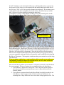
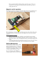
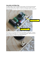
Assembly and Mounting
Assemble the parts as shown, and place on your avionics sled to locate the best position
for the Raven+Power Perch. Stack the 2 included restraint spacers together, with the
holes aligned with each other. Place the restraint spacer behind the battery with the holes
aligned as shown.
Restraint spacers
Magnetic Sensor
The magnetic sensor should be placed close to the airframe, no more than 1” from the
edge if using the small magnet, or 1.75” if using the large magnet. Either end can face
forward, with no loss of function in the flight configuration.
Drill the mounting holes for the restraint spacers.
If a 3/32” drill bit is used, the included 4-40 screws will thread themselves securely into
the plywood. If the screws are to be retained with the included nuts on the back side of
the sled, use a 7/64” or 1/8” bit to provide clearance for the threads. The restraint spacers
can be glued to each other and glued to the sled if desired. Install the battery restraint
with 1 screw to fix it into position for locating the other holes.
Use the Raven + battery + Power Perch assembly to locate the mounting holes for the
Power Perch and the Raven. Drill 2 holes for the Power Perch.
Battery Restraint
Either mark the holes and drill, or simply drill through the board mounting holes with the
Power Perch in place. Install two 4-40 screws to secure the Power Perch to the sled. No
spacers are required as long as the sled is made of an insulating material such as wood or
fiberglass (Not carbon fiber or Aluminum!) Note that the two Power Perch mounting
holes are also electrical terminals that can be used to provide power to a low-powered
accessory compatible with single-Lipoly cell operation, such as an RDF beacon from Big
Red Bee or Telemetrum. The magnetic switch turns that power terminal on and off along
with the Raven.
If you are using a conductive or semi-conductive sled, use nylon screws and spacers
(not included) to isolate the Power Perch from the sled, or else a short circuit will
result when the magnetic switch is turned on.
The end of the Raven with the screw terminals is adequately restrained via the Perch and
the screw terminals. There are 2 options for restraining the other end of the Raven.
1. Use the Raven’s original screw and spacer. This is the safest option, though it
does not provide the most convenient way to move a Raven from one Power
Perch to another.
2. Use the Raven restraint included in the Power Perch kit to hold down the aft end
of the Raven. Attach a spacer to the sled in the vicinity of the Raven’s aft
mounting hole to keep the Raven’s baro sensor from resting against the sled. The
Raven restraint then holds the Raven directly against the spacer. The user is
responsible for any damage to the Raven that may occur if the baro sensor is
resting against the sled.
Magnetic switch operation
The magnetic switch senses magnetic fields in the plane of the sled, perpendicular to its
edge. The included magnet should be oriented as shown below for optimum range.
m
ag
t
ne
The switch changes state when either end of the magnet leaves the vicinity of the sensor.
To turn the Raven on or off, put either end of the magnet close to the sensor and then
remove it.
Tips for trouble-free operation:
• Before use at the launch range, familiarize yourself with the correct magnet
orientation and the way the magnet changes the switch state when it is removed.
• If the sensor seems to “miss” the magnet movement, try moving the magnet more
slowly.
• Avoid magnetizing materials permanently connected to your av-bay sled. Do not
store the magnet in contact with a steel av-bay threaded rod, for example.
Battery Management
The Power Perch does not include a USB
port for charging the battery. To charge the
LiPo battery used in the av-bay, you will
need to provide your own charger, or obtain
a Featherweight USB Battery Charger.
To use the Featherweight USB Battery
Charger, plug the battery in to the board, the
connect the USB cable to the board, and finally to either a USB port on your computer, or
a USB wall wart. The LED on the board will be red while the battery is charging, and
will turn orange when charging is complete.
The charger takes care of charging the battery, and won't overcharge the cell unless there
is a failure in the system. Because of the (remote) possibility of failure, you should
take precautions when charging, such as not charging unattended or with
flammable material nearby. Never charged a cell that is damaged or that has its
cover puffed up.
When the charger's LED turns from red to orange, the cell is fully charged. If the cell has
been very discharged, it could take 1-2 hours to fully charge it. Usually the cell would
start out with a higher state of charge and it would take less time than that
Always recharge the battery and/or measure its voltage before flight. If it's less than 4 V,
a recharge is recommended. When the charger cuts off the charge and turns the LED
from red to orange, the cell's open-circuit voltage should be around 4.1-4.15 V.
While the LiPo battery included with the av-bay has a long life, there are limitations. The
magnetic switch used to turn the av-bay on and off consumes power, even when the unit
is powered down. Because of this, the av-bay should not be assembled with the battery
installed for extended periods. Up to a week is o.k., but after several weeks with the
battery assembled, the battery will be significantly run down.