1
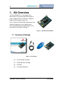
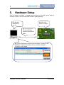
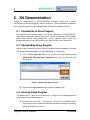
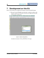
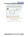
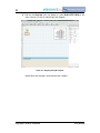
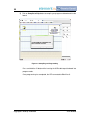
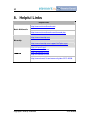
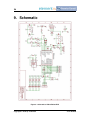
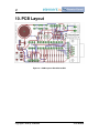
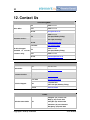
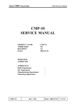
i
PIC18F26J50-EVK
User Manual
Rev.1.0 -- December 05, 2011
Copyright © 2011 by element14
User Manual
ii
Revision History
Rev
Date
Description
0.9
11/25/2011
Initialization
1.0
12/05/2011
Release version
Copyright © 2011 by element14
User Manual
iii
Table of Contents
1.
Kit Overview ..................................................................... 1
1.1
Contents of Package .................................................................................. 1
2.
Antistatic Precautions ..................................................... 2
3.
Pin Definition of Connectors........................................... 3
3.1
3.2
4.
Board Layout .............................................................................................. 3
Pin Definition .............................................................................................. 3
Software Installation ........................................................ 5
4.1
4.2
4.3
4.4
Software Introduction .................................................................................. 5
Software Download..................................................................................... 5
System requirement ................................................................................... 5
Software Installation ................................................................................... 5
5.
Hardware Setup ................................................................ 7
6.
Kit Demonstration ............................................................ 8
6.1
6.2
6.3
Introduction to Demo Program .................................................................... 8
Downloading Demo Program ...................................................................... 8
Running Demo Program ............................................................................. 8
7.
Development on this Kit ................................................ 10
8.
Helpful Links ................................................................... 15
9.
Schematic ....................................................................... 16
10. PCB Layout ..................................................................... 17
11. Bill of Materials............................................................... 18
12. Contact Us ...................................................................... 19
Copyright © 2011 by element14
User Manual
1
1. Kit Overview
The PIC18F26J50-EVK is a development and
demonstration kit designed to provide developers a
hands-on approach to learn Flowcode 4 (Graphical
Programming Languages) more easily.
The kit is based on PIC18F26J50 microcontroller, and
integrates temperature sensor, capacitor touch
sensor and potentiometer to help developers verify
their programs designed by Flowcode 4.
Figure 1–1 PIC18F26J50 EVK Board
1.1 Contents of Package
Figure 1–2 Kit Package
1 x PIC18F26J50-EVK board
1 x USB Cable (Mini USB type)
1 x CD-ROM
1 x One page Package list
Copyright © 2011 by element14
User Manual
2
2. Antistatic Precautions
Please make sure that an antistatic strap is grounded and used on your wrist
before taking out the kit from antistatic bag.
Please make sure that all the four rubber feet are attached to bottom of kit when
it is unpacked.
Please always handle the kit on a non-conducting surface.
Copyright © 2011 by element14
User Manual
3
3. Pin Definition of Connectors
This section will briefly introduce the connectors used on PIC18F26J50-EVK board and the
pins of these connectors in terms of definition, function and applications.
3.1 Board Layout
Figure 3–1 Kit Layout
As shown in the figure above, five connectors marked as CN1, CN2, CN3, CN4 and CN5
are mounted on the kit. Please refer to the following section for details.
3.2 Pin Definition
1)
CN1: ICSP Connector
ICSP (In-Circuit Serial Programming) is a serial program interface of Microchip,
it is used to program Microchip’s PIC and dsPIC series MCU. Please see the
Pin definition and description of ICSP as below:
Pin No.
Name
Description
1
MCLP
Master Clear (Reset) input
2
3.3V
3.3V Power Supply
Copyright © 2011 by element14
User Manual
4
Pin No.
Name
Description
3
GND
Ground
4
PGD
ICSP Data.
5
PGC
ICSP Clock.
6
NC
Not Use
2)
CN2: PICKIT Serial Connector
Pin
Name
Description
1
RXD1
Asynchronous serial receive data input
2
3.3V
3.3V Power Supply Output
3
GND
Ground
4
SDA
I2Cdata input/output
5
SCL
I2C clock input/output
6
TXD1
EUSART1 asynchronous transmit
3)
CN3: Mini USB
Pin No.
Name
Description
1
VDD
+5V Power Supply
2
D-
Differential data signal: Negative
3
D+
Differential data signal: Positive
4
NC
ID Pin, not use
5
GND
Ground
4)
CN4: OUTPUT
Pin No.
Name
Description
1
GND
Ground
2
3.3V
3.3V Power Supply Output
5)
CN5: E-Blocks Connectors
Unused
Copyright © 2011 by element14
User Manual
5
4. Software Installation
The related software should be installed on your PC prior to hardware connection so that the
kit could be working properly.
4.1 Software Introduction
1)
Flowcode 4
Flowcode 4 is one of the world’s most advanced graphical programming
languages for microcontrollers. The great advantage of Flowcode is that it
allows those with little experience to create complex electronic systems in
minutes.
2)
HID Bootloader
HID Bootloader functions as a bridge between Flowcode 4 and hardware to
allow users easily download program to their hardware (e.g. PIC18F26J50-EVK
board) through USB cables.
4.2 Software Download
A free version of Flowcode 4 for PICmicros, which is suitable for the Microchip PIC18
Starter Kit for Flowcode by element14, can be downloaded from the link shown below.
http://www.matrixmultimedia.com/lc_index.php?p=26
Also the free version as well as HID Bootloader can be found in the CD-ROM attached
with the kit.
4.3 System requirement
Personal computer with USB 1.0 or 2.0
Pentium processor or greater
Windows XP or later with Net Framework v4.0.30319 installed
256MB RAM
100MB hard disk space
4.4 Software Installation
1)
Flowcode 4
The Flowcode installation routine will guide you through the installation process
Copyright © 2011 by element14
User Manual
6
including the installation of any subsidiary programs or tools required by the
software.
When asked to select the default programmer, you can choose either E-blocks
or PICkit2. This choice is ignored when using the Microchip PIC18 Starter Kit for
Flowcode by element14.
2)
HID Bootloader
Please follow the installation guide to complete the process.
Copyright © 2011 by element14
User Manual
7
5.
Hardware Setup
After the software installation is complete, please follow the illustration shown below to
connect the kit to PC with the USB cable included in product package.
(2). Press and
hold the S1 button.
(1). Start HID
Bootloader on
your PC.
(3). Connect the kit to
PC with USB cable,
and then release the S1
button.
(4). PC will automatically install driver for new device, and then the HID
Bootloader’s interface which was previously ineffective would be
activated as shown below.
Copyright © 2011 by element14
User Manual
8
6. Kit Demonstration
Through the demonstration on PIC18F26J50-EVK, developers would have a general
understanding of how demo program works to display the signals detected by temperature
sensor, capacitive touch sensor and potentiometer through LED indicators on the kit.
6.1 Introduction to Demo Program
Demo program keeps tracking status of the sensors integrated on PIC18F26J50-EVK,
and display the detected signals by driving LEDs through I/O port on the kit. Developers
could switch around among temperature sensor, capacitive touch sensor and
potentiometer by pressing a push-button on the kit to view the results respectively.
6.2 Downloading Demo Program
After the steps illustrated in previous section 5 Hardware Setup are complete, you could
start to download demo program using HID Bootloader as shown below.
1) Click the button Open Hex File on the interface and select demo program
PIC18F26J50_EVK_Application_Program.hex in your hard drive to start
downloading.
Figure 6–1 Downloading Demo Program
2) Click the button Reset Device on the interface to reboot the kit.
6.3 Running Demo Program
The reboot process is quite fast, and now the kit is ready to test the demo program by
going through the following operations.
By default the sensor U3 is activated first. The LEDs on PIC18F26J50-EVK
change status when U3 detects temperature fluctuation caused by, for example,
putting your figure on the sensor.
Copyright © 2011 by element14
User Manual
9
Press the S1 button to switch to the on-board potentiometer P1 and turn it to
observe the status change of LEDs.
Press S1 again to switch to the capacitive touch sensor and touch the sensor
with your fingers to observe the status change of LEDs.
Copyright © 2011 by element14
User Manual
10
7. Development on this Kit
Now let’s start to make your first program with Flowcode 4 and PIC18F26J50-EVK board.
1) When you first load Flowcode you will be given a choice of creating a new
flowchart or opening an existing chart. Click on the first option and you will be
asked to choose a target device.
Figure 7–1 Choose a Target Device
Scroll down and select the “PIC18_STARTERKIT_E14” target.
Copyright © 2011 by element14
User Manual
11
2) You will see a Begin and End icon in the window marked ‘Main’. This is your
main program.
Menu
Toolbar
Component toolbox
Icon toolbox
Chip
Properties Pane
Simulation Panel
Figure 7–2 Main Program Window
Figure 7–3 Toolbar Icons’ Functions
The graphic above shows the functions of icons on the Toolbar. To find out what
an icon’s function is simply hold the mouse pointer over the icon and a small
‘tool tip’ will give you a clue.
Copyright © 2011 by element14
User Manual
12
3) From the Icon toolbox drag an Output icon onto the space between the Begin
and End icons. Then double click on the icon to bring up the properties window.
Figure 7–4 Output Properties Setting
Set the properties as shown. (Variable = 1, Port = PORTB, single bit).
Copyright © 2011 by element14
User Manual
13
4) Click on the Step Into icon (see below) or select RUN...STEP INTO on the
menu. You can use this to step through your program.
Figure 7–5 Stepping through Program
Notice B0 on the chip goes red to indicate logic 1 output.
Copyright © 2011 by element14
User Manual
14
5) Click on Compile to Chip button to compile your program and download it to the
board.
Figure 7–6 Compiling and Programming
Press and hold the S1 button while inserting the USB cable to put the board into
program mode.
Once programming has completed, the LED connected to B0 will be lit.
Copyright © 2011 by element14
User Manual
15
8. Helpful Links
Helpful Links
http://www.matrixmultimedia.com
Matrix Multimedia
http://www.matrixmultimedia.com/flowcode.php
http://www.microchip.com
Microchip
http://www.microchip.com/support/HotTopics.aspx
element14
http://uk.farnell.com/
http://us.element14.com/
http://sg.element14.com/
http://cn.element14.com/
http://www.element14.com/community/docs/DOC-40330
Copyright © 2011 by element14
User Manual
16
9. Schematic
Figure 9–1 Schematic of PIC18F26J50-EVK
Copyright © 2011 by element14
User Manual
17
10. PCB Layout
Figure 10–1 PCB Layout of PIC18F26J50-EVK
Copyright © 2011 by element14
User Manual
18
11. Bill of Materials
location
U1
U2
U3
LED 1
LED 2
LED 3
LED 4
LED 5
LED 6
LED 7
LED 8
S1
S2
P1
VR1
R13
R14
R15
R16
R17
R18
R19
R20
R4
R7
R10
R11
R12
R21
R22
R1
R8
R9
R23
R2
R3
R5
R6
C1
C3
C4
C5
C6
C2
C7
C8
C9
CN1
CN2
CN4
CN3
CN5
Qz1
Order
Code
1706309
1331271
1605577
1710526
1710526
1710526
1710526
1710526
1710526
1710526
1710526
1863398
1863398
9352651
9238484
9238484
9238484
9238484
9238484
9238484
9238484
9238484
9238360
9238360
9238360
9238360
9238360
9238360
9238360
9238603
9238603
9238603
9238603
9238247
9238247
9238565
9238565
1657936
1657936
1657936
498543
498543
317287
317287
317287
317287
1593430
1593430
1624224
1696539
1099294
1667001
Part No.
PIC18F26J50-I/SP
24AA02-I/P
MCP9700AT-E/TT
ASMT-RJ45-AQ502
ASMT-RJ45-AQ502
ASMT-RJ45-AQ502
ASMT-RJ45-AQ502
ASMT-RJ45-AQ502
ASMT-RJ45-AQ502
ASMT-RJ45-AQ502
ASMT-RJ45-AQ502
3-1825910-5
3-1825910-5
3266W-1-103LF
MCP1804T-3302I/DB SOT223
RC0603FR-071KL
RC0603FR-071KL
RC0603FR-071KL
RC0603FR-071KL
RC0603FR-071KL
RC0603FR-071KL
RC0603FR-071KL
RC0603FR-071KL
RC0603FR-07100RL
RC0603FR-07100RL
RC0603FR-07100RL
RC0603FR-07100RL
RC0603FR-07100RL
RC0603FR-07100RL
RC0603FR-07100RL
RC0603FR-0710KL
RC0603FR-0710KL
RC0603FR-0710KL
RC0603FR-0710KL
RC0603FR-0710RL
RC0603FR-0710RL
RC0603FR-074K7L
RC0603FR-074K7L
08056C106KAT2A
08056C106KAT2A
08056C106KAT2A
06035A220JAT2A
06035A220JAT2A
06033G104ZAT2A
06033G104ZAT2A
06033G104ZAT2A
06033G104ZAT2A
MC34751
MC34751
EBV-02-D
MC32598
8LCM009S-304B-XX
HC49S-12-30-50-70-30-ATF
Copyright © 2011 by element14
Description
MCU, 8BIT, 64K FLASH, NANOWATT, 28SPDIP
IC, EEPROM SERIAL 2KB, SMD, PDIP8
THERMAL SENSOR, 2.3 ~5.5V, SOT23-3
LED, SMD, 0603, ORANGE
LED, SMD, 0603, ORANGE
LED, SMD, 0603, ORANGE
LED, SMD, 0603, ORANGE
LED, SMD, 0603, ORANGE
LED, SMD, 0603, ORANGE
LED, SMD, 0603, ORANGE
LED, SMD, 0603, ORANGE
SWITCH, PUSHBUTTON, SPST
SWITCH, PUSHBUTTON, SPST
TRIMMER, 12 TURN 10K
LDO 3.3V OUTPUT, CMOS 28V, SOT223-3
RESISTOR, 1K, 100MW, 1%
RESISTOR, 1K, 100MW, 1%
RESISTOR, 1K, 100MW, 1%
RESISTOR, 1K, 100MW, 1%
RESISTOR, 1K, 100MW, 1%
RESISTOR, 1K, 100MW, 1%
RESISTOR, 1K, 100MW, 1%
RESISTOR, 1K, 100MW, 1%
RESISTOR, RC22H, 0603, 100R
RESISTOR, RC22H, 0603, 100R
RESISTOR, RC22H, 0603, 100R
RESISTOR, RC22H, 0603, 100R
RESISTOR, RC22H, 0603, 100R
RESISTOR, RC22H, 0603, 100R
RESISTOR, RC22H, 0603, 100R
RESISTOR, 10K , 100MW, 1%
RESISTOR, 10K , 100MW, 1%
RESISTOR, 10K , 100MW, 1%
RESISTOR, 10K , 100MW, 1%
RESISTOR, RC22H 0603 10R
RESISTOR, RC22H 0603 10R
RESISTOR, RC22H, 0603, 4K7, 1%
RESISTOR, RC22H, 0603, 4K7, 1%
CAPACITOR, 10 UF, 6.3V, 0805, X7R
CAPACITOR, 10 UF, 6.3V, 0805, X7R
CAPACITOR, 10 UF, 6.3V, 0805, X7R
CAPACITOR, 0603, 22PF, 50V
CAPACITOR, 0603, 22PF, 50V
CAPACITOR, 0603, 100NF, 25V, Y5V
CAPACITOR, 0603, 100NF, 25V, Y5V
CAPACITOR, 0603, 100NF, 25V, Y5V
CAPACITOR, 0603, 100NF, 25V, Y5V
HEADER, 1 ROW, R/ANGLE, 6WAY
HEADER, 1 ROW, R/ANGLE, 6WAY
TERMINAL BLOCK, EUROSTYLE, 2POS 24-12AWG
SOCKET, MINI USB, PCB, TYPE AB, SMT
SOCKET, D, PCB, R/A, 9WAY
CRYSTAL, HC-49/S, 12.0MHZ
Manufacturer
MICROCHIP
MICROCHIP
MICROCHIP
AVAGO TECHNOLOGIES
AVAGO TECHNOLOGIES
AVAGO TECHNOLOGIES
AVAGO TECHNOLOGIES
AVAGO TECHNOLOGIES
AVAGO TECHNOLOGIES
AVAGO TECHNOLOGIES
AVAGO TECHNOLOGIES
TE CONNECTIVITY / AMP
TE CONNECTIVITY / AMP
BOURNS
MICROCHIP
YAGEO (PHYCOMP)
YAGEO (PHYCOMP)
YAGEO (PHYCOMP)
YAGEO (PHYCOMP)
YAGEO (PHYCOMP)
YAGEO (PHYCOMP)
YAGEO (PHYCOMP)
YAGEO (PHYCOMP)
YAGEO (PHYCOMP)
YAGEO (PHYCOMP)
YAGEO (PHYCOMP)
YAGEO (PHYCOMP)
YAGEO (PHYCOMP)
YAGEO (PHYCOMP)
YAGEO (PHYCOMP)
YAGEO (PHYCOMP)
YAGEO (PHYCOMP)
YAGEO (PHYCOMP)
YAGEO (PHYCOMP)
YAGEO (PHYCOMP)
YAGEO (PHYCOMP)
YAGEO (PHYCOMP)
YAGEO (PHYCOMP)
AVX
AVX
AVX
AVX
AVX
AVX
AVX
AVX
AVX
MULTICOMP
MULTICOMP
MULTICOMP
MULTICOMP
MULTICOMP
MULTICOMP
User Manual
19
12. Contact Us
United Kingdom
Sales Office
Tel
08447 11 11 11
Fax
08447 11 11 12
E-mail
[email protected]
08447 11 11 13
Tel
(8am-8pm, Monday-Friday)
Customer Services
Technical Support
(Available
to
(9am-12pm, Saturday)
E-mail
[email protected]
Live Chat
Live Technical Chat
08447 11 11 22
Tel
(8am-6pm, Monday-Friday)
account
customers only)
Fax
08447 11 11 23
E-mail
[email protected]
North America
Tel
800-463-9275
Quotation Link
Request a Quotation
Tel
800-463-9275
E-mail
Send an E-mail
Live Chat
Live Technical Chat
Sales Office
Customer Services
Technical Support
1.877.736.4835
Tel
(EST 8am-8pm, Monday-Friday)
E-mail
Send an E-mail
China
Shanghai: (86) 21 6196 1388
Beijing: (86) 10 5632 3688
Sales/Customer Office
Tel
Chengdu: (86) 28 6685 1888
Shenzhen: (86) 755 8305 4888
Hongkong: (852) 2268 9888
Copyright © 2011 by element14
User Manual
20
China
E-mail
[email protected]
Tel
(86) 400 820 3793
E-mail
[email protected]
Technical Support
Copyright © 2011 by element14
User Manual
21
Disclaimers & Trademarks
General — Information in this document is believed to be accurate and reliable. However,
element14 does not give any representations or warranties, expressed or implied, as to the
accuracy or completeness of such information and shall have no liability for the
consequences of use of such information.
Right to make changes — element14 reserves the right to make changes to information
published in this document, including without limitation specifications and product
descriptions, at any time and without notice. This document supersedes and replaces all
information supplied prior to the publication hereof.
Suitability for use — element14 products are not designed, authorized or warranted to be
suitable for use in medical, military, aircraft, space or life support equipment, nor in
applications where failure or malfunction of an element14 product can reasonably be
expected to result in personal injury, death or severe property or environmental damage.
element14 accepts no liability for inclusion and/or use of element14 products in such
equipment or applications and therefore such inclusion and/or use is at the customer’s own
risk.
Applications — Applications that are described herein for any of these products are for
illustrative purposes only. Element14 makes no representation or warranty that such
applications will be suitable for the specified use without further testing or modification.
Limiting values — Stress above one or more limiting values (as defined in the Absolute
Maximum Ratings System of IEC 60134) may cause permanent damage to the device.
Limiting values are stress ratings only and operation of the device at these or any other
conditions above those given in the Characteristics sections of this document is not implied.
Exposure to limiting values for extended periods may affect device reliability.
Terms and conditions of sale — element14 products are sold subject to the general terms
and conditions of commercial sale, as published at http://www.nxp.com/profile/terms,
including those pertaining to warranty, intellectual property rights infringement and limitation
of liability, unless explicitly otherwise agreed to in writing by element14. In case of any
inconsistency or conflict between information in this document and such terms and conditions,
the latter will prevail.
No offer to sell or license — Nothing in this document may be interpreted or construed as
an offer to sell products that is open for acceptance or the grant, conveyance or implication of
any license under any copyrights, patents or other industrial or intellectual property rights.
Trademarks — All referenced brands, product names, service names and trademarks are
the property of their respective owners.
Copyright © 2011 by element14
User Manual