1
99 Washington Street
Melrose, MA 02176
Fax 781-665-0780
TestEquipmentDepot.com
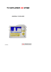
PRODIG-5
EXPLORADOR UNIVERSAL DE TV
UNIVERSAL TV EXPLORER
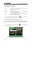
SAFETY NOTES
Read the user’s manual before using the equipment, mainly " SAFETY RULES "
paragraph.
The symbol
on the equipment means "SEE USER’S MANUAL". In this
manual may also appear as a Caution or Warning symbol.
Warning and Caution statements may appear in this manual to avoid injury
hazard or damage to this product or other property.
- 0 MI1384 -
USER’S MANUAL. PRODIG-5
O F
C O N T E N T S
1
GENERAL.................................................................................................................. 1
1.1 Description .......................................................................................................... 1
1.2 Specifications ...................................................................................................... 4
2
SAFETY RULES........................................................................................................ 9
2.1 General safety rules ............................................................................................ 9
2.2 Descriptive Examples of Over-Voltage Categories ........................................... 11
3
INSTALLATION ....................................................................................................... 13
3.1 Power Supply .................................................................................................... 13
3.1.1 Operation using the External DC Charger .................................................. 13
3.1.2 Operation using the Battery ........................................................................ 13
3.1.2.1
Battery Charging ............................................................................... 14
3.2 Installation and Start-up .................................................................................... 14
4
QUICK USER GUIDE .............................................................................................. 15
5
OPERATING INSTRUCTIONS................................................................................ 19
5.1 Description of the Controls and Elements ......................................................... 19
5.2 Adjustment of Volume and Monitor Parameters................................................ 26
5.3 Selecting the Operation Mode: TV / Spectrum Analyser / Measurements ........ 27
5.4 Channel Tuning / Frequency Tuning ................................................................. 27
5.5 Automatic Transmission Search........................................................................ 28
5.6 Selecting the measurement configuration: Analogue/ Digital signal ................. 28
5.7 External Units Power Supply............................................................................. 28
5.8 Automatic signal identification function (AUTO ID) ........................................... 29
5.9 Channel plans ................................................................................................... 30
5.10 Spectrum exploration function (EXPLORER).................................................... 32
5.11 Measurements configuration ............................................................................. 32
5.11.1 DVB-C (QAM) Digital Channel Configuration ............................................. 33
5.11.2 DVB-T (COFDM) Digital Channel Configuration......................................... 34
5.11.3 DVB-S (QPSK) Digital Channel Configuration............................................ 35
5.12 Selecting the Measurements............................................................................. 37
5.12.1 Analogue TV: Measuring the Video Carrier Level....................................... 38
5.12.2 Analogue TV: Measuring the Video / Audio ratio (V/A)............................... 40
5.12.3 Analogue/Digital TV: Measuring the Carrier / Noise ratio (C/N).................. 40
5.12.4 Digital TV: Measuring the Power of Digital Channels ................................. 42
5.12.5 Digital TV: Measuring BER ......................................................................... 42
5.12.5.1
DVB-C signals................................................................................... 43
5.12.5.2
DVB-T signals ................................................................................... 44
5.12.5.3
DVB-S signals................................................................................... 46
5.12.6 Digital TV: Measuring MER......................................................................... 48
5.13 Spectrum Analyser ............................................................................................ 50
5.13.1 Markers ....................................................................................................... 51
5.14 TV Operating Mode ........................................................................................... 51
5.15 Antenna Alignment Function ............................................................................. 53
English
T A B L E
USER’S MANUAL. PRODIG-5
5.16 DiSEqC Command Generator........................................................................... 54
6
DESCRIPTION OF THE INPUTS AND OUTPUTS ................................................. 55
6.1 RF input............................................................................................................. 55
6.2 RS-232C serial port........................................................................................... 55
6.3 Scart (DIN EN 50049) ....................................................................................... 56
7
MAINTENANCE ..................................................................................................... 57
7.1 Considerations about the Screen. ..................................................................... 57
7.2 Cleaning Recommendations ............................................................................. 57
USER’S MANUAL. PRODIG-5
UNIVERSAL TV EXPLORER
PRODIG-5
1
1 GENERAL
1.1
Description
This equipment incorporates important advances in the functional aspects as in
the ergonomics to allow the installers to make their work with the maximum comfort
and speed. Simultaneously the instrument is reliable front any possible problem at he
input signal, at the distribution components or the receiver equipments.
The PRODIG-5 has been designed to satisfy all the necessities of measurement
during the transition from the analogue transmissions to the digital in the
terrestrial, satellites and cable systems. Allowing to take measurements of analogue
signals as much digital ones. When pressing the auto identification key, it searches
and identifies the signal under test. First it recognises whether the signal is an
analogue channel or a digital one. If the channel is analogue, it determines the
television standard of the signal. When the signal is digital (DVB), it analyses for each
modulation type QAM / QPSK / COFDM all the associated parameters such as the
modulation system: carriers 2k-8k, symbol rate, code rate, etc.,. and determines the
value of the signals under test.
The PRODIG-5 includes the main TV standards: M, N, B, G, I, D, K and L,
adopting, apart from the characteristic parameters of the standard, the correcting
automatic system to obtain in all the cases an accurate measuring of the input signal
level. It admits any TV system (PAL, SECAM and NTSC) and allows the user to work
directly with digital TV signals decoding them, so that the television image may be
viewed, and directly measuring the power, carrier/noise ratio (C/N), the bit error rate
(BER) and the modulation error ratio (MER), as well for DVB-T (COFDM) as DVB-S
(QPSK) and DVB-C (QAM) signals. Being a multistandard instrument, it can be
efficiently used in any country of the world.
1
09/2005
Trade Mark of the DVB Digital Video Broadcasting.
Page 1
English
The television explorer PRODIG-5 (EXPLORER) represents an evolution step with
respect to the traditional field strength meters. The continuous PROMAX innovation
process in the sector of field strength meter yields an equipment that changes the form
to take and to understand the television signals measurements.
USER’S MANUAL. PRODIG-5
Includes a symbol-based keyboard that allows the direct access to the various
functions that are displayed simultaneously on screen.
The PRODIG-5 makes a dynamic exploration of the spectrum, detecting all the
channels in the explored band, this applies for the terrestrial and the satellite
television bands. The meter locates all the channels in the spectrum with no need of
any previous information about the number of channels, the type of signals
transmitted or their characteristics. With the data collected after each exploration, it
creates a register that contains tables of channels that can be independent for each
system or installation. At any time, the measurement sessions using only the
pretuned channels can be repeated. In this way it is possible to optimise the
measurement process.
On the frontal panel appears showed the type of measurement that is being
carried (Terrestrial-Satellite/Analogue-Digital) and the data are visualised by means of a
hi-res 5" graphic TFT display. The equipment incorporates a light sensor that activates
the contrast and luminosity of the display according to the environmental conditions.
The EXPLORER has an ideal size to hold with a hand. The instrument can be
held to the body with the carrying bag which at the same time protects it from the rain.
Especially considering its outdoor use, includes an anti-shock protector that completely
covers the instrument, and optionally can be supplied with a strong transport case.
Besides the front panel does not have any keys nor gaps to avoid accidental water
ingress.
The PRODIG-5 is designed to integrate measurements that require different
operating configurations. In this way it incorporates a specific function to facilitate the
alignement of antennas. When activating it the instrument is set automatically to offer
a fast spectrum sweep and a high sensitivity graphical bar allows the fine adjust of
the maximums of signal. In addition it includes a module for the feeding of LNBs, and
DVB-T antennas to 5V. As well as the commands for the programming of DiSEqC 1.2
devices.
The EXPLORER allows to be updated to new software versions that extend the
available functions in the future. That means to incorporate new benefits without
additional cost. For example the test of satellite signals distribution networks. The
use in combination with an IF generator allows to carry out an easy verification of the
installations before the operation beginning.
The spectrum analyser features with high accuracy, resolution, sensitivity and
sweep speed can do the instrument very useful for applications as the installation of
antennas or the detection of complex impulsional noise events. It presents an
innovative control system based on four arrows, that makes the use of the spectrum
analyser very intuitive. The arrows allow adjusting the reference level by steps of 10dB
and the frequency margin span on screen.
Page 2
09/2005
Test Equipment Depot - 800.517.8431 - 99 Washington Street Melrose, MA 02176
FAX 781.665.0780 - TestEquipmentDepot.com
USER’S MANUAL. PRODIG-5
Also, the meter incorporates a DiSEqC2 command generator and permits to
supply different voltages to the external unit (5 V / 13 V / 15 V / 18 V / 24 V) and
includes an EUROCONNECTOR, or Scart connector, for audio/video input/output.
The PRODIG-5 is powered by rechargeable battery or connected to the mains
through the supplied external DC power charger.
It incorporates a RS-232C interface, which enables to carry out the checking,
setup and calibration processes.
English
This instrument due to its extreme-compact design, technical specifications and
low cost becomes the reference instrument for the installer.
2 DiSEqCTM is a trademark of EUTELSAT.
09/2005
Page 3
USER’S MANUAL. PRODIG-5
1.2
Specifications
CONFIGURATION FOR MEASURING LEVEL AND POWER
TUNING
Tuning modes
Resolution
Digital frequency synthesis. Continuous tuning from
45 to 865 MHz and from 950 to 2150 MHz
Chanel or frequency (If or forward at satellite band).
Channel plan configurable on demand
45-865 MHz: 50 kHz
950-2150 MHz: < 200 kHz (span FULL-500-200100-50-32-16 MHz).
Automatic search (Explorer)
Threshold level selectable. DVB-T or DVB-C
selection
Signal identification
Analogue and digital. Automatic.
RF INPUT
Impedance
Connector
Maximum signal
Maximum input voltage
DC to 100 Hz
45 MHz to 2150 MHz
75 Ω
Universal, with BNC or F adapter.
130 dBµV
50 Vrms (powered by the AL-103 power charger)
30 Vrms (not powered by the AL-103 power
charger)
130 dBµV
DIGITAL SIGNALS MEASUREMENT
POWER RANGE
COFDM:
QAM:
QPSK:
45 dBµV to 100 dBµV.
45 dBµV to 110 dBµV.
44 dBµV to 114 dBµV.
MEASUREMENTS
DVB-T (COFDM):
Presentation:
Power, CBER, VBER, MER, C/N
Numeric and level bar.
DVB-C (QAM):
Presentation:
Power, BER, MER, C/N
Numeric and level bar.
DVB-S (QPSK):
Presentation:
Power, CBER, VBER, MER, C/N
Numeric and level bar.
Page 4
09/2005
USER’S MANUAL. PRODIG-5
QAM SIGNAL PARAMETERS
Demodulation
Symbol rate
Roll-off (α) factor
of Nyquist filter
Spectral inversion
QPSK SIGNAL PARAMETERS
Symbol rate
Roll-off (α) factor
of Nyquist filter
Code Rate
Spectral inversion
VIDEO
Format
Services decoding
2k / 8k (Selected by the user).
1/4, 1/8, 1/16, 1/32 (Selected by the user).
1/2, 2/3, 3/4, 5/6, 7/8.
QPSK, 16-QAM, 64-QAM.
Selectable: ON, OFF.
Indicates hierarchy mode.
16/32/64/128/256 QAM.
1000 to 7000 kbauds.
0.15.
Selectable: ON, OFF
2 to 45 Mbauds.
0.35.
1/2, 2/3, 3/4, 5/6, 7/8 and AUTO.
Selectable: ON, OFF
English
COFDM SIGNAL PARAMETERS
Carriers
Guard Interval
Code Rate
Modulation
Spectral inversion
Hierarchy
MPEG-2 / DVB (MP@ML).
Service list and PIDs
ANALOGE SIGNALS MEASUREMENT
LEVEL MEASUREMENT
Measurement range
Terrestrial TV & FM bands
Satellite TV band
Reading
Digital
Analogue
Measurement bandwidth
Audible indicator
09/2005
10 dBµV to 120 dBµV (3.16 µV to 1 V)
30 dBµV to 120 dBµV (31.6 µV to 1 V)
Auto-range, reading is displayed on an OSD
window
Absolute value calibrated in dBµV, dBmV or dBm.
Relative value through an analogue bar on the
screen.
230 kHz (Terrestrial band) 4 MHz (Satellite band)
(maximum band ripple 1 dB).
LV audio. A tone with pitch proportional to signal
strength.
Page 5
USER’S MANUAL. PRODIG-5
Accuracy
Terrestrial bands
Satellite band
Overrange indication
MEASUREMENTS MODE
Terrestrial bands
Analogue channels
Digital channels
Satellite band
Analogue channels
Digital channels
SPECTRUM ANALYSER MODE
Satellite band
Terrestrial bands
Measurement bandwidth
Terrestrial
Satellite
Span
Terrestrial
Satellite
Markers
Measurements
Terrestrial bands
Analogue channels
Digital channels
Satellite band
Analogue channels
Digital channels
Page 6
±1.5 dB (30-120 dBµV, 45-865 MHz) (22 °C±5 °C)
±2.5 dB (40-100 dBµV, 950-2050 MHz) (22 °C ± 5 °C)
↑, ↓
Level, Video-Audio ratio and Carrier-Noise ratio..
Channel power, Carrier-Noise ratio and Channel
identification.
Level and Carrier-Noise ratio.
Channel power and Carrier-Noise ratio.
30 dBµV to 120 dBµV (31.6 µV to 1 V)
10 dBµV to 120 dBµV (3.16 µV to 1 V)
230 kHz
4 MHz
Full span (full band) - 500 - 200 - 100 - 50 - 32 - 16
- 8 MHz selectable.
Full span (full band) - 500 - 200 - 100 - 50 - 32 - 16
MHz selectable.
1 with Frequency and level indications..
Level.
Channel power.
Level.
Channel power.
09/2005
USER’S MANUAL. PRODIG-5
MONITOR DISPLAY
Monitor
Colour system
TV standard
Spectrum mode
Sensibility
TFT colour 5 inches.
PAL, SECAM and NTSC
M, N, B, G, I, D, K and L
Variable span, dynamic range and reference level
by means of arrow cursors.
40 dBµV for correct synchronism.
BASE BAND SIGNAL
SOUND
Input
Outputs
Demodulation
De-emphasis
Subcarrier
Scart.
1 Vpp (75 Ω) positive video
Scart (75 Ω)
Scart
Built in speaker, Scart.
TV PAL, SECAM, NTSC system according to DVBT, DVB-C, DVB-S and MPEG standards.
50 µs
Digital frequency synthesis according to the TV
standard.
RS-232C INTERFACE
For service and calibration.
EXTERNAL UNITS POWER
SUPPLY
Terrestrial and Satellite
22 kHz signal
Voltage
Frequency
Maximum power
Through the RF input connector.
External or 5/13/15/18/24 V
Selectable in satellite band.
0.6 V ± 0.2 V
22 kHz ± 4 kHz
5W
DiSEqC3 GENERATOR
According to DiSEqC 1.2 standard.
POWER SUPPLY
Internal
Batteries
Autonomy
Recharging time
External
Voltage
Consumption
3
English
VIDEO
External video input
Sensibility
Video output
7.2 V 11 Ah Li-Ion battery.
> 3.5 hours in continuous mode.
3 hours up to 80% (instrument off)
12 V
35 W
DiSEqCTM is a trademark of EUTELSAT.
09/2005
Page 7
Test Equipment Depot - 800.517.8431 - 99 Washington Street Melrose, MA 02176
FAX 781.665.0780 - TestEquipmentDepot.com
USER’S MANUAL. PRODIG-5
Auto power off
Programmable. After the selected amount of
minutes without operating on any control.
Deactivable.
OPERATING ENVIRONMENTAL CONDITIONS
Altitude
Up to 2000 m
Temperature range
From 5 to 40 °C (Automatic disconnection by
excess of temperature).
Max. relative humidity
80 % (up to 31°C),
decreasing lineally up to 50% at 40 °C.
MECHANICAL FEATURES
Dimensions
Weight
230 (W) x 161 (H) x 76 (D) mm
(Total size: 2.814 cm3)
1.9 kg (without holster)
INCLUDED ACCESSORIES
1x CB-044
Rechargeable Li+ battery 7,2 V 11 Ah
1x AD-055
"F"/F-BNC/F adapter
1x AD-056
"F"/F-"DIN"/F adapter
1x AD-057
"F"/F-"F"/F adapter
1x AL-103
External DC charger
1x DC-261
Carrying bag.
1x AA-103
Car lighter charger.
1x CA-005
Mains cord.
OPTIONAL ACCESSORIES
DC-299
Transport suitcase.
Page 8
09/2005
USER’S MANUAL. PRODIG-5
2 SAFETY RULES
2.1
General safety rules
*
Use this equipment connected only to systems with their negative of
measurement connected to ground potential.
*
The AL-103 external DC charger is a Class I equipment, for safety reasons plug it
to a supply line with the corresponding ground terminal.
*
This equipment can be used in Overvoltage Category I installations and
Pollution Degree 2 environments.
External DC charger can be used in Overvoltage Category II, installation and
Pollution Degree 1 environments.
*
When using some of the following accessories use only the specified ones to
ensure safety.
English
Rechargeable battery
External DC charger
Car lighter charger cable
Power cord
*
Observe all specified ratings both of supply and measurement.
*
Remember that voltages higher than 60 V DC or 30 V AC rms are dangerous.
*
Use this instrument under the specified environmental conditions.
*
When using the power adaptor, the negative of measurement is at ground
potential.
*
Do not obstruct the ventilation system of the instrument.
*
Use for the signal inputs/outputs, specially when working with high levels,
appropriate low radiation cables.
*
Follow the cleaning instructions described in the Maintenance paragraph.
09/2005
Page 9
USER’S MANUAL. PRODIG-5
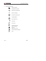
*
Symbols related with safety:
DIRECT CURRENT
ALTERNATING CURRENT
DIRECT AND ALTERNATING
GROUND TERMINAL
PROTECTIVE CONDUCTOR
FRAME TERMINAL
EQUIPOTENTIALITY
ON (Supply)
OFF (Supply)
DOUBLE INSULATION
(Class II Protection)
CAUTION
(Risk of electric shock)
CAUTION REFER TO MANUAL
FUSE
Page 10
09/2005
USER’S MANUAL. PRODIG-5
2.2
Descriptive Examples of Over-Voltage Categories
Low voltage installations isolated from the mains
Cat II
Portable domestic installations
Cat III
Fixed domestic installations
Cat IV
Industrial installations
English
Cat I
09/2005
Page 11
USER’S MANUAL. PRODIG-5
Page 12
09/2005
Test Equipment Depot - 800.517.8431 - 99 Washington Street Melrose, MA 02176
FAX 781.665.0780 - TestEquipmentDepot.com
USER’S MANUAL. PRODIG-5
3 INSTALLATION
3.1
Power Supply
The PRODIG-5 (EXPLORER) is a portable instrument powered by one 7.2 V - 11
Ah Li-Ion battery. There is also an external DC charger provided for mains connection
and battery charging.
3.1.1 Operation using the External DC Charger
Connect the external DC charger to EXT. SUPPLY [32] on the PRODIG-5
(EXPLORER) side panel. Connect the DC charger to the mains. Then, press the rotary
selector [1] for more than two seconds. The level meter is now in operation and the
battery is slowly charged. When the instrument is connected to the mains, the
CHARGER indicator [4] remains lit. This indicator changes of colour according to the
battery charge status:
ON
< 90 %
> 90 %
100 %
English
RED
YELLOW
GREEN
BATTERY CHARGE STATUS
OFF
< 50 %
> 50 %
100 %
Table 1.- Indication of the battery charge status (CHARGER).
3.1.2 Operation using the Battery
For the device to operate on the battery, disconnect the power cable and press
the rotary selector [1] for more than two seconds. The fully charged battery can power
the equipment for more than 3.5 hours non-stop.
If battery is very weak, the battery cut-off circuit will prevent the device from
functioning. In such a situation battery must be recharged immediately.
Before taking any measurements, you have to check the charge status of the
battery by checking the battery charge level indicator that appears when activating the
measurement mode pressing key
09/2005
[12]. These are the indicators on screen:
Page 13
USER’S MANUAL. PRODIG-5
COLOUR
GREEN
BATTERY CHARGE LEVEL INDICATORS
SYMBOL
CHARGE LEVEL
75 % ∼ 100 %
YELLOW
30 % ∼ 75 %
RED
10 % ∼ 30 %
< 10 %
Charge in progress.
Table 2.- Indication of the battery charge level on screen.
3.1.2.1
Battery Charging
To fully charge the battery, connect the instrument to the external DC charger
without activating the power on process. The length of time it takes to recharge it
depends on the condition of the battery. If they are very low the recharging period is
about 5 hours. The CHARGER [4] indicator should remain lit.
When the battery charging process is completed with the instrument off, the fan
stops.
IMPORTANT
The instrument battery needs to be kept charged between 30% and 50% of its capacity
when not in use. The battery needs to be fully charged for best results. A fully charged
battery suffers temperature-related discharge. For example, at a room temperature of
20 °C, it can lose up to 10% of its charge over 12 months.
3.2
Installation and Start-up
The PRODIG-5 (EXPLORER) level meter is designed for use as a portable device.
Therefore does not require installation
When the rotary selector [1] is pressed for more than two seconds, the instrument
is started up in the automatic power-off mode; that is, the device is automatically
disconnected after the selected minutes if no key has been pressed. When the device is
operating, it is also possible to select the auto power-off mode by means of the
Preferences menu [22] and to select the time out until the automatic power-off.
Page 14
09/2005
USER’S MANUAL. PRODIG-5
4 QUICK USER GUIDE
STEP 1.- Battery charging
1. Connect the DC external charger to the equipment through connector [32] located
on the lateral panel.
2. Connect the DC charger to the mains.
3. When the equipment is connected to the mains, the CHARGER led [4] remains
English
lighted.
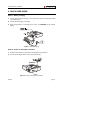
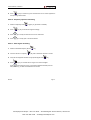
Figure 1.- Battery charging
STEP 2.- Power on and signal connection
1. Hold the rotary selector [1] pressed until the equipment is powered on.
2. Connect the RF signal source in the input connector [30].
Figure 2.- Power on and signal connection.
09/2005
Page 15
USER’S MANUAL. PRODIG-5
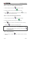
STEP 3.- To carry out a complete channel band exploration
1. Select the frequency band to explore
[14] (terrestrial or satellite).
2. Activate the exploration process by holding
[25] key pressed.
3. Press
[10] key to visualise the channels detected and
between channels from detected channels list.
[6] to change
STEP 4.- To carry out the tuned channel identification
1. Select the frequency band to explore
[14] (terrestrial or satellite).
2. Activate the identification process pressing once on
3. Press
[10] key to visualise the signal detected from channel or frequency
identified or
NOTE:
[25] key.
[13] to monitor the corresponding spectrum.
In the case that is desired to explore or identify DVB-C signals it is necessary
to select previously DVB-C standard as digital signal identifier through
[22] PREFERENCES menu.
STEP 5.- Taking measurements
1. Select the channel or frequency
[24] to measure by means of the rotary
selector [1].
Page 16
09/2005
USER’S MANUAL. PRODIG-5
2. Press
[12] key to select the type of measurement until on screen appears the
corresponding measurement.
STEP 6.- Frequency spectrum monitoring
1. Select the frequency band
2. Press
to graph [14] (terrestrial or satellite).
[13] key to activate the signals sweeping.
[6] to modify the reference level in the vertical axis.
4. Press
[6] to modify span in the horizontal axis.
English
3. Press
STEP 7.- Video signal monitoring
1. Select the terrestrial frequency band
2. Tune the channel or frequency
[14].
[24] that is desired to visualize on screen.
3. Verify that the equipment receives an appropriate signal level
4. Press
[12].
[10] key to visualise the TV image, if the channel is digital
press
[6] and place the cursor on the Service Identifier field and press the
rotary selector [1] to obtain the available list of services.
09/2005
Page 17
Test Equipment Depot - 800.517.8431 - 99 Washington Street Melrose, MA 02176
FAX 781.665.0780 - TestEquipmentDepot.com
USER’S MANUAL. PRODIG-5
Page 18
09/2005
USER’S MANUAL. PRODIG-5
5 OPERATING INSTRUCTIONS
WARNING:
The following described functions could be modified based on software updates of the
equipment, carried out after manufacturing and the publication of this manual.
5.1
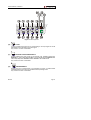
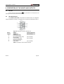
Description of the Controls and Elements
English
Front panel
Figure 3.- Front panel.
[1]
Rotary selector-button. This has many different functions: Equipment power
on/off, tuning control, moving between the various on-screen menus and submenus, and validation of the different options.
In order to power on the equipment, hold the rotary selector pressed for more
than two seconds until the presentation screen appears.
09/2005
Page 19
USER’S MANUAL. PRODIG-5
In order to power off the meter hold the rotary selector pressed.
Tuning purposes: turning it clockwise frequency increases while turning it
anticlockwise frequency decreases.
To move along the on-screen menus: turning it clockwise active option moves
downwards while turning it anticlockwise active option moves upwards.
[2]
EXT VIDEO. Video signal presence light indicator
It lights up when video on screen is coming through the SCART connector [35].
[3]
DRAIN
External units power supply indicator. Lights up when the PRODIG-5 (EXPLORER)
supplies a current to the external unit.
[4]
CHARGER
External DC charger operation indicator. When batteries are installed the battery
charger is automatically activated.
[5]
SENSOR
Sensor of environmental luminosity, allows automatic adjusts of the display
contrast and brightness contributing to the battery saving.
[6]
CURSORS
Allow adjust in the Spectrum Analyser mode of the reference level and the
margin of frequencies to represent (span). As well as the movement through the
different menus and submenus that appear in the monitor.
[7]
MONITOR
[8]
MAIN KEYBOARD
12 keys to select functions and entering alphanumeric data.
Page 20
09/2005
USER’S MANUAL. PRODIG-5
[10]
TV KEY
It allows visualising the image of TV corresponding to the input signal as well as
data relative to the reception of the video signal.
Key number 1 to enter numeric data.
[11]
EXTERNAL UNITS POWER SUPPLY
Enables selecting the power supply to the external units. Available voltages are:
External, 5 V, 13 V, 15 V, 18 V and 24 V for the terrestrial band and External, 5 V,
13 V, 15 V, 18 V, 13 V + 22 kHz and 18 V + 22 kHz for the satellite band.
Key number 2 to enter numeric data.
[12]
MEASUREMENTS
Enables the type of measurement to be selected. The types of measurements
available depend on the band, the standard and the operating mode.
Key number 3 to enter numeric data.
09/2005
Page 21
English
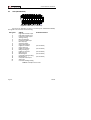
Figure 4.- Main keyboard
USER’S MANUAL. PRODIG-5
[13]
SPECTRUM/TV
Allows switching between any previous operating mode and the Spectrum
Analyser mode and viceversa.
Key number 4 to enter numeric data.
[14]
SATELLITE/TERRESTRIAL BAND
Allows switching between the Satellite or Terrestrial TV frequency band.
Key number 5 to enter numeric data.
[15] S
This led remains lighted when the equipment works with the frequencies and the
corresponding channels to the satellite band.
[16] T
This led remains lighted when the equipment works with the frequencies and the
corresponding channels to the terrestrial band.
[17]
MEASUREMENT CONFIGURATION
It allows the commutation between the measurement mode for Digital TV or
Analogue TV.
[18] D
This led remains lighted when the equipment works with digital signals.
[19] A
This led remains lighted when the equipment works with analogue signals.
[20]
IMAGE ADJUST
Activation of VOLUME, CONTRAST, BRIGHT, SATURATION and HUE (only for
NTSC colour system) control menus.
Key number 6 to enter numeric data.
Page 22
09/2005
Test Equipment Depot - 800.517.8431 - 99 Washington Street Melrose, MA 02176
FAX 781.665.0780 - TestEquipmentDepot.com
USER’S MANUAL. PRODIG-5
[21]
DISEQC
(Only in satellite band). It allows adjusting configuration parameters in satellite
band.
Key number 7 to enter numeric data.
[22]
UTILITIES / PREFERENCES
It activates the Utilities menu (short pulsation):
Equipment Info.
Displays information on the instrument: serial number,
version of control software, included set-up, etc.
Modify Channel Plan
Deletes Channel Plan selected.
Exit
Exit from Utilities.
Language
Selects the language between DEUTSCH, ENGLISH,
ESPAÑOL, FRANÇAIS, and ITALIANO.
Beep
Activates (ON) / deactivates (OFF) the beeper.
Skin
Sets the screen background colour.
Light Sensor
Activates the environmental luminosity sensor [5], to
automatically adjust the resistance and brightness of
the display.
Ter. Identify
Selects the type of terrestrial digital signal, DVB-C or
DVB-T used by AUTO-ID and EXPLORER functions.
Min. Ter. Power
Minimum level of digital signal to display. (Between 0.0
dBµV and 130.0 dBµV)
Min. Ter. Level
Minimum level of analogue signal to display. (Between
0.0 dBµV and 130.0 dBµV).
Min. Sat. Power
Minimum level of digital signal to display
Auto Power Off
Activates the automatic power off mode.
09/2005
Page 23
English
It activates the Preferences menu (long pulsation):
USER’S MANUAL. PRODIG-5
Time Power Off
Select the power off timeout between 1 and 120
minutes.
Units
Select the measurements units: dBµV, dBmV or dBm.
Rotary Selector
Select the movement sense: CW (clockwise) or CCW
(counterclockwise).
Exit
Exit from preferences menu
Key number 8 to enter numeric data.
[23]
ANTENNA ALIGNMENT
Tool for faster sweep antenna alignment at terrestrial and satellite bands.
Displays the measurements by means of a graph level bar.
Key number 9 to enter numeric data.
[24]
TUNING BY CHANNEL OR FREQUENCY
Switches tuning mode between channel and frequency. In channel mode the
tuning frequency is defined by the active channels table (CCIR, ...).
Key number 0 to enter numeric data.
[25]
AUTO ID/ EXPLORER
Activates the automatic identification function (short pulsation):
The instrument will try to identify the signal under test.
First it recognises whether the signal is an analogue channel or a digital one.
If the channel is analogue, it determines the television standard of the signal
detected.
When the signal is digital, it analyses the modulation type: QAM / QPSK /
COFDM and all the associated parameters such as the carriers 2k-8k, the
symbol rate, the code rate, etc and it tries to lock to the signal.
Activates the band exploration function (long pulsation):
The meter explores the entire frequency band to identify the analogue and
digital channels present.
Page 24
09/2005
USER’S MANUAL. PRODIG-5
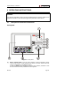
Figure 5.- Top panel view.
RF signal input
[30] RF
Maximum level 130 dBµV. Universal connector for F/F or F/BNC adapter, with
input impedance of 75 Ω.
ATTENTION
Note the importance to protect the RF
[30] input signal with an
accessory to block the AC voltages used in CATV cables (needed to feed
the amplifiers) and remote mode.
Figure 6.- Lateral panel connectors.
09/2005
Page 25
USER’S MANUAL. PRODIG-5
[31] RESET button
Enables the user to restart the instrument if there is any irregularity when
operating.
[32] External 12 V power supply input
[33] Loudspeaker
[34] Fan
[35] SCART connector
Figure 7.- Rear panel view.
[36] RS-232C Connector
For maintenance and calibration processes.
5.2
Adjustment of Volume and Monitor Parameters
[3] key sequentially activates the VOLUME,
Repeatedly pressing the
CONTRAST, BRIGHTNESS, SATURATION and HUE control menus (this last only for
NTSC colour system). On activation of a menu for a specific parameter the screen
displays a horizontal bar whose length is proportional to the parameter level, to modify
this value simply turn the rotary selector [1]. To exit the menu and validate the new
value press the rotary selector [1].
Page 26
09/2005
USER’S MANUAL. PRODIG-5
5.3
Selecting the Operation Mode: TV / Spectrum Analyser /
Measurements
The PRODIG-5 (EXPLORER) has three basic operation modes: TV, Spectrum
Analyser and Measurements. To switch from TV operation mode to the Spectrum
Analyser press
key.
[13] key. To switch to the Measurements mode press
[12]
In the TV operation mode the demodulated television signal is shown on-screen;
this is the default operation mode, various functions can be selected, as shown in the
following paragraphs.
In the Spectrum Analyser operation mode the screen displays the spectrum of
the active band (terrestrial or satellite). The span and the reference level.
5.4
Channel Tuning / Frequency Tuning
[24] key the EXPLORER switches from frequency tuning to
Pressing
channel tuning and back again.
English
In the Measurement mode the screen shows the available measurements
according to the type of signal selected.
In channel tuning mode turning the rotary selector [1] sequentially tunes the
channels defined in the active channels table. When turning it clockwise frequency
increases while turning it anticlockwise frequency decreases.
In frequency tuning mode there are two ways of tuning:
1. Turning the rotary selector [1].
Turning the rotary selector [1] selects the desired frequency (tuning is
continuous from 45 to 865 MHz and from 950 to 2150 MHz). When turning it
clockwise frequency increases while turning it anticlockwise frequency
decreases.
2. Using the keyboard.
Press the rotary selector [1] (the frequency listing will disappear and will
appear on the upper left corner of screen the keyboard symbol of manual data
), next enter the frequency value in MHz using the numeric
entry
keyboard. The EXPLORER will calculate the tuneable frequency closest to the
entered value and then display it on-screen.
09/2005
Page 27
Test Equipment Depot - 800.517.8431 - 99 Washington Street Melrose, MA 02176
FAX 781.665.0780 - TestEquipmentDepot.com
USER’S MANUAL. PRODIG-5
5.5
Automatic Transmission Search
Holding pressed the
[25] key search starts until it finds a transmission with a
level higher than the search level. The threshold level is defined by means of the Min.
Ter. Level for analogue channels and Min. Ter. Power, Min. Sat. Power for digital
channels from PREFERENCES menu.
5.6
Selecting the measurement configuration: Analogue/ Digital signal
Measuring the characteristics of a channel depends, in the first place, on the type
of modulation: analogue or digital.
Use key
[20] to switch between analogue and digital channels. Press the
[20] key to show the measurements CONFIGURATION menu and select the
Signal option by turning and pressing the rotary selector [1]. The
Signal option allows setting the type of signal to measure. When switching to a new
type, the PRODIG-5 (EXPLORER) activates the last measurement configuration used for
that type of signal.
5.7
External Units Power Supply
The PRODIG-5 (EXPLORER) can supply the voltage needed to power the external
units (antenna preamplifiers, in the case of terrestrial TV, LNB in the case of satellite
TV, or IF simulators).
Maximum input levels
DC to 100 Hz
45 MHz to 2150 MHz
50 Vrms (powered by the AL-103 power charger)
30 Vrms (not powered by the AL-103 power charger)
130 dBµV
[11] key,
In order to select the supply voltage of the external units, press
and the screen will display a functions menu labelled EXT. SUPPLY listing the choice of
voltages (which will depend on the band being used). Turn the rotary selector [1] to the
desired voltage and press to activate it. The following table shows the choice of supply
voltages:
Page 28
09/2005
USER’S MANUAL. PRODIG-5
Band
Powering voltages
SATELLITE
External
5 V
13 V
15 V
18 V
24 V
13 V + 22 kHz
18 V + 22 kHz
External
5 V
13 V
15 V
18 V
24 V
TERRESTRIAL
MATV
In the External power supply mode is the unit powering the amplifiers before the
antenna (terrestrial television) or the satellite TV receiver (house-hold or community)
also powers the external units.
The DRAIN [3] indicator lights when current is flowing to the external unit. If any
kind of problem occurs (e.g., a short circuit), an error message appears on the monitor
('SUPPLY SHORT'), the acoustic indicator will be heard and the instrument will cease
to supply power. The PRODIG-5 (EXPLORER) does not return to its normal operating
state until the problem has been solved, during this time it verifies every three seconds
the persistence of the problem warning with an acoustic signal.
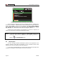
5.8
Automatic signal identification function (AUTO ID)
The PRODIG-5 (EXPLORER) allows automatically identifying TV signals,
according to the established configuration, which are presents in the channel or tuned
frequency. In order to activate this function must once press
[25] key. Specially
useful, is to combine this process with the spectrum monitoring
[13], so that after
locating the marker on the levels susceptible to contain a transmission, and activating
later the process of automatic identification in order to identify the present signal.
09/2005
Page 29
English
Table 3.- External units powering voltages.
USER’S MANUAL. PRODIG-5
FREQ:
CHANNEL:
STARTING...
TESTING FOR ANALOG
TESTING DVB-T
POWER OK
TRYING CURRENT DVB-T CONFIG.
CANCEL
Figure 8.- Signal automatic identification screen. AUTO ID.
First it recognises whether the signal is an analogue channel or a digital one. If
the channel is analogue, it determines the television standard of the signal. When the
signal is digital (DVB), it analyses for each modulation type QAM / QPSK / COFDM all
the associated parameters such as the modulation system: carriers 2k-8k, symbol
rate, code rate, etc.,. and determines the value of the signals under test.
Whenever the process detects new parameters for a channel or frequency will
create a new channel plan containing the detected information.
NOTE: In the case that is desired to explore or identify DVB-C signals will be
necessary to select previously a DVB-C standard as digital signal identifier by
means of
5.9
[22] PREFERENCES menu.
Channel plans
As much the signal automatic identification process as the exploration of the
frequency spectrum could yield the generation of new customised channel plans
relative to the usual work locations of the meter equipment.
In this way the characterisation of the band will be more fast and simple when
causing that the equipment only analyses a shorter set of channels.
Page 30
09/2005
USER’S MANUAL. PRODIG-5
Whenever a new process of exploration is activated, the PRODIG-5 analyses all
the present channels in the active channel plan, which acts as pattern channel plan
specified by means of the option CHANNEL SET from configuration measurement
menu: CONFIGURATION
[17].
English
If during exploration or automatic identification process the EXPLORER detects
new parameters for some channel or frequency a new list will be generated with the
information updated and will be saved with the same name of the original channel plan
followed by the extension: _0x. (See the following Figure).
Figure 9.- New channel plan generation process.
The user can edit the channel plan name and select the channel plans to delete
by means of MODIFY CHANNEL PLAN option from UTILITIES
[22] menu.
The EXPLORER allows directly changing the tuned channel pertaining to the active
channel plan by means of the horizontal
the channel tuning field
cursors [6]. From this way, once selected
[24] and in the TV
[10] and MEASUREMENTS
[12] operation modes is possible to check cyclically the entire active channel list.
09/2005
Page 31
USER’S MANUAL. PRODIG-5
5.10
Spectrum exploration function (EXPLORER)
The Exploration function allows exploring the full frequency band in order to
identify the analogue channels and digital presents, in agreement with the configuration
set, in the tuning band. In order to activate the function hold pressed the
until the EXPLORER screen appears.
[25] key
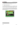
TESTING CHANNEL SET:
0
25
50
75
100%
66 DVB-T OK
67 UNIDENTIFIED
68 ANALOG: PAL BG
69 NO SIGNAL
FOUND: 12 / 101
PROCESS SUCCESSFUL
EXIT
SAVE AS:
PROMAX_01
Figure 10.- Spectrum exploration screen. EXPLORER.
Whenever the process detects new parameters for some channel, it will create a
new channel plan containing the detected information.
NOTE:
In the case that is desired to explore or identify DVB-C signals will be
necessary to select previously DVB-C standard as digital signal identifier by
means of
5.11
[22] PREFERENCES menu.
Measurements configuration
With the aim of taking the measurements of all types of signals some times could
be necessary that user enters parameters relative to particular characteristics of these
signals, whether an automatic detection has not been possible, or these parameters
differ from the standard corresponding ones.
[17] key to access to the
Press the Measurements Configuration
CONFIGURATION menu and turn the rotary selector [1] to access to parameters
whichare by the user.
Page 32
09/2005
Test Equipment Depot - 800.517.8431 - 99 Washington Street Melrose, MA 02176
FAX 781.665.0780 - TestEquipmentDepot.com
USER’S MANUAL. PRODIG-5
5.11.1 DVB-C (QAM) Digital Channel Configuration
Press the Measurements Configuration
[17] key to access to the
CONFIGURATION menu and turn the rotary selector [1] to access the QAM signals
parameters which can be defined by user and described below:
1)
Modulation
It defines the modulation type. When selecting this function and pressing the
rotary selector [1] a multiple-choice menu will appear on the screen, this menu
permits to choose one of the following modulations: 16, 32, 64, 128 and 256.
2)
Symbol Rate
When selecting this function and pressing the rotary selector [1] a multiple-choice
menu will appear on the screen, this menu permits to choose the symbol rate.
3)
Spectral inversion
If necessary, activate the Spectral inversion (On). If the spectral inversion is not
correctly selected, reception will not be correct.
» CHANNEL SET:
» SIGNAL:
English
CONFIGURATION
» SAVE AS:
CCIR_01
CCIR
DVB-C
PAL
» SYSTEM:
20
40
60
80
100
120
50Hz
FRAME RATE:
16.5 dB
FREQ:
650.00 MHz
C/N:
8.00MHz
» CHANNEL BW:
66.2 dBuV
-3 kHz
POWER:
OFF dB
»
SPECTRAL
INV:
24.7
43
MER:
CH:
6875kSymb
» SYMBOL RATE: BER:
3.4E-4
0
» MODULATIONS:
64QAM
MPEG-2
Figure 11.- Screen of mesurement configuration (QAM signals).
09/2005
Page 33
USER’S MANUAL. PRODIG-5
5.11.2 DVB-T (COFDM) Digital Channel Configuration
Press the Measurements Configuration
[17] key to access to the
CONFIGURATION menu and turn the rotary selector [1] to access the COFDM signals
parameters which can be defined by user and described below:
1)
Carriers (Number of carriers)
It defines the number of modulation carriers between 2k and 8k. To modify its
value, place the marker over the Carriers field by turning the rotary selector and
then press it: a menu will appear on the screen. Turning the rotary selector [1]
select the desired value for the Carriers parameter and finally press it again to
validate.
2)
Guard Interval
The Guard Interval parameter corresponds to the dead time between symbols,
its purpose is to permit a correct detection in multi-path situations. This parameter
is defined according to the symbol length: 1/4, 1/8, 1/16, 1/32. To modify its value,
by turning the rotary selector [1], place the marker over the Guard Interval field
and then press it : a menu with the available values will appear. Turning the rotary
selector [1] select the desired value and finally press it to validate.
3)
Channel BW (channel bandwidth)
Enables the channel bandwidth to be selected between 8 MHz, 7 MHz and 6
MHz. The selection of this parameter is essential for the correct operation of the
tuner, as it affects the frequency separation of the carriers.
4)
Spectral Inv. (spectral inversion)
This option enables spectral inversion to be applied to the input signal, though in
the majority of cases it should be in the OFF position (not inversion).
This configuration menu shows, besides the user definable COFDM signal
parameters, the value of the rest of signal parameters detected automatically:
Code Rate
Also known as Viterbi ratio, defines the ratio between the data bits
number and the total number of bits transmitted (the difference
corresponds to the number of control bits for the error detection and
recovery).
Modulations
Carriers modulation. It also defines the system noise immunity.
(QPSK, 16-QAM and 64-QAM).
Hierarchy
The DVB-T norm contemplates the possibility to make a TDT
transmission with hierarchical levels, it is to say a simultaneous
transmission of the same program with different image qualities and
noise protection levels, in order the receiver can exchange to a
signal of smaller quality when the reception conditions are not
optimal.
Page 34
09/2005
USER’S MANUAL. PRODIG-5
CONFIGURATION
» CHANNEL SET:
CCIR
» SIGNAL:
DVB-T
» SYSTEM:
PAL
FRAME
20
40RATE:
60
80
100 50Hz
120
8MHz
» CHANNEL BW:
FREQ:
650.00 MHz
C/N:
16.5 dB
1/4
» GUARD:
-3 kHz
POWER:
66.2 dBuV
8K dB
» CARRIERS:
CH:
43
MER:
24.7
OFF
» SPECTRAL INV:CBER:
3.4E-4
VBER:
<1.0E-7
1/2
CODE RATE:
0
MPEG-2
Figure 12.- Screen of mesurement configuration (COFDM signals).
Press the Measurements Configuration
[17] key to access to the
CONFIGURATION menu and turn the rotary selector [1] to access the QPSK signals
parameters which can be defined by user and described below:
1)
Symbol Rate
It is possible to choose between the following values: from 2000 to 45000 kbauds.
When selecting the option appears the current value, in order to modify it enter a
new value through keyboard when appears the data enter symbol appears on the
upper left corner screen.
2)
Code Rate
Also known as Viterbi ratio. It defines the ratio between the number of data bits
and actual transmission bits (the difference corresponds to the control bits for
error detection and correction).
It permits to choose between 1/2, 2/3, 3/4, 5/6 and 7/8.
3)
Spectral Inv
If necessary, activate the Spectral inversion (On). Reception will be bad if
spectral inversion has been incorrectly selected.
09/2005
Page 35
English
5.11.3 DVB-S (QPSK) Digital Channel Configuration
USER’S MANUAL. PRODIG-5
CONFIGURATION
» SAVE AS:
» CHANNEL SET:
» SIGNAL:
ASTRA-VL_01
ASTRA-VL
DVB-S
PAL
» SYSTEM:
20
40
60
80
100
120
50Hz
FRAME RATE:
FREQ:
1479.0 MHz
C/N:
-12.4 dB
42.00MHz
» CHANNEL BW:
--- kHz
POWER:
20.2 dBµV
OFF
»11229.0
SPECTRAL
INV:MER:
DL:
MHz
5.2 dB
3/4
» CODE 2RATE:
CH:
MHz
CBER:
3.3E-2
<3.9E-3
» SYMBOL RATE: VBER: 27500kSymb
0
CARRIER RECOVERED
Figure 13.- Screen of mesurement configuration (QPSK signals).
IMPORTANT REMARK
DVB channels tuning may require an adjusting process. It is recommended to follow
next procedure:
1.
From the spectrum analyser mode
frequency.
[13], tune the channel at its central
2.
Switch to Measurements mode
3.
If in the lower line of the screen does not appear MPEG-2 message (and
consequently BER is unacceptable), by turning the rotary selector deviate the
tuning frequency until MPEG-2 message appears. Finally tune channel again
to minimize the frequency deviation which optimizes the BER and therefore
minimize the BER.
[12], measurement selection.
If it is not possible to detect any MPEG-2 channel, make sure that digital signal
parameters are correctly defined.
Page 36
09/2005
USER’S MANUAL. PRODIG-5
5.12
Selecting the Measurements
The types of measurements available depend on the operating band (terrestrial or
satellite) and the type of signals (analogue or digital).
Terrestrial band - Analogue channels:
Level
Level measurement of the currently tuned carrier.
Video / Audio
Video carrier to audio carrier ratio.
C/N
Ratio between the modulated signal power and the equivalent
noise power for a same bandwidth.
Channel power
Channel power is measured assuming that power spectral
density is uniform throughout channel bandwidth.
To measure it correctly it is indispensable to define the
Channel BW.
C/N
Out-channel measurement. Noise level is measured at fnoise=
ftuning ± ½*Channel BW. To measure it correctly digital
channel must be tuned at its central frequency.
MER
Modulation error ratio.
CBER
BER measurement (Bit error rate) for the digital signal before
error correction (BER before FEC).
VBER
BER measurement (Bit error rate) for the digital signal after
error correction (BER after Viterbi).
English
Terrestrial band - Digital channels (DVB-C and DVB-T):
Satellite band - Analogue channels
Level
Level measurement of the currently tuned carrier.
C/N
Ratio between the modulated signal power and the equivalent
noise power for a same bandwidth.
09/2005
Page 37
Test Equipment Depot - 800.517.8431 - 99 Washington Street Melrose, MA 02176
FAX 781.665.0780 - TestEquipmentDepot.com
USER’S MANUAL. PRODIG-5
Satellite band - Digital channels (DVB-S):
Channel Power
Automatic method.
C/N
Ratio between the modulated signal power and the equivalent
noise power for a same bandwidth.
MER
Modulation error ratio.
CBER
BER measurement (Bit error rate) for the digital signal before
error correction (BER before FEC).
VBER
BER measurement (Bit error rate) for the digital signal after
error correction (BER after Viterbi).
[12] key. On the monitor
In order to change the measurement mode press
will appear cyclically all the measures available for the tuned signal.
5.12.1 Analogue TV: Measuring the Video Carrier Level
In the measurement mode of analogue signals, the PRODIG-5 (EXPLORER),
monitor can work as an analogue indicator of level representing the signal present in
the input.
[12] key, it will appear a
In order to change the measurement mode press
screen like the following one:
0
FREQ:
CH:
20
40
60
168.25 MHz
S10 MHz
80
100
» LEVEL:
C/N:
V/A:
120
79.2 dBµV
40.1 dB
16.2 dB
Figure 14.- Analogue signal level measurement in terrestrial band.
Page 38
09/2005
USER’S MANUAL. PRODIG-5
Turn the rotary selector [1] to change the tuning channel/frequency. Press the
[12] key to select the type of measurement to visualise on the monitor.
The available types of measurements are:
LEVEL:
Level indication on the upper part of the screen (analogue
bar).
C/N:
Carrier/Noise ratio measurement.
V/A:
Video/Audio ratio measurement.
WARNING
When at the RF input appear an important number of carriers with a high level the
tuning circuit may become out of control, giving as a result wrong level measurements.
To be able to determinate the equivalent level of a carrier group (with similar levels) at
the RF input, it is possible to use the expression:
English
Lt=L + 10 log N
Lt: equivalent total level
L: average level of the carriers group
N: number of carriers
So, if there are ten carriers with a level around 90 dBµV, their equivalent level will be:
90 dBµV + 10 log 10 = 100 dBµV
Observe that in this case, loss of tuning by overload of the RF input may occur besides
other effects such as tuner saturation and generation of intermodulation products that
may mask the spectrum visualization.
09/2005
Page 39
USER’S MANUAL. PRODIG-5
5.12.2 Analogue TV: Measuring the Video / Audio ratio (V/A)
In the Audio/Video measurement mode, on the screen appears the following
information:
0
FREQ:
CH:
10
168.25 MHz
S10 MHz
20
30
LEVEL:
C/N:
» V/A:
40
79.2 dBµV
40.1 dB
16.2 dB
Figure 15.- Measurement of the video/audio rate
In addition to the video carrier / audio carrier level ratio (16.2 dB in previous
figure) it also shows the frequency or channel, depending on the tuning mode selected,
and the Carrier/Noise ratio.
5.12.3 Analogue/Digital TV: Measuring the Carrier / Noise ratio (C/N)
The PRODIG-5 (EXPLORER) carries out C/N ratio measurement in four different
ways, according to the carrier type and the used band:
A)
Terrestrial band, analogue carrier
Carrier level is measured using a quasi-peak detector (230 kHz BW). Noise level
is measured with an average detector and corrected to refer it to channel
equivalent noise bandwidth (according to the definition of the selected standard).
B)
Terrestrial band, digital carrier
Both measurements are done with an average detector (230 kHz) and the same
corrections are introduced on them (bandwidth corrections).
C)
Satellite band, analogue carrier
Carrier level is measured using a quasi-peak detector (4 MHz BW). Noise level is
measured with an average detector (230 kHz) and corrected to refer it to channel
bandwidth.
Page 40
09/2005
USER’S MANUAL. PRODIG-5
D)
Satellite band, digital carrier
Equivalent to case B but now using the 4 MHz BW filter.
On selecting the Carrier / Noise measurement mode the screen displays the
following information:
0
FREQ:
CH:
10
168.25 MHz
S10 MHz
20
30
LEVEL:
» C/N:
V/A:
40
79.2 dBµV
40.1 dB
16.2 dB
As well as the video carrier / noise level ratio (40.1 dB in previous figure), the
frequency or channel (depending on the tuning mode selected) and the level of the
video carrier and video/audio ratio are also shown.
When measuring channels in the satellite band or digital channels, to measure
the C/N ratio correctly, the bandwidth of the channel must be defined previously, using
the Channel BW option on the Measurements Configuration menu that appears
when pressing
[17] key.
IMPORTANT REMARK
To measure digital channels C/N ratio it is indispensable to tune channel at its central
frequency.
In the case of the presence of adjacent digital channels, these could mask the noise
level measurement.
09/2005
Page 41
English
Figure 16.- Carrier-to-noise ratio measurement (C/N).
USER’S MANUAL. PRODIG-5
5.12.4 Digital TV: Measuring the Power of Digital Channels
The PRODIG-5 (EXPLORER) measures digital channel power in the measurement
filter bandwidth and estimates total channel power assuming that spectral density is
uniform throughout channel bandwidth.
On selecting the CHANNEL POWER measurement mode, the screen displays
the following information:
0
20
FREQ:
CH:
40
60
650.00 MHz
-3 kHz
43
80
100
120
C/N:
16.5 dB
» POWER: 66.2 dBuV
MER:
24.7 dB
CBER:
3.4E-4
VBER:
<1.0E-7
MPEG-2
Figure 17.- Digital channel power measurement.
In addition to the power of the digital channel (66.2 dBµV in previous figure) this
also shows the tuning frequency or channel, depending on the tuning mode selected,
and the offset frequency to calculate the digital channel power.
For the power measurement of a digital channel to be correct it is essential to
have previously defined the channel bandwidth using the Channel BW option, in the
Measurements Configuration menu that appears when pressing
[17] key.
5.12.5 Digital TV: Measuring BER
The PRODIG-5 (EXPLORER) offers three ways to measure the error rate (BER) of
digital signals depending on the type of used modulation.
To select the BER measurement mode:
1)
Select digital signals Measurements Configuration pressing
Page 42
[17] key.
09/2005
Test Equipment Depot - 800.517.8431 - 99 Washington Street Melrose, MA 02176
FAX 781.665.0780 - TestEquipmentDepot.com
USER’S MANUAL. PRODIG-5
2)
Select by means of Signal option from CONFIGURATION menu: DVB-C for the
measurement of QAM modulated signals, DVB-T for the measurement of
COFDM modulated signals or DVB-S for the measurement of QPSK modulated
signals. Available frequency ranges are:
DVB-C (QAM) signals
DVB-T (COFDM) signals
DVB-S (QPSK) signals
45 MHz to 865 MHz
45 MHz to 865 MHz
950 MHz to 2150 MHz
3)
Enter the parameters relative to the digital signal which appear in the
measurement CONFIGURATION menu, as described previously (see section
“5.11 Measurements Configuration”).
4)
Select the option to exit from measurements CONFIGURATION menu.
5.12.5.1
DVB-C signals
BER, press the
[12] key until the BER measurement display appears.
In the BER measurement mode, the monitor will show a display like the following
one:
-6
FREQ:
CH:
-5
-4
650.00 MHz
-3 kHz
43
-3
C/N:
POWER:
MER:
» BER:
-2
-1
16.5 dB
66.2 dBuV
24.7 dB
3.4E-4
MPEG-2
Figure 18.- Screen of BER measurement of QAM signals.
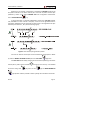
The BER measurement before error correction is shown: BER before FEC
(Forward Error Correction).
09/2005
Page 43
English
Once determined the parameters of QAM signal, it will be possible to measure
USER’S MANUAL. PRODIG-5
In a digital reception system for cable signals, after the QAM demodulator an
error correction method called Reed-Solomon is applied (see following Figure).
Obviously, the error rate after the corrector is lower to the error rate at the QAM
decoder output. This is the reason because this screen provides the BER measurement
before FEC (Forward Error Correction).
Figure 19.- Digital reception system via cable.
The BER measurement is provided in scientific notation (i.e. 1.0 E-5 means
-5
1.0x10 that is to say one wrong bit of every 100,000) and through an analogue bar (as
its length is smaller the signal quality will be better). The analogue representation is
done on a logarithmic scale (not linear).
With the aim to have a reference about the signal quality, it is considered that a
system has a good quality when it decodes less than one non-correctable error for
every transmission hour. This border is known as QEF (Quasi-Error-Free) and it
-4
corresponds approximately to a BER before FEC of 2.0E-4 BER (2.0x10 , that is to say
two incorrect bits of every 10,000). This value is marked on the measurement bar of the
BER and therefore, BER for acceptable signals must be at the left side of this mark.
Below the BER analogue bar it is shown the tuned frequency (or channel) and the
frequency deviation in kHz between the tuned frequency and the one which optimizes
the BER (i.e. 800.00 MHz + 1.2 kHz). This deviation must be adjusted specially from the
C/N measurement in satellite band, by tuning again the channel in frequency
mode
[24], to the lower reachable value.
5.12.5.2
DVB-T signals
Once determined the parameters of COFDM signal, it will be possible to measure
BER.
Two types of measurements appear:
Following is shown the BER measurement before the error corrections: BER
before the FEC: CBER.
Page 44
09/2005
USER’S MANUAL. PRODIG-5
-6
-5
FREQ:
CH:
-4
-3
650.00 MHz
-3 kHz
43
-2
C/N:
POWER:
MER:
» CBER:
VBER:
-1
16.5 dB
66.2 dBuV
24.7 dB
3.4E-4
<1.0E-7
MPEG-2
In a reception system of terrestrial digital signal, after the COFDM decoder two
error correction methods are applied. Obviously, each time we apply an error corrector
to the digital signal, the error rate changes, therefore if we measure the error rate at the
output of the COFDM demodulator, at the output of the Viterbi decoder, and at the
output of the Reed-Solomon decoder, we obtain nothing more than different error rates.
The PRODIG-5 (EXPLORER) provides the BER after Viterbi (VBER).
Figure 21.- COFDM reception system.
-7
FREQ:
CH:
-6
-5
QEF
650.00 MHz
-3 kHz
43
-3
C/N:
POWER:
MER:
CBER:
» VBER:
-2
-1
16.5 dB
66.2 dBuV
24.7 dB
3.4E-4
<1.0E-7
MPEG-2
Figure 22.- Screen of BER measurement (COFDM signals). VBER.
09/2005
Page 45
English
Figure 20.- Screen of CBER measurement (COFDM signals).
USER’S MANUAL. PRODIG-5
The BER measurement is provided in scientific notation (i.e. 3.1 E-7 means
-7
3.1x10 , that is to say 3.1 average value of wrong bits of each 10000000) and through
a graphic bar (as its length is smaller the signal quality will be better). The analogue
representation is done on a logarithmic scale (not linear), that is to say, the bar divisions
correspond to the exponent of the measurement.
With the aim to have a reference about the signal quality, it is considered that a
system has a good quality when it decodes less than one non-correctable error for
every transmission hour. This border is known as QEF (Quasi-Error-Free) and it
-4
corresponds approximately to a BER after Viterbi of 2.0E-4 BER (2.0x10 , that is to say
2 wrong bits of each 10000). This value is marked on the measurement bar of the BER
and therefore, BER for acceptable signals must be at the left side of this mark.
Finally it is shown a status line with information about the detected signal. The
possible messages that can appear and its meaning are showing the following list. The
messages are exposed from less to more fulfilment of the MPEG-2 standard:
No signal received
No signal has been detected.
Timing recovered
Only it is possible to recuperate the symbol time.
AFC in lock
The system automatic frequency control can identify and lock a digital
transmission (TDT) but its parameters can not be obtained. It can be due to a
transitory situation previous to the TPS identification (Transmission Parameter
Signalling) or well to a TDT transmission with an insufficient C/N ratio.
TPS in lock
The TPS (Transmission Parameter Signalling) are decoded. The TPS are carriers
(17 in the 2k system and 68 in the 8k system) modulated in DBPSK, containing
information related to the transmission, modulation and codification: Modulation
type (QPSK, 16-QAM, 64-QAM), Hierarchy, Guard Interval, Viterbi Code Rate,
Transmission mode (2k or 8k) and Number of the received frame.
MPEG-2
Correct detection of a MPEG-2 signal.
5.12.5.3
DVB-S signals
Once determined the parameters of QPSK signal, it will be possible to measure
BER. Following is shown the BER measurement before the error corrections: BER
before the FEC: CBER.
Page 46
09/2005
USER’S MANUAL. PRODIG-5
-6
-5
FREQ:
-4
1479.0
--11229.0
2
DL:
CH:
-3
MHz
kHz
MHz
MHz
C/N:
POWER:
MER:
» CBER:
VBER:
-2
-1
-12.4 dB
20.2 dBµV
5.2 dB
3.3E-2
<3.9E-3
MPEG-2
In a digital reception system for satellite signals, after the QPSK decoder two
different correction methods are applied (see following Figure). Obviously, each time we
apply an error corrector to a digital signal, the error rate changes, therefore if we
measure in a digital satellite television system, for example, the error rate at the output
of the QPSK demodulator, at the output of the Viterbi decoder, and at the output of the
Reed-Solomon decoder, we obtain nothing more than different error rates. This is the
reason because the BER measurement is provided before FEC, after Viterbi (VBER).
English
Figure 23.- Screen of CBER measurement (QPSK signals).
Figure 24.- Digital reception system via satellite.
-8
-7
FREQ:
-6
1479.0
--11229.0
2
DL:
CH:
-5
MHz
kHz
MHz
MHz
QEF
C/N:
POWER:
MER:
CBER:
» VBER:
-4
-3
-12.4 dB
20.2 dBµV
5.2 dB
3.3E-2
<3.9E-3
MPEG-2
Figure 25.- Screen of VBER measurement (QPSK signals).
09/2005
Page 47
Test Equipment Depot - 800.517.8431 - 99 Washington Street Melrose, MA 02176
FAX 781.665.0780 - TestEquipmentDepot.com
USER’S MANUAL. PRODIG-5
The BER measurement is provided in scientific notation (i.e. 2.0 E-3 means
-3
2.0x10 , that is to say two incorrect bits of every 1,000) and through an analogue bar
(as its length is smaller the signal quality will be better). The analogue representation is
done on a logarithmic scale (not linear).
With the aim to have a reference about the signal quality, it is considered that a
system has a good quality when it decodes less than one non-correctable error for
every transmission hour. This border is known as QEF (Quasi-Error-Free) and it
-4
corresponds approximately to a BER after Viterbi of 2.0E-4 BER (2.0x10 ). This value
is marked on the measurement bar of the BER after Viterbi and therefore, BER for
acceptable signals must be at the left side of this mark.
Next it is shown the tuning frequency and the frequency deviation in MHz
between the tuned frequency and the one which optimizes the BER (i.e. Freq: 1777.0
+ 1.2 MHz).
Finally it is shown a status line with information about the detected signal. The
possible messages that can appear and its meaning are shown in the following list. The
messages are exposed from less to more fulfilment of the MPEG-2 standard:
No signal received
Any signal has been detected.
Signal received
A signal is detected but it can not be decoded.
Carrier recovered
A digital carrier has been detected but it can not be decoded.
Viterbi synchronized
A digital carrier has been detected and the Viterbi algorithm is synchronized, but
too many frames arrive with non correctable errors. It is not possible to quantify
the BER.
MPEG-2
Correct detection of a MPEG-2 signal.
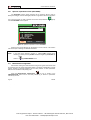
5.12.6 Digital TV: Measuring MER
Once determined the suitable parameters for COFDM, QAM or QPSK signal
reception, it will be possible to measure MER, press
MER measurement screen.
Page 48
[12] key until it appears the
09/2005
USER’S MANUAL. PRODIG-5
0
FREQ:
CH:
10
20
650.00 MHz
-3 kHz
43
30
C/N:
POWER:
» MER:
CBER:
VBER:
40
16.5 dB
66.2 dBuV
24.7 dB
3.4E-4
<1.0E-7
MPEG-2
Figure 26.- Screen of MER measurement of DVB-T (COFDM) signals.
First of all, you will see the modulation error ratio measurement: MER.
Analogue and digital carriers are very different in terms of signal contents and
power distribution over the channel. They, therefore, need to be measured differently.
The modulation error ratio (MER), used in digital systems is similar to the Signal/Noise
(S/N) ratio in analogue systems.
MER represents the relation between the average power of DVB signal and the
average power of noise present in the constellation of the signals.
By example, QAM 64 demodulators require a MER greater than 23 dB to work.
Though it is preferable to have at least a 3 or 4 dB margin to compensate for any
possible degradation of the system. While QAM 256 demodulators require an MER
greater than 28 dB with margins of al least 3 dB. Normally, the maximum MER value
seen in portable analysers is of approximately 34 dB.
Finally it is shown a status line, which displays information about the detected
signal. The possible messages that can appear and its meaning are shown in the
following list. The messages are exposed from less to more fulfilment of the MPEG-2
standard:
No signal received
Any signal has been detected.
Signal received
A signal is detected but it can not be decoded.
Carrier recovered
A digital carrier has been detected but it can not be decoded.
MPEG-2
Correct detection of a MPEG-2 signal.
09/2005
Page 49
USER’S MANUAL. PRODIG-5
5.13
Spectrum Analyser
The Spectrum Analyser mode allows the user to discover the signals present in
the frequency band in quickly and easily and to make measurements at the same time.
[13] key. The monitor will show a picture like the one described
To select it press
in the next figure.
FREQ: 650.00 MHz
POWER: 65.6 dBuV
70
60
50
40
30
CH:43
SPAN : 32 MHz
Figure 27.- Spectrum analyser mode.
The horizontal lines define the signal level, the broken lines being separated a
distance equals to 10 dB. The level of the top line (70 dBµV in previous figure), named
[6] keys between a
Reference Level, can be altered using the vertical cursors
range of 60 dBµV to 130 dBµV by steps of 10 dB (from 70 dBµV to 130 dBµV in satellite
band).
The signal level for each frequency is displayed vertically, the lower frequencies
appear at the left of the screen and the higher ones at the right. The amplitude of the
lobes is calibrated. In the example in previous figure the noise level is at around 25
dBµV and the lobe with the highest signal level (third from the right) is at 70 dBµV.
The frequency range displayed (called span from hereon) can also be altered
[6] keys. Therefore enables selecting the displayed
using the horizontal cursors
screen frequency range in Spectrum Analyser mode between Full (the entire band),
500 MHz, 200 MHz, 100 MHz, 50 MHz, 32 MHz, 16 MH and 8 MHz (the latter one only
in terrestrial bands).
A vertical broken line, called marker, appears on the spectrum display to identify
the tuned frequency.
Page 50
09/2005
USER’S MANUAL. PRODIG-5
One of the applications of the PRODIG-5 operating as Spectrum Analyser is in
the search for the best orientation and position of the receiving antenna. This is
particularly important in UHF. Because such frequencies are involved, with wavelengths
ranging from 35 cm to 65 cm, if the antenna is shifted only a few centimetres, the
relationship between the picture, chrominance and sound carrier frequencies change,
affecting the quality of the picture in the receiver.
If there is an excess of sound carrier, tearing or 'moiré' may appear on the screen
due to the frequency beats between the sound, chrominance and the picture
frequencies.
If there is a chrominance carrier defect, then the television colour amplifier must
function at maximum gain, which could result in noise appearing all over the television
screen with points of colour that disappear when the saturation control is reduced; in an
extreme case, loss of colour may occur.
5.13.1 Markers
selector [1] as well in channel as in frequency tuning mode
[24].
When monitoring a digital signal spectrum also appears two additional markers in
white colour, which indicate the bandwidth of the digital channel (See previous Figure).
5.14
TV Operating Mode
When pressing the
(EXPLORER) accedes to the
[2] key from any mode of operation the PRODIG-5
TV mode, and tries to demodules on the monitor the
currently tuned video signal.
In the monitor will appear the TV picture with a window on the lower part to show,
for five seconds, in the case that the signal is analogue, the channel number, the
frequency, the active canalization, the colour system and the TV standard.
If the signal is digital it shows, for about fifteen seconds, the following parameters:
channel number, frequency, active channel plan, type of DVB signal, service, network,
video program identifier (VPID) and audio program identifier (APID).
09/2005
Page 51
English
(Only in Spectrum Analyser mode). The marker in red colour indicates the central
frequency or tuning frequency, which can be moved by means of turning the rotary
USER’S MANUAL. PRODIG-5
After few seconds only the TV image appears on screen. If the transmission is not
codified on the lower right corner a (FREE) indication is showed or otherwise states
(COD). Also the standard MPEG-2 profile is indicated which determines the
compression rate for the digital service decodified, the level of image resolution (4:3),
the resolution (rows x columns) for received video and the picture refreshment
frequency rate. The information window previously described will appear whenever the
rotary selector is pressed again [1].
CHANNEL:
S10
CCIR-FR2
FR: 168.25 MHz
50 Hz
PAL BG
Figure 28.- Analogue channel monitoring.
When a digital channel is decodified, once the Table of Services SDT (Service
Description Table) acquisition is completed, is possible to accede to the list of
services contained in the Table.
[6], on the
For it place the field selector, by means of the vertical cursors
field of the active service (e.g. Veo TV in the following figure) and later press the rotary
selector [1].
The DVB SERVICES menu will appear then with the services available in the
[6] or turn the rotary selector [1] and
digital Multiplex. Move the vertical cursors
press it to select the service to visualise on screen.
Page 52
09/2005
Test Equipment Depot - 800.517.8431 - 99 Washington Street Melrose, MA 02176
FAX 781.665.0780 - TestEquipmentDepot.com
USER’S MANUAL. PRODIG-5
DVB SERVICES
DTV
VPID: 301
APID: 302
ANTENA 3-ANTEN
CANAL+ - SOGECABL MP@ML
1024x768
CHANNEL:
66Veo TV
4:3 50 Hz
CCIR
EXIT MHz
834.00
Component
DVB-T
TVE-1 Televisi
TVE-2 Televisi
Veo TV
NETW.: TV Net
SID: 1536
NID: 12547
(FREE)
Figure 29.- Digital channel monitoring.
[6] once has selected the field of the service from information window of
cursors
the currently tuned channel.
5.15
Antenna Alignment Function
It allows executing the function Antenna Alignment to align antennas using a
faster sweep without display of numerical measures. The display appears divided in two
parts, the left one shows the spectrum of the signals detected in the band and on the
right an analogue bar represents the level of signal corresponding to the tuned
frequency or channel.
FR:
100
1856.4 MHz
90
80
70
60
CH:
61
SPAN:
50 MHz
Figure 30.- Utility for antenna alignment
09/2005
Page 53
English
Also is possible to change the active service directly acting through the horizontal
USER’S MANUAL. PRODIG-5
Simultaneously the instrument emits by means of the loudspeaker an acoustic
tone which varies according to the level of received signal.
5.16
DiSEqC Command Generator
DiSEqC4 ('Digital Satellite Equipment Control') is a communication protocol
between the satellite receiver and the accessories of the installation (switches, LNBs,
etc.) proposed by Eutelsat, with the aim to standardize the diversity of switching
protocols (13 - 18 V, 22 kHz) and to satisfy the demands of the digital TV installations.
In order to define and/or to send a sequence of DiSEqC commands, press the
DiSEqC key [21] on frontal panel. It allows to define the satellite band configuration
parameters and select through SEND function one of the eight predefined programs
which execute basic functions to control an universal switch with two or four inputs, by
means of the rotary selector [1].
DiSEqC
» POLARIZATION
» SAT BAND
» SEND
20 EXIT
40
0
FREQ:
DL:
CH:
VERTICAL
HIGH
POSITION A/B
60
1479.0 MHz
11229.0 MHz
2 MHz
80
LEVEL:
C/N:
100
A
120
30.0 dBµV
7.6 dB
Figure 31.- DiSEqC command screen.
4 DiSEqCTM is a trademark of EUTELSAT.
Page 54
09/2005
USER’S MANUAL. PRODIG-5
6 DESCRIPTION OF THE INPUTS AND OUTPUTS
6.1
RF input
The RF input is through the RF
[37] connector on the side panel. The
peak signal level should never exceed 130 dBµV.
6.2
RS-232C serial port
The PRODIG-5 (EXPLORER) incorporates an RS-232C serial port for diagnosis,
setup and calibration processes. The signals in this connector are described in Table 4.
5
4
3
9
8
7
2
6
English
1
Figure 32.- RS-232C connector. External view.
PIN No.
1
2
3
4
5
6
7
8
9
SIGNAL
Carrier detect
Data Receive (RxD)
Data Transmit (TxD)
Data Terminal Ready (DTR)
Ground (GND)
Data Set Ready (DSR)
Request to Send (RTS)
Clear to Send (CTS)
Ring Indicator
CHARACTERISTICS
(not connected)
(not connected)
(not connected)
(not connected)
Table 4.- Description of the RS-232C connector.
09/2005
Page 55
USER’S MANUAL. PRODIG-5
6.3
Scart (DIN EN 50049)
Figure 33.- Scart socket (external view).
Also known as PERITEL connector (in conformity with standard NF-C92250).
The signals in this connector are the following:
PIN number
1
2
3
4
5
6
7
8
9
10
11
12
13
14
15
16
17
18
19
20
21
SIGNAL
Right channel audio output
Right channel audio input
Left channel audio output
Audio grounding
Blue grounding (B)
Left channel audio input
Blue output (B)
Switching voltage
Green grounding (G)
Digital bus interface
Green output (G)
Digital bus interface
Red grounding (R)
Digital bus reserved
Red output (R)
Blanked signal
Composite video grounding
Blanked return
Composite video output
Video input
Connector shield grounding
CHARACTERISTICS
(not connected)
(not connected)
(not connected)
(not connected)
(not connected)
Table 5.- Description of the Scart.
Page 56
09/2005
USER’S MANUAL. PRODIG-5
7 MAINTENANCE
7.1
Considerations about the Screen.
This paragraph offers key considerations regarding the use of the colour screen,
taken from the specifications of the manufacturer.
In the TFT display, the user may find pixels that do not light up or pixels that are
permanently lit. This should not be regarded as a defect in the TFT. In accordance with
the manufacturer quality standard, 9 pixels with these characteristics are considered
admissible.
Pixels which are not detected when the distance from the surface of the TFT
screen to the human eye is greater than 35 cm, with a viewing angle of 90º between the
eye and the screen should not be considered manufacturing defects either.
7.2
Cleaning Recommendations
CAUTION
To clean the cover, take care the instrument is disconnected.
English
It is advisable a viewing angle of 15º in the 6.00 o’clock direction in orden to
obtain the optimum visualization of the screen.
CAUTION
Do not use scented hydrocarbons or chlorized solvents. Such products may attack the
plastics used in the construction of the cover.
The cover should be cleaned by means of a light solution of detergent and
water applied with a soft cloth.
Dry thoroughly before using the system again.
CAUTION
Do not use for the cleaning of the front panel and particularly the viewfinders, alcohol or
its derivatives, these products can attack the mechanical properties of the materials and
diminish their useful time of life.
09/2005
Page 57
Test Equipment Depot - 800.517.8431 - 99 Washington Street Melrose, MA 02176
FAX 781.665.0780 - TestEquipmentDepot.com