1
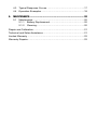
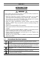
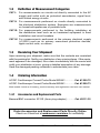
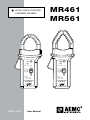
AC/DC OSCILLOSCOPE CURRENT PROBES MR461 MR561 OL OL ON ON 600V CAT III - 600A 600V CAT III - 1500A 60A 150A 600A 1500A OFF OFF ! OUTPUT: 600A: 1 mV/A 60A: 10 mV/A ENGLISH ! OUTPUT: 1500A: 1 mV/A 150A: 10 mV/A AC/DC CURRENT PROBE AC/DC CURRENT PROBE Model MR 461 Model MR 561 User Manual Statement of Compliance Chauvin Arnoux®, Inc. d.b.a. AEMC® Instruments certifies that this instrument has been calibrated using standards and instruments traceable to international standards. We guarantee that at the time of shipping your instrument has met its published specifications. An NIST traceable certificate may be requested at the time of purchase, or obtained by returning the instrument to our repair and calibration facility, for a nominal charge. The recommended calibration interval for this instrument is 12 months and begins on the date of receipt by the customer. For recalibration, please use our calibration services. Refer to our repair and calibration section at www.aemc.com. Serial #: _________________________________ Catalog #: 1200.72 / 1200.73 Model #: MR461/ MR561 Please fill in the appropriate date as indicated: Date Received: __________________________________ Date Calibration Due: ________________________ Chauvin Arnoux®, Inc. d.b.a AEMC® Instruments www.aemc.com Table of Contents 1.INTRODUCTION................................................................................ 3 1.1 1.2 1.3 1.4 International Electrical Symbols.................................................3 Definition of Measurement Categories......................................4 Receiving Your Shipment...........................................................4 Ordering Information..................................................................4 1.4.1 Accessories and Replacement Parts.............................4 2. PRODUCT FEATURES....................................................................... 5 2.1 2.2 2.3 2.4 Description.................................................................................5 MR461 Features........................................................................6 MR561 Features........................................................................7 Instrument Display Compatibility...............................................8 3.SPECIFICATIONS............................................................................. 9 3.1 Reference Conditions................................................................9 3.2 MR461 Specifications................................................................9 3.2.1Electrical........................................................................9 3.2.2 Mechanical...................................................................10 3.3 MR561 Specifications..............................................................10 3.3.1Electrical......................................................................10 3.3.2 Mechanical................................................................... 11 3.4 Common Specifications (MR461 & MR561)............................ 11 3.4.1Electrical...................................................................... 11 3.4.2 Mechanical...................................................................12 3.4.3 Safety...........................................................................13 4.OPERATION................................................................................... 14 4.1 Making Measurements............................................................14 4.1.1 DC Measurement.........................................................14 4.1.2 AC Measurement.........................................................15 4.1.3 Indicator Lights: Green LED........................................15 4.1.4 Making Measurements with the Connector.................15 4.1.5 Auto-Off........................................................................16 4.2 Tips For Getting the Best Accuracy.........................................16 4.3 Typical Response Curves........................................................17 4.4 Operation Examples................................................................18 5.MAINTENANCE.............................................................................. 20 5.1 Maintenance............................................................................20 5.1.1 Battery Replacement...................................................20 5.1.2 Cleaning.......................................................................20 Repair and Calibration............................................................................21 Technical and Sales Assistance.............................................................21 Limited Warranty....................................................................................22 Warranty Repairs....................................................................................22 CHAPTER 1 INTRODUCTION WARNING These safety warnings are provided to ensure the safety of personnel and proper operation of the instrument. •Read this instruction manual completely and follow all the safety information before attempting to use or service this instrument. •Use caution on any circuit: Potentially high voltages and currents may be present and may pose a shock hazard. •Read the safety specifications section before using the Model MR461 or MR561. Never exceed the maximum working voltage ratings given. •Safety is the responsibility of the operator! •Never open the back of the instrument while connected to any circuit or input. •ALWAYS connect the Model MR461 or MR561 to the display device before clamping the probe onto the sample under test. •Always inspect the instrument and lead prior to use. Replace any defective parts immediately. •NEVER use the Model MR461 or MR561 on electrical conductors rated above 600V. 1.1 International Electrical Symbols This symbol signifies that the instrument is protected by double or reinforced insulation. This symbol on the instrument indicates a WARNING and that the operator must refer to the user manual for instructions before operating the instrument. In this manual, the symbol preceding instructions indicates that if the instructions are not followed, bodily injury, installation/sample and product damage may result. Risk of electric shock. The voltage at the parts marked with this symbol may be dangerous. This symbol refers to a type A current sensor. This symbol signifies that application around and removal from HAZARDOUS LIVE conductors is permitted. In conformity with WEEE 2002/96/EC AC/DC Current Probe Models MR461 and MR561 3 1.2 Definition of Measurement Categories CAT I: For measurements on circuits not directly connected to the AC supply wall outlet such as protected secondaries, signal level, and limited energy circuits. CAT II: For measurements performed on circuits directly connected to the electrical distribution system. Examples are measurements on household appliances or portable tools. CAT III: For measurements performed in the building installation at the distribution level such as on hardwired equipment in fixed installation and circuit breakers. CAT IV: For measurements performed at the primary electrical supply (<1000V) such as on primary overcurrent protection devices, ripple control units, or meters. 1.3 Receiving Your Shipment Upon receiving your shipment, make sure that the contents are consistent with the packing list. Notify your distributor of any missing items. If the equipment appears to be damaged, file a claim immediately with the carrier and notify your distributor at once, giving a detailed description of any damage. Save the damaged packing container to substantiate your claim. 1.4 Ordering Information AC/DC Oscilloscope Current Probe Model MR461.............. Cat. #1200.72 AC/DC Oscilloscope Current Probe Model MR561.............. Cat. #1200.73 Both models include a 9V battery, product warranty and registration card and user manual. 1.4.1 Accessories and Replacement Parts Banana/BNC connector XF-SS (4mm plug adaptor)............ Cat. #2111.32 Order Accessories and Replacement Parts Directly Online Check our Storefront at www.aemc.com/store for availability 4 AC/DC Current Probe Models MR461 and MR561 CHAPTER 2 PRODUCT FEATURES 2.1Description The MR probes are a line of professional AC/DC current probes. They are designed to the latest safety and performance standards. Two different hook-shaped jaws are offered, both permitting the user to “pry” into or “hook” onto cables (will accept 2 x 500 MCM) or small bus bars. The MR series uses Hall effect technology. The electronics and batteries are self-contained in the handles. The output of the AC/DC probes is 1mV/ A and 10mV/A. An auto zero push button ensures rapid and stable zeroing. There is no output filtering – True RMS with DC components is possible. Phase shift is excellent, making the MR series well suited for power and power quality applications. Model MR461 is a portable 400AAC (600A peak), 600ADC current probe. The unit has proportional mV output for direct readings on handheld and bench top oscilloscopes. Model MR561 is a portable 1000AAC (1500A peak), 1500ADC current probe that accurately measures AC or DC current waveforms using Hall effect technology. AC/DC Current Probe Models MR461 and MR561 5 2.2 MR461 Features 1 Ø = 1.18" (30mm) Cable max 2 Ø = 0.95" (24mm) Dual Cable max 3 9 4 OL ON 8 600V CAT III - 600A 60A 600A 7 OFF 5 ! OUTPUT: 600A: 1 mV/A 60A: 10 mV/A AC/DC CURRENT PROBE Model MR 461 6 Figure 1 1. Jaws 8. Green light (on when battery voltage ≥ 6.5V) 2. Conductor 3. Protective non-slip guard 4. Zero adjustment button 9. Red light (overrange and incorrect zero adjustment) 5. BNC Connector 6. Coaxial cable 6.5 ft (2m) 7. Three-position range selection switch: • 60A (10mV/A) • 600A (1mV/A) • On/Off 6 AC/DC Current Probe Models MR461 and MR561 2.3 MR561 Features Ø = 1.6" (42 mm) Cable max 1 1.96 x 0.19" (50 x 5 mm) Dual Bus Bar max 2 Ø = 0.98" (25 mm) Dual Cable max 3 9 4 OL ON 8 600V CAT III - 1500A 150A 7 1500A OFF 5 ! OUTPUT: 1500A: 1 mV/A 150A: 10 mV/A AC/DC CURRENT PROBE Model MR 561 6 Figure 2 1. Jaws 2. Conductor 3. Protective non-slip guard 4. Zero adjustment button 8. Green light (on when battery voltage ≥ 6.5V) 9. Red light (overrange and incorrect zero adjustment) 5. BNC Connector 6. Coaxial cable 6.5 ft (2m) 7. Three-position range selection switch: • 150A (10mV/A) • 1500A (1mV/A) • On/Off AC/DC Current Probe Models MR461 and MR561 7 2.4 Instrument Display Compatibility The Model MR461 and MR561 current probes are compatible with any hand-held and bench top oscilloscope, which have the following features: • BNC input • Range and resolution capable of displaying 1mV of output per amp of measured current • Instrument accuracy of 0.3% or better to take full advantage of the probe accuracy • Input impedance of 1MΩ/100 pF or greater When the probe is making a measurement, the current-carrying conductor is not broken and remains electrically isolated from the probe output. As a result, the probe output common may be either floated (isolated) or grounded. Warning: User Safety Always use an oscilloscope, voltmeter or other displaying device, appropriately rated for safety to the voltage of the sample being tested. 8 AC/DC Current Probe Models MR461 and MR561 CHAPTER 3 SPECIFICATIONS 3.1 Reference Conditions 18° to 28°C, 20 to 75% RH, external magnetic field < 40 A/m, no external current carrying conductor, test sample centered, 1MΩ ≤100pF load, zero adjustment prior to measurement (DC only) DC to 65Hz. Battery voltage 9V ±0.1V. 3.2 MR461 Specifications 3.2.1ELECTRICAL Measurement Range: 60A Range: 0.2 to 40AAC (60A Peak); 0.4 to 60ADC 600A Range: 0.5 to 400AAC (600A Peak); 0.5 to 600ADC Output Signal: 10mV/A on 60A range; 1mV/A on 600A range Accuracy: 60A Range: 0.5 to 40A: 1.5% reading +0.5A; 40 to 60ADC only: 1.5% reading 600A Range: 0.5 to 100A: 1.5% reading ± 1A; 100 to 400A: 2.0% reading 400 to 600DC only: 2.5% reading Phase Shift: 60A Range: 45 to 65Hz, 10 to 20A: ≤ 3.5°; 20 to 40A: ≤ 3° 600A Range: 45 to 65Hz, 10 to 100A: ≤ 3°; 100 to 400A: ≤ 2.5° Overload: 1500ADC and 1000AAC continuous up to 1kHz AC/DC Current Probe Models MR461 and MR561 9 Noise: 60A Range: DC to 1kHz ≤ 8mV; DC to 5kHz: ≤ 12mV; 0.1Hz to 5kHz: ≤ 2mV 600A Range: DC to 1kHz ≤ 1mV; DC to 5kHz: ≤ 1.5mV; 0.1Hz to 5kHz: ≤ 500µV Rise and Fall Time: 60A Range: ≤ 100µs from 10 to 90% Vout 600A Range: ≤ 70µs from 10 to 90% Vout 3.2.2MECHANICAL Humidity Influence: 10 to 90% RH @ reference temperature ≤ 0.5% Maximum Cable Diameter: One 1.18” (30mm) or two 0.95” (24mm) or two bus bars 1.24 x 0.39” (31.5 x 10mm) Dimensions (without zero knob): 8.8 x 3.82 x 1.73” (224 x 97 x 44mm) Weight: 15oz (440g) 3.3 MR561 Specifications 3.3.1ELECTRICAL Measurement Range: 150A Range: 0.2 to 100AAC (150A Peak); 0.4 to 150ADC 1500A Range: 0.5 to 1000AAC (1400A Peak); 0.5 to 1500ADC Output Signal: 10mV/A on 150A range; 1mV/A on 1500A range Accuracy: 150A Range: 0.5 to 100A: 1.5% reading ± 0.5A; 100 to 150ADC only: 2.5% reading 1500A Range: 1 to 100A: 1.5% reading ± 1A; 100 to 800A: 2.5% reading ± 0.5A 800 to 1000A: 4% reading; 1000 to 1200ADC only: 4% reading 10 AC/DC Current Probe Models MR461 and MR561 Phase Shift: 150A Range: 45 to 65Hz, 10 to 20A: ≤ 3.5°; 20 to 100A: ≤ 3° 1500A Range: 45 to 65Hz, 10 to 200A: ≤ 3°; 200 to 1000A: ≤ 2.5° Overload: 1500ADC and 1000AAC continuous up to 1kHz Noise: 150A Range: DC to 1kHz ≤ 8mV; DC to 5kHz: ≤ 12mV; 0.1Hz to 5kHz: ≤ 2mV 1500A Range: DC to 1kHz ≤ 1mV; DC to 5kHz: ≤ 1.5mV; 0.1Hz to 5kHz: ≤ 500µV Rise and Fall Time: 150A Range: ≤ 100µs from 10 to 90% Vout 1500A Range: ≤ 70µs from 10 to 90% Vout 3.3.2MECHANICAL Humidity Influence: 10 to 90% RH @ reference temperature ≤ 0.1% Maximum Cable Diameter: One 1.6" (42mm) or two 0.98" (25.4mm) or two bus bars 1.96 x 0.19" (50 x 5mm) Dimensions (without zero knob): 9.31 x 3.82 x 1.73" (236.5 x 97 x 44mm) Weight: 16oz (480g) 3.4 Common Specifications (MR461 & MR561) 3.4.1ELECTRICAL Frequency Range: DC to 10kHz @ -3 dB Load Impedance: >100kΩ/100pF Insertion Impedance: 0.39mΩ @ 50Hz, 58mΩ @1000Hz Working Voltage: 600Vrms Common Mode Voltage: 600Vrms AC/DC Current Probe Models MR461 and MR561 11 Influence of Adjacent Conductor: <10mA/A at 50Hz at 23mm from the probe Influence of Conductor in Jaw Opening: 0.5% reading (DC to 440Hz) Battery: 9V alkaline (NEDA 1604A, IEC 6LR61) Low Battery: Green LED turns ON when battery voltage ≥ 6.5V Battery Life: Approx 100H typical Overload Indication: Red LED indicates input greater than the selected range Auto-Off: 10 minutes (may be disabled at power-up by pressing Zero button while turning on; green LED blinks three times to indicate that autooff is disabled) 3.4.2MECHANICAL Operating Temperature Range: 14° to 131°F (-10° to +55°C) Storage Temperature Range: -40° to 176°F (-40° to +80°C) Temperature Influence: 40mA/10K typical ≤ 300°ppm/°K or 0.3%/10°K Operating Relative Humidity: 10° to 35°C: 90% ± 5% RH (without condensation) 40° to 55°C: 70% ± 5% RH (without condensation) RH Influence: 10-35°C: 90% RH at reference Temperature: ≤0.5% (MR461); ≤0.1% (MR561) Altitude: Operating: 0 to 2000m Non-operating: 0 to 12,000m Zero Adjustment: ± 10A approx. by increments of 25 to 40mA Case Protection: IP30 per IEC 529 Drop Test: 1.0m on 38mm of oak on concrete; test according to IEC 1010 Mechanical Shock: 100G, test per IEC 68-2-27 Vibration: Test per IEC 68-2-6 12 AC/DC Current Probe Models MR461 and MR561 Frequency Range: 5 to 15Hz, Amplitude: 1.5mm 15 to 25Hz, Amplitude: 1mm 25 to 55Hz, Amplitude: 0.25mm Handle: UL 94 V0 Jaws: UL 94 V0 Color: Dark gray with red jaws Output: Double insulated 6.5 ft (2m) coaxial cable with BNC connector 3.4.3SAFETY Electrical: Double insulation or reinforced insulation between primary, secondary and outer case of handle per IEC 1010-2-032. 600V, Category III, Pollution Degree 2 300V, Category IV, Pollution Degree 2 7850VDC dielectric between primary or secondary and outer hand-held case Electromagnetic Compatibility: • Susceptibility in accordance with EN 50082-2 and EN 50082-1 • Electrostatic discharge IEC 1000-4-2 Test voltages: 4kV level 2 in contact, aptitude criteria B 8kV level 3 in the air, aptitude criteria B • Radiated Field IEC 1000-4-3 (1995) with max. interference of 5% of the measurement range: 3V/m level 3, aptitude criteria A • Fast transients IEC 1000-4-4 (1995) Test voltage: 1kV level 2, aptitude criteria B • Magnetic fields at the frequency of the network to IEC 1000-4-8 (1995) with a max. distortion of 0.5A: 30A/m 50 Hz level 4, aptitude criteria A • Emissions in accordance with EN 50081-1 • Radiated emission through the case to EN 55022 (1994): class B • Conducted emission to EN 55022 (1994): class B *Specifications are subject to change without notice AC/DC Current Probe Models MR461 and MR561 13 CHAPTER 4 OPERATION 4.1 Making Measurements • Connect the current probe to the proper input channel on the oscilloscope. • Begin with the least sensitive range on the current probe (1mV/A). • Select the 0.5V/Division on your oscilloscope. • Turn oscilloscope power on. Turn on the Model MR461/561. The green LED should be on, the red LED should be off. If the green indicator does not come on or goes off before the probe has operated for 10 minutes, it is necessary to replace the battery. • After approximately 10 minutes of operation, if none of the control buttons have been manipulated, power will automatically shut off. 4.1.1 DC Measurement 14 • Select DC position on the oscilloscope. • “Zero” the probe. With the probe disconnected from test samples (no conductor in probe jaw window), press the auto zero button. The red LED (%) comes on for approximately three seconds to indicate that the probe is zeroing. If the red LED remains lit, this indicates that zero has not been attained – repeat the zeroing operation. Alternatively, you may “zero” with the oscilloscope. • For best accuracy, especially on low-level measurement, it is recommended that you zero the probe before each measurement. • Clamp the probe around the conductor to be tested. The oscilloscope should now display the measured conductor current. A positive reading indicates current flowing in the direction of the arrow located on the side of the jaw. A negative reading indicates current flow in the opposite direction of the arrow. Multiply the conversion ratio (1mV/A or 10mV/A) times the V/Division range on your oscilloscope to get the value of the current. AC/DC Current Probe Models MR461 and MR561 4.1.2 AC Measurement • Select the AC position range on the oscilloscope. • The DC zero adjustment is not required when measuring AC current. • Clamp the probe around the conductor to be tested. The oscilloscope should now display the measured conductor current. Apply the conversion ratio (1mV/A or 10mV/A) times the V/Division range on your oscilloscope to get the value of the peak current. 4.1.3 Indicator Lights: Green LED • The green LED indicates that the probe is on and that the battery is good. The green LED will not light under low battery conditions. Replace the 9V battery if the green LED is not lit. • The red LED indicates a momentary or continuous overload of the instrument. Readings taken while the red LED is on or flashing should be considered inaccurate. Momentary or continuous currents exceeding 60A peak on the 60A range or 600A peak on the 600A range for the Model MR461, and 150A peak on the 150A range or 1500A on the 1500A range for the Model MR561 will trigger the red LED. 4.1.4 Making Measurements with the Banana/BNC Connector • The probes may be used with a DMM with the use of a Banana/ BNC Connector (Cat. #2111.32). • Plug the probe into the display device (e.g., DMM, logger). Note the polarity of the probe output banana plugs (red = positive [+], black = negative [-]). • Select the appropriate range on the display device. Note that the probe’s outputs are 1mV/A and 10mV/A AC or DC. Note the maximum current capability on 10mV/A range • Turn display device power on. Turn on the Model MR: the green LED should be on, and the red LED off. If the green indicator does not come on or goes off before the probe has operated for 10 minutes, it is necessary to replace the battery. • After approximately 10 minutes of operation, if none of the control buttons have been manipulated, power will automatically shut off. AC/DC Current Probe Models MR461 and MR561 15 4.1.5Auto-Off • The Models MR461 and MR561 have an Auto-off feature which turns off the instrument after 10 minutes if no control has been used. • When the probe is switched off by this automatic function, the switch must first be set to the off position before the probe may be powered up again. • Auto-off may be disabled at power-up by the user. Simply press the auto zero button at the same time as moving the switch from the OFF position to one of the ranges. The green LED blinks three times to indicate that the auto-off is disabled. 4.2 Tips For Getting the Best Accuracy The Models MR461 and MR561 are capable of measuring DC to 10KHz currents over a wide range. Here are some key considerations for getting the most accuracy from your display instrument: 16 • When using the Models MR461 and MR561 with an oscilloscope, it is important to select the range that provides the best resolution. • Make sure that probe jaw mating surfaces are free of dust and contamination. • Beware of short-circuit currents. Large in-rush DC currents (which can occur when power is first applied in a circuit) and large highcurrent transients may cause varying degrees of residual readings. If in doubt of a particular reading, remove the probe from the conductor under test and check to see that the display device returns to zero. If not, it will be necessary to rezero the probe. AC/DC Current Probe Models MR461 and MR561 4.3 Typical Response Curves Model MR461 Typical Accuracy in DC 1 10 100 1000 2 0 -2 Error in % -4 -6 -8 -10 -12 -14 -16 -18 Primary current in amperes Model MR561 Typical Accuracy in DC 1 10 100 1000 10,000 2 Accuracy in % 0 -2 -4 -6 -8 -10 Primary current in amperes AC/DC Current Probe Models MR461 and MR561 17 4.4 Operation Examples 4.4.1 Oscilloscope Measurement Example for MR561 • Model MR561 on 1500A range (1mV/A) • Conductor carrying 1400A peak AC waveform • Model MR561 connected to oscilloscope 1000 A rms OL ON 600V CAT III - 1500A 1.4 V 150A 1500A OFF ! 0 OUTPUT: 1500A: 1 mV/A 150A: 10 mV/A AC/DC CURRENT PROBE Model MR 561 -1.4 V Figure 3 18 AC/DC Current Probe Models MR461 and MR561 4.4.2 DC Measurement for MR461 with Banana/BNC Connector • Conductor carrying 25ADC in the direction of the arrow • DMM placed in DC volts mode • DMM displays 250.0mV with the probe in the 60A (10mV/A) range 25 A DC 250.0 mV ACV DCV OL ON 600V CAT III - 600A 60A 600A OFF ! OUTPUT: 600A: 1 mV/A 60A: 10 mV/A COM + AC/DC CURRENT PROBE Model MR 461 Figure 4 AC/DC Current Probe Models MR461 and MR561 19 CHAPTER 5 MAINTENANCE 5.1Maintenance WARNING: • For maintenance use only specified replacement parts. • To avoid electrical shock, do not attempt to perform any servicing unless you are qualified to do so. • To avoid electrical shock and/or damage to the instrument, do not get water or other foreign agents into the case. Turn the current probe OFF and disconnect the unit from all the circuits before opening the case. 5.1.1 Battery Replacement When the probe is turned on, the green LED should light up. If it does not, replace the 9V battery. • Completely disconnect the probe from the circuit under test, and from the DMM or measuring instrument. • Turn the probe OFF. • Unscrew the battery compartment screw and remove cover. • Replace the battery and put the cover back on. Do not replace the battery while the probe is in use. 5.1.2Cleaning • Clean the body of the clamp with a cloth lightly moistened with soapy water. 20 • Wipe clean with a cloth moistened with clean water and dry. • Do not use solvent. AC/DC Current Probe Models MR461 and MR561 Repair and Calibration To ensure that your instrument meets factory specifications, we recommend that it be scheduled back to our factory Service Center at one-year intervals for recalibration, or as required by other standards or internal procedures. For instrument repair and calibration: You must contact our Service Center for a Customer Service Authorization Number (CSA#). This will ensure that when your instrument arrives, it will be tracked and processed promptly. Please write the CSA# on the outside of the shipping container. If the instrument is returned for calibration, we need to know if you want a standard calibration, or a calibration traceable to N.I.S.T. (Includes calibration certificate plus recorded calibration data). Ship To: Chauvin Arnoux®, Inc. d.b.a. AEMC® Instruments 15 Faraday Drive Dover, NH 03820 USA Phone:(800) 945-2362 (Ext. 360) (603) 749-6434 (Ext. 360) Fax: (603) 742-2346 or (603) 749-6309 E-mail:[email protected] (Or contact your authorized distributor) Costs for repair, standard calibration, and calibration traceable to N.I.S.T. are available. NOTE: You must obtain a CSA# before returning any instrument. Technical and Sales Assistance If you are experiencing any technical problems, or require any assistance with the proper operation or application of your instrument, please call, mail, fax or e-mail our technical support team: Chauvin Arnoux®, Inc. d.b.a. AEMC® Instruments 200 Foxborough Boulevard Foxborough, MA 02035 USA Phone:(800) 343-1391 (508) 698-2115 Fax: (508) 698-2118 E-mail:[email protected] www.aemc.com NOTE: Do not ship Instruments to our Foxborough, MA address. AC/DC Current Probe Models MR461 and MR561 21 Limited Warranty The Model MR461 and MR561 are warranted to the owner for a period of one year from the date of original purchase against defects in manufacture. This limited warranty is given by AEMC® Instruments, not by the distributor from whom it was purchased. This warranty is void if the unit has been tampered with, abused or if the defect is related to service not performed by AEMC® Instruments. For full and detailed warranty coverage, please read the Warranty Coverage Information, which is attached to the Warranty Registration Card (if enclosed) or is available at www.aemc.com. Please keep the Warranty Coverage Information with your records. What AEMC® Instruments will do: If a malfunction occurs within the one-year period, you may return the instrument to us for repair, provided we have your warranty registration information on file or a proof of purchase. AEMC® Instruments will, at its option, repair or replace the faulty material. REGISTER ONLINE AT: www.aemc.com Warranty Repairs What you must do to return an Instrument for Warranty Repair: First, request a Customer Service Authorization Number (CSA#) by phone or by fax from our Service Department (see address below), then return the instrument along with the signed CSA Form. Please write the CSA# on the outside of the shipping container. Return the instrument, postage or shipment pre-paid to: Ship To: Chauvin Arnoux®, Inc. d.b.a. AEMC® Instruments 15 Faraday Drive • Dover, NH 03820 USA Phone:(800) 945-2362 (Ext. 360) (603) 749-6434 (Ext. 360) Fax: (603) 742-2346 or (603) 749-6309 E-mail:[email protected] Caution: To protect yourself against in-transit loss, we recommend you insure your returned material. NOTE: You must obtain a CSA# before returning any instrument. 22 AC/DC Current Probe Models MR461 and MR561 Notes: AC/DC Current Probe Models MR461 and MR561 23 12/11 99-MAN 100099 v10 Chauvin Arnoux®, Inc. d.b.a. AEMC® Instruments 15 Faraday Drive • Dover, NH 03820 USA • Phone: (603) 749-6434 • Fax: (603) 742-2346 www.aemc.com