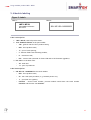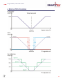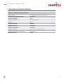
1
USER MANUAL
Longo modbus product
LMP-1.MP1H
Modbus RTU Temperature
Humidity Control panel
Version 2
SMARTEH d.o.o. / Poljubinj 114 / 5220 Tolmin / Slovenia / Tel.: +386(0) 388 44 00 / e-mail: [email protected] / www.smarteh.si
Longo modbus product LMP-1.MP1H
Written by SMARTEH d.o.o.
Copyright © 2015, SMARTEH d.o.o.
User Manual
Document Version: 001
November, 2015
i
Longo modbus product LMP-1.MP1H
STANDARDS AND PROVISIONS: Standards, recommendations, regulations
and provisions of the country in which the devices will operate, must
be considered while planning and setting up electrical devices. Work
on 230 V AC network is allowed for authorized personnel only.
DANGER WARNINGS: Devices or modules must be protected from
moisture, dirt and damage during transport, storing and operation.
WARRANTY CONDITIONS: For all LONGO LMP – if no modifications are
performed upon and are correctly connected by authorized personnel –
in consideration of maximum allowed connecting power, we offer
warranty for 24 months from date of sale to end buyer. In case of
claims within warranty time, which are based on material
malfunctions the producer offers free replacement. The method of
return of malfunctioned module, together with description, can be
arranged with our authorized representative. Warranty does not
include damage due to transport or because of unconsidered
corresponding regulations of the country, where the module is
installed.
This device must be connected properly by the provided connection
scheme in this manual. Wrong installation may result in device
damage, fire or personal injury.
Hazardous voltage in the device can cause electric shock and may
result in personal injury or death.
NEVER SERVICE THIS PRODUCT YOURSELF!
This device must not be installed in the systems critical for life (e.g.
medical devices, aircrafts, etc.).
If the device is used in a manner not specified by the manufacturer,
the degree of protection provided by the equipment may be impaired.
Waste electrical and electronic equipment (WEEE) must be collected
separately!
LONGO LMP-2 complies to the following standards:
EMC:
IEC/EN 61000-6-2(EN 50082),
IEC/EN 61000-6-4(EN 50081),
LVD:
IEC 61131-2,
Vibrations and climatic-mechanical: EN 60068-2-6,
EN 60068-2-27,
EN 60068-2-29.
Smarteh d.o.o. operates a policy of continuous development.
Therefore we reserve the right to make changes and improvements to
any of the products described in this manual without any prior notice.
MANUFACTURER:
SMARTEH d.o.o.
Poljubinj 114
5220 Tolmin
Slovenia
ii
Longo modbus product LMP-1.MP1H
Longo modbus product LMP-1.MP1H
1 ABBREVIATIONS................................................................................1
2 DESCRIPTION...................................................................................2
3 FEATURES.......................................................................................3
4 OPERATION.....................................................................................4
4.1
4.2
4.3
4.4
4.5
Operational modes................................................................................. 4
Functions ............................................................................................ 5
Parameters........................................................................................... 6
Modbus RTU variables memory...................................................................8
Modbus RTU settings memory...................................................................10
5 INSTALLATION.................................................................................11
5.1
5.2
5.3
5.4
Connection scheme............................................................................... 11
Mounting frame selection........................................................................ 13
Mounting instructions............................................................................. 14
Module labeling.................................................................................... 15
6 REGULATION DIAGRAM......................................................................16
7 TECHNICAL SPECIFICATIONS................................................................17
8 CHANGES .....................................................................................18
9 NOTES..........................................................................................19
iii
Longo modbus product LMP-1.MP1H
1 ABBREVIATIONS
Sorted by order of appearance in document:
SP
Set point
CP
Control Panel
TB
Touch Button
LCD
Liquid crystal display
1
Longo modbus product LMP-1.MP1H
2 DESCRIPTION
LMP-1.MP1H Modbus RTU Slave compatible control panel (CP) is used for room temperature and
humidity regulation using fan-coil or other heating/cooling devices.
Panel is equipped with temperature and light intensity sensor and four touch buttons (TB).
To increase, decrease temperature set point warmer, cooler TB should be pressed respectively.
Temperature SP is represented with right LCD bar-graph. While CP is in heating mode (temperature
SP is higher than actual room temperature), LCD SP bar is red and while in cooling mode
(temperature SP is lower than actual room temperature), LCD SP bar is blue. If actual temperature
is in SP +/- Dead band range, LCD SP bar is white.
With fan TB speed I, speed II, speed III, AUTO or OFF modes of operation can be selected.
Fan mode is represented with left blue LCD bar-graph.
With ECO (economy), OFF and ERR (error) signs on LCD, CP status is represented.
Color back ground LCD picture is possible to customize by using Smarteh LCD Composer software.
Light intensity sensor controls LCD intensity.
It is possible to display actual temperature value (0.5 °C resolution), temperature set point and
humidity (1 % resolution). The real time clock (HH:MM) can also be displayed. Enabling can be done
by MCU enable commands.
All parameters are accessible on panel's communication port. When panel is connected to Modbus
RTU Master equipment, parameters can be viewed and modified.
LMP-1.MP1H parameters and functions allows adaptation to desired system and regulation diagram.
Panel is able to regulate 2 or 4-pipe systems, depending on 4/2 pipe parameter.
2
Longo modbus product LMP-1.MP1H
3 FEATURES
Figure 1: LMP-1.MP1H module.
Table 1: Technical data
Room temperature and humidity measurement
2 touch buttons for temperature set point
2 touch buttons for manual fan speed, auto and controller off
10 position LCD bar-graph for temperature set point
4 position LCD bar-graph for manual fan speed, auto and controller off
Light intensity measurement
LCD intensity control
Step-less or 3 step fan motor controlling
Economic function
2/4 pipe heating cooling system supported
Balcony door/window function
Frost protection function
Color LCD display with background picture customization possibility1
1
For LCD background picture replacement, please refer to LCD Composer → Help.
3
Longo modbus product LMP-1.MP1H
4 OPERATION
Basic settings can be entered with panel Touch Buttons (TB).
Modes of operation and parameters can be set from any Modbus RTU Master equipment.
It is advised to press touch-buttons respectively with finger not faster than 1 press per second.
Press should be done with whole finger tip. Brief pressing could not activate the action, because of
protection against the noise and other influence.
4.1 Operational modes
LCD Display “stand-by mode”
The display is normally in this mode, if no TB is pressed in last ~5 seconds.
LED intensity is in correlation with Light intensity measurement (more light - brighter, less light darker).
Actual room temperature (0.5 °C resolution) and humidity (1 % resolution) is shown on the screen if
enabled.
LCD Display “SET mode”
First press on any TB will activate the display to “set mode” and LCD intensity will be put to
maximum. No action regarding the pressed TB is done. Further pressings on any TB will make the
change(bar-graphs) regarding the pressed TB.
Actual temperature set-point (regarding the right bar-graph) is shown on the screen if enabled.
Display will return to “stand-by mode” if touch buttons are not pressed for a while (~5 seconds).
Changing operation modes
Request for switching between CP normal and economic operating mode is done with lower left and
right TB pressed simultaneously : switch to economic mode
Request for switching between CP on and off operating mode is done with upper left and right TB
pressed simultaneously : CP switched off
Confirmation of above requested modes is done by Modbus RTU Master equipment by changing the
appropriate command bit (normal/economic, system on/off).
Normal
This is default mode for MP1H module. The control algorithm is executing regarding the parameters.
Economy
If set, controller will start cooling when room temperature will raise above max. temperature setpoint (SP) and stop when temperature will drop 1 °C below max. temp. SP. On the other hand, when
room temperature fall's below min. temp. SP controller will start heating and stop when
temperature will raise 1 °C above min. temp. SP.
In economic mode “ECO” sign appear on LCD.
Off
In this mode panel sends command to switch off all devices: hot valve, cold valve, fan. Temperature
LCD bar becomes white and “OFF” sign appear on LCD.
CP can be turned off using fan TB or System On/Off command. In this case cool, heat and fan
commands are switched off. Cool and heat commands are also switched off when temperature
measured by the panel is inside temperature dead band values (default dead band is 0.5 °C).
4
Longo modbus product LMP-1.MP1H
Error
In case of CP internal or communication fault, “ERR” sign appear on LCD.
Set
When any of four buttons is pressed more than certain time, “SET” sign appear on LCD and buttons
functioning is enabled. After “SET” sign is off, push buttons functions are disabled.
4.2 Functions
PI controller
Output variable range is 0 to 10000 (0 .. 100 %) in heating and/or cooling mode respectively .
Values are used for analog/digital (0 .. 100 % / I.,II.,III. speed ) output reference for the fan speed
and/or the output for the heat/cool actuator (0 .. 100 % / On-Off valve).
The dynamics of PI calculation is defined by P& I parameters.
Example:
If proportional – P parameter (default = 25) is set to 1 and difference between measured
temperature and temperature set point is changed to +1 °C, the PI output value will change from
example 5000 to 5100. On the other hand if the difference is changed to -1 °C, PI output value will
change from example 5000 to 4900.
If integral – I parameter (default = 5) is set to 1 and difference between measured temperature and
temperature set point is +1 °C, the PI output value will increase every second by 1. On the other
hand if the difference is -1 °C, the PI output value will decrease every second by 1.
2/4 pipe system selection
While 4-pipe (factory default) system active, controller will activate hot water actuator when
heating is required and cool water actuator when cooling is required.
In case 2-pipe system is active, hot water actuator will be operated regardless whether heating or
cooling is needed. Mode of operation (closing, opening) is dependent on Winter/Summer parameter.
Example:
System selected is 2-pipe , summer mode active and SP is lower than room temperature. CP will
start cooling with activating heat valve. In 2-pipe system cool valve is always inactive.
Frost protection
Function activates heat command when room temperature measured by the panel drops below 7 °C.
This function has priority over all control panel integrated functions.
Window open
Panel will operate in special mode if opened window and opened balcony door are detected. This
function is enabled by enabling parameters Balcony door En. or Window En. When this function is
active and one of parameters Window or Balcony Door commands is active, fan will stop and valves
for heating and cooling will close (delay of 1 minute is add with Balcony door command).
5
Longo modbus product LMP-1.MP1H
4.3 Parameters
If parameter is set to logical “1”, is considered to be active, enabled or set. If parameter has
logical value “0” is considered to be inactive, disabled, or cleared.
Parameter can be status or command or both. When parameter is marked as status this means that
module is sending information to controller. On the other hand command represents request from
module to Modbus RTU Master equipment.
Communication: Normal state is “1”. If off, there is communication error or no communication
established.
Normal/Economic: When set Economic mode is enabled. Default value is “0” therefore normal mode
is selected.
Local/Remote: When “0”, Local mode is selected. In this mode CP uses set point set by TB.
In remote mode, “1”, CP uses set point received from other devices (HMI, Touch Panel,
OT1, ...) through communication channel.
Heat valve: When valve is opened “1” is reported, while “0” stands for closed valve
Cool valve: When valve is opened “1” is reported, while “0” stands for closed valve
System On/Off: If parameter is set to “0” CP functions are executing in normal mode. If set to “1”
Fan speed and all valves are OFF (closed).
Winter/Summer: Used only for two-pipe system to change calculation for Hot valve and Fan speed;
Winter – heating (“0”) to Summer – cooling (“1”)
4/2 pipe: Four-pipe system manages hot and cold water pipes simultaneously. Two-pipe system
manages only one pair of pipes (one valve, pump). Operation in two-pipe system is therefore
dependent on Winter/Summer (Change-over) parameter.
“0” = Four pipe system
“1” = Two pipe system
Fan speed I.: When this parameter is “1”, actual fan speed is I.
Fan speed II.: When this parameter is “1”, actual fan speed is II.
Fan speed III.: When this parameter is “1”, actual fan speed is III.
Fan speed mode : This parameter determines fan speed adjustment mode:
“0”: Manual
“1”: Auto
Balcony door En.: When switch for detecting opened balcony door is connected to the system, this
function should be enabled (“1”).
Balcony door switch: Parameter reports whether door are closed or opened
“1”: closed
“0”: opened
Window En.: When switch for detecting opened window is connected to the system, this function
should be enabled (“1”).
Window switch: Parameter reports whether window is closed or opened
“1”: closed
“0”: opened
Max. temp.: denotes max. SP temp. which is scaled to top of LCD temperature bar
Min. temp.: denotes min. SP temp. which is scaled to bottom of LCD temperature bar
P regulation par.: Proportional parameter for PI calculation algorithm on CP
6
Longo modbus product LMP-1.MP1H
I regulation par.: Integral parameter for PI calculation algorithm on CP
PI Dead band: Value of change for PI loop output.
Fan reference: denotes fan speed value requested by panel
Temp. SP: This value is taken into PI calculation algorithm
Room temp.: Room temperature measured by CP panel.
Auxiliary room temp.: Room temperature value from other sensor is taken into PI calculation as
room temperature instead of temp. value measured by CP panel.
Absolute PI out: Result of PI calculation algorithm used for fan speed and valve opening
Light intensity: Actual light intensity measured by sensor on CP
Min. light intensity: When Light intensity is lower than this parameter, LCD bar graph on CP turns off
Remote temp. SP: When Local/Remote parameter is active this parameter is taken into PI
calculation algorithm as SP.
Fan mode set: Fan mode on CP panel can be remotely changed by Modbus RTU Master equipment.
[0,1,2,3,4=Off,I.,II.,III.,auto]. The change is made by setting the Fan Remote Cmd. command
bit.
Remote Fan mode inc: When this command changes to active, Fan mode on CP panel will be changed
in increment-rotate way [->Off,I.,II.,III.,auto,->].
SP up: When this command changes to active, CP will increment SP for 1/10 of scale. It acts like
pressing on Warmer TB on CP.
SP down: When this command changes to active, CP will decrement SP for 1/10 of SP range. It acts
like pressing on Cooler TB on CP.
Real Time clock: Real time clock (HH:MM) value by Modbus RTU Master equipment for display on CP
panel. Displaying is enabled with RTC Enable command bit.
Fan DB Off: If this command is active, the Fan speed inside dead-band goes to Off. Otherwise it
remains in low speed.
Temp. display Enable: If this command is active, displaying of actual Room temperature on the CP
panel is enabled.
TB pressed: This parameter indicates that any of TB is pressed.
7
Longo modbus product LMP-1.MP1H
4.4 Modbus RTU variables memory
Table 2: Coils
Memory
Variable description
Range
Values
00001
Fan in Dband Off Command
0/1
Fan On/Fan Off
00002
Normal/Economy command
0/1
Normal/Economy
00003
Local/Remote command
0/1
Local/Remote
00004
Setpoint DOWN command
0/1
0/DOWN
00005
Setpoint UP command
0/1
0/UP
00006
System ON/OFF command
0/1
ON/OFF
00007
Winter / Summer command
0/1
Winter/Summer
00008
4/2 pipe System command
0/1
4 pipe/2 pipe
00009
Temp. Display Num Enable
0/1
Disable/Enable
00010
RTC Display Num Enable
0/1
Disable/Enable
00011
Fan Mode Increment Command
0/1
0/Led Up
00012
Fan Local/Remote Command
0/1
Local/Remote
00013
Balcony door status
0/1
Open/Closed
00014
Setpoint Display Only Enable
0/1
Disable/Enable
00015
Enable Balcony Door cmd.
0/1
Disable/Enable
00016
Unit °C / °F
0/1
°C / °F
Variable description
Range
Values
40001
Max. Temp. Set par. [0.01°]
0 .. 10000
0.00 to 100.00 °C
40002
Min. Temp. Set par. [0.01°]
0 .. 10000
0.00 to 100.00 °C
40003
P regulation parameter
0 .. 100
0 .. 100
40004
I regulation parameter
0 .. 100
0 .. 100
40005
PI Deadband par. [0.01°]
0 .. 10000
0.00 to 100.00 °C
40006
Min.Light Intensity par. [%]
0 .. 100
0 .. 100 %
40007
Remote Temp. Setp. [0.01°]
0 .. 10000
0.00 to 100.00 °C
40008
Fan Mode Set [Off,I.,II.,III.,Auto]
0 .. 4
Off,I.,II.,III.,Auto
40009
Real Time Clock Set Value
0 .. 23:0 .. 59
0 .. 23:0 .. 59
40010
Remote Temperature [0.01°]
0 .. 10000
0.00 to 100.00 °C
Table 3: Holding Registers
Memory
8
Longo modbus product LMP-1.MP1H
Table 4: Digital Inputs
Memory
Variable description
Range
Values
10001
Communication status
0/1
Error/OK
10002
Normal/Economy status
0/1
Normal/Economy
10003
Local/Remote status
0/1
Local/Remote
10004
Heat Valve status
0/1
Closed/Open
10005
Cool Valve status
0/1
Closed/Open
10006
System ON/OFF status
0/1
ON/OFF
10007
Winter / Summer status
0/1
Winter/Summer
10008
4/2 pipe System status
0/1
4 pipe/2 pipe
10009
Fan Speed I status
0/1
0/Speed I
10010
Fan Speed II status
0/1
0/Speed II
10011
Fan Speed III status
0/1
0/Speed III
10012
Fan Local/Remote Status
0/1
Local/Remote
10013
Fan mode Manual/Auto
0/1
Manual/Auto
10014
PushButton Pressed Status
0/1
Off/On
10015
Enable Balcony Door sts.
0/1
Disable/Enable
10016
Enable Window status
0/1
Disable/Enable
Variable description
Range
Values
30001
Max. Temp. Set val. [0.01°]
0 .. 10000
0.00 to 100.00 °C
30002
Min. Temp. Set val. [0.01°]
0 .. 10000
0.00 to 100.00 °C
30003
P regulation par.status
0 .. 100
0 .. 100
30004
I regulation par.status
0 .. 100
0 .. 100
30005
PI Deadband par. [0.01°]
0 .. 10000
0.00 to 100.00 °C
30006
Fan reference
0 .. 10000
0 .. 100.00 %
30007
Temp. Setpoint [0.01°]
0 .. 10000
0.00 to 100.00 °C
30008
Act. Room Temp. [0.01°]
0 .. 10000
0.00 to 100.00 °C
30009
Relative Humidity
0 .. 100
0 .. 100 %
30010
Act. Light intensity [%]
0 .. 100
0 .. 100 %
Table 5: Input Registers
Memory
9
Longo modbus product LMP-1.MP1H
4.5 Modbus RTU settings memory
Table 6: Holding Registers
Memory
Variable description
Range
Values
40090
EEprom Write Command 2
0/12345
0 -> 12345 = EEprom Write
40091
Not used
40092
Not used
40093
Not used
40094
Not used
40095
Temperature Offset
-1000 .. +1000
-10.00 to 10.00 °C
40096
Touch button Off sensitivity limit
1 .. 20
High sens. .. Low sens.
40097
Touch button On sensitivity limit
1 .. 20
High sens. .. Low sens.
40098
Modbus RTU slave address
1 .. 255
Default address is 1
0 .. 11
0 = 19200 bps (default)
1 =
600 bps
2 =
1200 bps
3 =
2400 bps
4 =
4800 bps
5 =
9600 bps
6 = 14400 bps
7 = 19200 bps
8 = 38400 bps
9 = 56000 bps
10 = 57600 bps
11 = 115200 bps
Other = 19200 bps
0 .. 3
0 = None
1 = None
2 = Odd
3 = Even (default)
Other = None
Modbus RTU Baud rate
40099
40100
NOTE: polling cycle faster than
500 ms can cause occasionally
timeout warnings.
Modbus RTU Parity
2 On change from 0 to 12345 the RTU settings memory (40091..40100) will be updated into the module Eeprom.
10
Longo modbus product LMP-1.MP1H
5 INSTALLATION
5.1 Connection scheme
Figure 2: Connection scheme
11
Longo modbus product LMP-1.MP1H
Table 7: K1
K1.1
N.C.
Not connected
K1.2
GND
Ground
K1.3
7 .. 30 V DC
Power supply input
K1.4
Standard RS-485 A
Data receive/send line A
K1.5
Standard RS-485 B
Data receive/send line B
K1.6
N.C.
Not connected
Table 8: LCD bars & Buttons
Active LCD bar presents actual set point relative to range
Min. temp. (bottom LCD bar) and Max. temp. (top LCD bar)
Bar 1 LCD
Temp. SP
Bar 2 LCD
Fan mode
I: minimum speed selected
II: middle speed selected
III: maximum speed selected
AUTO: auto speed selection
OFF: module functions switched-off
TB1
Fan mode
Increase Mode & speed selection
Fan mode
Decrease Mode & speed selection
Temp. SP Up
Increase by one step, step = (Max. temp - Min. temp) * 1/10
Temp. SP Down
Decrease by one step, step = (Max. temp - Min. temp) * 1/10
(Up-left)
TB2
(Down-left)
TB3
(Up-right)
TB4
(Down-right)
Table 9: S13
MODBUS RTU SETTINGS SOURCE
3
Switch 1
Switch 2
User settings, from Modbus RTU registers
OFF
OFF
Not used
OFF
ON
Not used
ON
OFF
Default factory settings active,
19200 bps/8 data bits/1 stop bit/EVEN
ON
ON
Reset LMP-1 module after switch S1 changed, to activate new settings.
12
Longo modbus product LMP-1.MP1H
5.2 Mounting frame selection
Smarteh has verified following lines to be compatible with LMP-1.MP1H module:
●
Bticino – Living, Light
●
Gewiss – Playbus, System
●
Vimar – Plana, Idea
●
Tem – Modul Soft, Modul Line
●
Master
Frames of other vendors most probably suits as well, but they were not verified by Smarteh. Before
installation verify compatibility of non listed frames.
Module housing has a fin on each side, which can be easily removed with knife cutter or pliers. This
adaptation enables housing to be build in various frame formats with two different depths. With
regard to frame used you may remove fin for housing to fit in.
Figure 3: MP1H module with removable fin.
13
Longo modbus product LMP-1.MP1H
5.3 Mounting instructions
Figure 4: Housing dimensions
Dimensions in milimeters.
All connections, module attachments and assembling must be done
while module is not connected to the main power supply.
Module should be positioned in the wall inside of the room. Avoid
direct sunlight or positioning near heating/cooling source object.
Recommended installation height is 1.5 m above floor level.
1. Set the correct LMP-1.MP1H settings (refer to Table 6 and Table 9).
2. Connect LMP-1.MP1H with appropriate cable to the connector K1, Modbus RTU Master
equipment and power supply source (refer to Table 7). Max. allowed tensile force is 30 N.
3. Put the LMP-1.MP1H in mounting frame
4. Cover LMP-1.MP1H with cover plate
Modbus RTU settings source is set with DIP switch on the back of the LMP-1.MP1H module (Table 9).
NOTE: Signal wires must be installed separately from power and high voltage wires in accordance
with general industry electrical installation standard.
14
Longo modbus product LMP-1.MP1H
5.4 Module labeling
Figure 5: Labels
Label 1:
Label 2:
LMP-1.MP1H
P/N:220MP151V01001
D/C: 40/11
S/N: MP1-S9-1100000003
Label 1 description:
1. LMP-1.MP1H is the full product name.
2. P/N: 220MP151V01001 is the part number.
•
220 – general code for LPC-2 product family,
•
MP1 – short product name,
•
15 – year of code opening,
•
V - denotes flush frame mounting module,
•
01 – derivation code,
•
001 – version code (reserved for future HW and/or SW firmware upgrades).
3. D/C: 40/11 is the date code.
•
40 – week and
•
11 – year of production.
Label 2 description:
1. S/N: MP1-S9-1100000003 is the serial number.
•
MP1 – short product name,
•
S9 – user code (test procedure, e.g. Smarteh person xxx),
•
11 – year (last two cyphers),
•
00000003 – current stack number; previous module would have the stack number
00000002 and the next one 00000004.
15
Longo modbus product LMP-1.MP1H
6 REGULATION DIAGRAM
16
Longo modbus product LMP-1.MP1H
7 TECHNICAL SPECIFICATIONS
Table 10: Technical specifications
Power supply
7 .. 30 V DC from an external source
Interconnection connector type
RJ-12 6/6
Power consumption
1W
Dimensions (W x H x D)
75 x 49 x 29 mm
Weight
50 g
Maximum altitude
2000 m
Mounting position
horizontal
Ambient temperature
0 to 50 °C
Ambient humidity
max. 95 %, no condensation
Transport and storage temperature
-20 to 60 °C
Protection class
IP 20
17
Longo modbus product LMP-1.MP1H
8 CHANGES
The following table describes all the changes to the document.
Date
V.
Description
18
Longo modbus product LMP-1.MP1H
9 NOTES
19
Longo modbus product LMP-1.MP1H
20