1
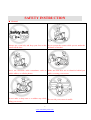
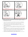
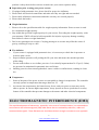
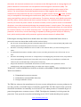
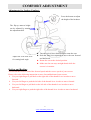
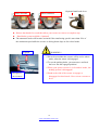
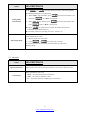
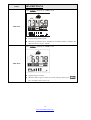
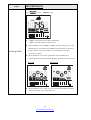
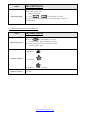
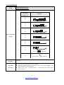
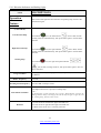
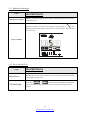
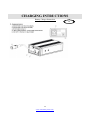
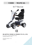
USERS MANUAL V8 964 Northpoint Blvd Waukegan, IL 60085 VITA MOBILITY WERKS 1 www.vitamobilitywerks.com CONTENTS 1. SAFETY INSTRUCTION……………………...……………………………………….……………………………..............3 2. ELECTOAGNETIC INTERFERENCE(EMI)………….……………………………………………………………….………6 3. TECHINCAL SPECIFICATIONS…………………………..…………….………………………………………………….…..8 4. COMFORT ADJUSTMENT…………….…………………………………………………………………..…………………...9 5. OPERATION OF CONTROL PANEL……………………………………………………………..………………………….11 6. CHARGING INSTRUCTION….……………….………………………………………....................................…..27 7. BATTERY INSTRUCTION & MAINTENANCE……………………………………………………………..………...…30 8. SCOOTER MAINTENANCE & REPAIR…..…………………………………………………………………...…..…..…32 9. TROUBLESHOOTING & FAULT REPAIR………………………………………………………….……...………………34 10. CIRCUIT DIAGRAM…….………..………………………………………………………………….....………………………35 11. VMW’S PATENT-‐SUSPENSION SYSTEM…….………………………………………………….……….…….35 12. BOM LIST DRAWING………………..........………………………………………..….…………………...………………36 13. WARRANTY DECLARATION……………………………………………………………………….…………………………37 14. CARE AND MAINTENANCE……………………………………………………….……………………………......………38 2 www.vitamobilitywerks.com SAFETY INSTRUCTION u General Always use a seat belt, and keep your feet on the Never operate the scooter while you are under the scooter all the time. influence of alcohol. Never use electronic radio transmitters such as Make sure that there are no obstacles behind you while reversing your scooter. walkie-talkies, or cellular phones. Do not make a sharp turn or a sudden stop while Do not ride your scooter in traffic. riding your scooter. 3 www.vitamobilitywerks.com Do not attempt to climb curbs greater than Do not leave your hands and legs off the scooter limitation show on Technical Specification when driving. Do not ride your scooter during snow in order to Do not allow unsupervised children to play near avoid accident on slippery road. this equipment while the batteries are charging. u Warning – Don’t operate your scooter for the first time without completely reading and understanding this user manual. 1. 2. 3. 4. 5. Don’t operate scooter on public streets and roadways. Be aware that it may be difficult for traffic to see you when you are seated on the scooter. Obey all local pedestrian traffic rules. Wait until your path is clear of traffic, and then proceed with extreme cautions. To prevent injury to yourself or others, always ensure that the power is switched off when getting on or off of the scooter. Always check that the drive wheels are engaged (drive mode) before driving. Do not switch off the power when the scooter is still moving forward. This will bring the chair to an extremely abrupt stop. Do not use this product or any available optional equipment without first completely reading and understanding these instructions. If you are unable to understand the warnings, cautions or instructions, contact a healthcare professional, the dealers or technical supports before attempting to use this equipment, otherwise, injury or damage may occur. There are certain situations, including some medical conditions, where the scooter user will 4 www.vitamobilitywerks.com 6. 7. 8. 9. 10. 11. 12. 13. 14. 15. 16. 17. 18. 19. 20. need to practice operating the scooter in the presence of a trained attendant. A trained attendant can be defined as a family member or care professional especially trained in assisting a scooter user in various daily living activities. Consult with your physician if you are taking any medication that may affect your ability to operate your scooter safely. Do not attempt to lift or move a power scooter by any of its removable parts including the armrests, seats or shrouds. Personal injury and damage to the power chair may result. Never try to use your scooter beyond its limitations as described in this manual. Please do not sit on your scooter while it is in a moving vehicle. Keep your hands away from the wheels (tires) while driving scooters. Be aware that loose fitting clothing can become caught in the drive tires. Consult your physician if you are taking prescribed medication or if you have any certain physical limitations. Some medications and limitations may impair your ability to operate scooters in a safe manner. Be aware when the drive mode is unlocked or locked. Don’t remove anti-tipper if there is any-tipper equipped with the scooter. Contact with tools can cause electrical shock and do not connect an extension cord to the AC/DC converter or the battery charger. Do not attempt to lift or move your scooter by any of its removal parts, such as the armrests, seats, or shroud. When climbing an incline, don’t drive at an angle up the face of the incline. Drive your scooter straight up the incline. This greatly reduces the possibility of a tip or a fall. Don’t climb a slope steeper than the scooter’s limitation. Don’t attempt to have your scooter proceed backward down any step, curb or other obstacle. This may cause the scooter to fall or tip. Always reduce your speed and maintain a stable center of gravity when cornering sharply. Don’t corner sharply when driving scooters at higher speeds. Operating in rain, snow, salt, mist conditions and on icy or slippery surfaces may have an adverse affect on the electrical system. Never sit on your scooter when it is being used in connection with any type of lift or elevation product. Your scooter is not designed with such use in mind and any damage or injury incurred from such use is not the responsibility of VMW. u Modifications Vita Mobility Werks has designed and engineered power scooters to provide maximum utility. However, under no circumstances should you modify, add, remove, or disable any part or function of your power scooter. Personal injury and damage to the power chair may result. 1. Do not modify your power scooter in any way not authorized by VMW. Do not use accessories if they have not been tested or approved for VMW products. 2. Get to know the feel of your power scooter and its capabilities. VMW recommends that you 5 www.vitamobilitywerks.com u 1. 2. 3. 4. perform a safety check before each use to make sure your scooter operates safely. Inspections prior to using your power scooter: If equipped with pneumatic tires, please check for proper tire inflations. Please check all electrical connections and make sure they are tight and not corroded. Please check all harness connections and make sure they are secured properly. Please check the brakes. u Weight limitation. 1. Please refer to the specifications table for weight capacity information. Power scooter is rated for a maximum weight capacity. 2. Stay within the specified weight capacity for your scooter. Exceeding the weight capacity voids your warranty. VMW will not be held responsible for injuries or property damage resulting from failure to observe weight limitations. 3. Don’t carry passengers on scooters. Carrying passengers on scooter may affect the center of gravity, resulting in a tip or a fall. u Tire inflation 1. If your scooter is equipped with pneumatic tires, it is necessary to check the air pressure at least one time a week. 2. Proper inflation pressures will prolong the life your tires and ensure the smooth operation while riding. 3. Do not under-inflate or over-inflate your tires. It is critically important that 30-25 psi (2-2.4bar) tire pressure be maintained in pneumatic tires at all times. 4. Inflating your tires from an unregulated air source could over-inflate them, resulting in a burs tire. u Temperature 1. Some of the parts of the power scooter are susceptible to change in temperature. The controller can only operate in temperature that ranges between -25 ~ 50 . 2. At extreme low temperatures, the batteries may freeze, and your power scooter may not be able to operate. In extreme high temperatures, it may operate at slower speeds due to a safety feature of the controller that prevents damage to the motors and other electrical components. ELECTROMAGNETIC INTERFERENCE (EMI) The rapid development of electronics, especially in the area of communications, has saturated our environment with electromagnetic (EM) radio waves that are emitted by television, radio and communication signals. These EM wave are invisible and their strength increases as one approach 6 www.vitamobilitywerks.com the source. All electrical conductors act as antennas to the EM signals and, to varying degrees, all power wheelchairs and scooters are susceptible to electromagnetic interference (EMI). The interference could result in abnormal, unintentional movement and/or erratic control of the vehicle. The United States Food and drug Administration (FDA) suggests that the following statement be incorporated to the user’s manual for all power scooter like the V8. Power scooters may as susceptible to electromagnetic interference (EMI), which is interfering electromagnetic energy emitted from sources such as radio stations, TV stations, amateur radio (HAN) transmitter, two-‐way radios, cellular phones and alarm systems of shops. The interference (from radio wave sources) can cause the power scooter to release its brakes, move by itself or move in unintended directions. It can also permanently damage the powered scooter’s control system. The intensity of the EM energy can be measured in volts per meter (V/m). Each powered scooter can resist EMI up to a certain intensity. This is called “immunity level”. The higher the immunity level the greater the protection. At this time, current technology is capable of providing at least 20 V/m of immunity level, which would provide useful protection against common sources of radiated EMI. Following the warnings listed below should reduce the chance of unintended brake release or powered scooter movement that could result in serious injury: 1. Do not turn on hand-‐held personal communication devices such as citizens band (CB) radios and cellular phones while the powered scooter is turned on. 2. Be aware of nearby transmitters such as radio or TV stations and try to avoid coming close to them. 3. If unintended movement or brake release occurs, turn the powered scooter off as soon as it is safe. 4. Be aware that adding accessories or components, or modifying the powered scooter, may make it more susceptible to interference from radio wave sources (Note: It is difficult to evaluate the effect on the overall immunity of the powered scooter). 5. Report all incidents of unintended movement or brake release to the powered scooter manufacturer, and note whether there is a radio wave source nearby. TURN OFF YOUR POWERED SCOOTER AS SOON AS POSSIBLE WHEN EXPERIENCING THE FOLLOWING: Ø Unintentional scooter movements Ø Unintended or uncontrollable direction. Ø Unexpected brake release The FDA has written to the manufacturers of power scooters asking them to test new products to be sure they provide a reasonable degree of immunity against EMI. The FDA requires that a powered wheelchair should have an immunity level at least 20 V/m, which provides a reasonable degree of protection against more common sources of EMI. The higher the immunity level the greater the protection. Your powered scooter has an immunity level of 20 V/m that should protect against 7 www.vitamobilitywerks.com common sources of EMI. Warning: The scooter itself can disturb the performance of the electromagnetic fields such as emitted by alarm systems of shops TECHNICAL SPECIFICATIONS MODEL V8 WEIGHT CAPACITY 400 lbs SEAT: TYPE/SIZE 20" A2 DRIVE WHEEL 13"x4" V8X 14” X 6.5” FRONT CASTER (WHEEL) 13"x4" REAR CASTER (ANTI-TIPPER) None MAX SPEED 8MPH 12V 50Ah x 2pcs or 12V 62Ah x BATTERY SPECIFICATIONS 2pcs(Optional) BATTERY RANGE 22 miles/28 miles CHARGER TYPE 5Amp,Off Board120/240 Volt,50/60Hz CONTROLLER TYPE S-Drive 120 Amp MOTOR TYPE 700W 4-POLE MOTOR WEIGHT: W/ BATTERY 238 lbs WEIGHT: W/O BATTERY 176 lbs TURNING RADIUS 45.6" SUSPENSION FULL LENGTH 62” WIDTH 28” HEIGHT 53” SEAT WIDTH 20” SEAT HEIGHT 18” SEAT DEPTH 19” BACK HEIGHT 30” WHEEL BASE 38” GROUND CLEARANCE 5” LEG ROOM 16” 8 www.vitamobilitywerks.com COMFORT ADJUSTMENT Adjustments for Seating Comfort: Press the bottom to adjust the height of the headrest. The flip-up armrest height can be adjusted by turning the adjustment dial. Adjust the seat back lever for seating back angle. l Turn the swivel lever downwards to rotate the seat. l Push the front lever upwards to move the seat forward and backward. l Rotate the seat to the desired position. l Make sure the seat stays straight ahead while the scooter is in motion. Driving and Braking You can use the lever to control the forward speed and the reserve speed of your scooter. Please refer to the following instruction to move forward/backward your scooter. Ø Use your right finger to pull back on the right side of the throttle lever in order to move forward. Ø Use your left finger to push the left side of the throttle lever in order to move forward. Ø Use your left finger to pull back on the left side of the throttle lever in order to move backward. Ø Use your right finger to push the right side of the throttle lever in order to move backward. 9 www.vitamobilitywerks.com Move forward *Optional hand brake lever Move backward l Release the throttle lever and then allow your scooter to come to a complete stop. l Hand brake system available. (Optional) l The automatic brake will become activated if the transferring speed is more than 30% of the maximum speed while the scooter is driving down-slope at free-wheel mode. Engaged Disengaged (Free Wheel) WARNING ! ² Please be noted that the scooter will be at free-wheel mode, when the motor is disengaged. ² To use the parking brake, you must move and lock the lever into the engaged position! ² When your power scooter is in freewheel mode, the braking system is disengaged! ² Stand to the side of the scooter to engage or disengage freewheel mode. Never sit on a scooter to do it! 10 www.vitamobilitywerks.com Tiller Positioning Ø Ø Ø Press down the lever and adjust it into your preferred position. Never attempt to adjust the tiller while the scooter is in motion. Make sure the tiller is at a comfortable setting and located securely. 11 www.vitamobilitywerks.com OPERATION AND CONTROL PANEL 1. Control Panel Layout LCD(Liquid Crystal Display)Power Scooter Control Panel, TN Type LCD Screen LED LED Indications Indications Right Indicator Left Indicator Headlight Position Light Parking Indicator Warning Indicator Left Indicator control SET button Position Light control High / Low speed control Right Indicator control Parking lamp control MODE button Headlight control Horn Button Function & Adjustment Buttons 12 www.vitamobilitywerks.com 2. Functions 2-1 Function Descriptions SPECIFICATION FUNCTION 1 Temperature “°C” / “°F” modes 2 Clock Hour / Minute display and setting 3 Odometer Trip Meter ODO (99999 max), TRIP (999.9 max) Sum of distance and time 4 Speedometer 7 Segment display (2 1/2 digits +1 decimal) “km/h” and “mph” symbol 5 High /Low Speed & Turn Status Indicated as icon and 6 Power Indicator Battery remaining capacity and charging indicator (6 squares + Battery icon) 7 Headlight Blue LED Including “Power-Saving” mode 8 Position Light Orange LED Placed inside headlight, used while rainy or gloomy weather 9 Brake Light Including “Brake-Mode” and “Parking Mode” 10 Left-Right Direction Indicators Green LED Flash mode Auto switch-off after 30 seconds Parking Light Red LED Including “Parking Mode” Right/Left indicators flash simultaneously 11 12 Malfunction Messages Red LED Malfunction code: 7 Segment display (1digit) + warning symbol 13 Power-On-Self-Test All LED illuminated 13 www.vitamobilitywerks.com 2-2 Buttons & Indicators ITEM DESCRIPTION Function & Adjustment Buttons: LED Indicators LCD Backlight Connecter Left-Indicator (Green) Right- Indicator (Green) Position Light (Amber) Headlight (Blue) Warning Indicator (Red) Parking Indicator (Red) Illumination: 700 mcd min (Orange color) CON1: 20PIN 3. Usage Conditions ITEM Voltage SPECIFICATION DC 24 V Operation Voltage DC 16 ~32 V Storage Temperature -40°C ~ 90°C Operation Temperature -25°C ~ 55°C Meter Angle at Handle Cover 30° of elevation while scooter assembly (LCD orientate to 6 o’clock) 14 www.vitamobilitywerks.com 4. Characteristics Test General Characteristic Performance Test (20 ± 5 ) Hardware Circuit: ITEM SPECIFICATION Lowest Operation Voltage 16V max RESULT (n = V Dynamic: 200 mA max (backlight and all of LED illuminated) Consuming Current (VB = 24.0V) MA mA Static: 5 mA max (Key Off status) 5. Operation of Control Panel 5-1. Temperature Meter ITEM Operation Feature Tolerance DESCRIPTIONS Temperature sensor (NTC) detects and transfers the signal to a temperature value. ± 2°C Press to switch to TEMP-Mode: Working Mode * Display Range : -20°C ~50°C / -4°F ~122°F 15 www.vitamobilitywerks.com ) ITEM Setting Mode (Unit Switch) DESCRIPTIONS l Press + for more than 2 seconds to enter Setting-Mode, and the backlight illuminates in the meantime. l When “°C” or “°F” flashing, press Exit Setting Mode to switch °C / °F. Under Setting-Mode, when 1) idle for more than 20 seconds, 2) press + for more than 2 seconds, the system will save the last setting value automatically and back to Working-Mode. 5-2. Clock ITEM Tolerance Initial Setting Value DESCRIPTIONS ±2 sec. (per day) 『Hour: Min』mode :『AM 12:00』 Press to switch to CLOCK-Mode: AM PM Working Mode l Display Range : AM12:00 ~ PM11:59 During 1 to 9 o’clock, “0” of tens on Hour digits won’t show on LCD. 16 www.vitamobilitywerks.com ITEM DESCRIPTIONS Press + for longer than 2 seconds to enter Setting-Mode, the backlight illuminates in the meantime. 1) When “Hour” digit is flashing, press Setting Mode (Time Switch) then press into “Min” setting mode. 2) When “Min” digit is flashing, press press l If press to increase the number, and to increase the number, then back to “Hour” setting mode. for longer than 2 seconds, the number will increase continually till the button released. l The setting value runs cyclically (only 2 sec. from 0 to 9) Under Setting-Mode, when 1) idle for longer than 20 seconds Exit Setting Mode 2) press + for longer than 2 seconds, the system will save the last setting value automatically and back to Working-Mode. 5-3. Odometer ITEM Operation Features Units Switch DESCRIPTIONS OptoCoupler sensor detects the signal and then converts into a distance value. When speedometer was set as 「km/h」, the odometer displays as kilometer. 「mph」, the odometer displays as mile. 「/h」, means the odometer is displaying as travel hours. 17 www.vitamobilitywerks.com ITEM DESCRIPTIONS Press switching to『ODO』mode mph km/h ODO Mode l Display Range:00000~99999 l When the total distance ran to 99999km or 62149mile (99999÷1.609mile), the digits will be reset to zero “00000”. Press switching to『TRIP』mode TRIP Mode l Display Range:0.0~999.9 l When the distance goes to 999.9, the counter will stop, please press for 3 seconds to reset to zero “0.0”. 18 www.vitamobilitywerks.com 5-4. Speedometer ITEM Operation Features DESCRIPTIONS OptoCoupler sensor detects the signal and then converts into a speed value. When drive shaft runs at 2100 rpm, speedometer will display “60km/h”. Tolerance +15~20% Digits range 0.0 ~ 30.0 Setting Mode (Units Switch) Display Rate:0.5 l Press + for longer than 2 seconds to enter Setting-Mode, backlight illuminates in the meantime. l When 『km/h』 / 『mph』/ 『/h』are flashing, press the unit. 19 www.vitamobilitywerks.com to switch ITEM DESCRIPTIONS Press to enter 『SPEED』mode mph km/h l 「km/h」means the speed is counted as kilometer. 「mph」means the speed is counted as mile. l When SPEED was set on “km/h” or “mph”, even the waiting screen is not SPEED mode; LCD will switch to SPEED mode when WIP (accelerator) is Working Mode acting, and back to previous waiting screen automatically once WIP (accelerator) stopped. l When SPEED was set on “/h”, speedometer will be disabled (fit to non-speedometer model) and replaced by WIP (accelerator) operation screen. Forward l Backward When SPEED was set on “/h”, LCD won’t switch automatically to SPEED mode from another screen while WIP acted. 20 www.vitamobilitywerks.com ITEM DESCRIPTIONS Under setting mode, when 1) Idle for 20 seconds Exit Setting Mode 2) Press + for longer than 2 seconds, The system will save the last setting value automatically and back to Working-Mode. 5-5. High/Low Speed & Turn Indicators ITEM DESCRIPTIONS l Operation Features l Press to switch High / Low speed. (*Control signals: TRN, with memory storage) Take exterior turn-switch as determinant signal (*Control signals: TRN) High Speed: Symbols of Status Low Speed: Turn Status: Flicker Frequency (Flashing) 1 second 21 www.vitamobilitywerks.com 5-6. Power Indication ITEM DESCRIPTIONS Remaining Scale Bar Capacity (%) 100 (6) 85 (5) 70 (4) Battery Remaining 55 Capacity (3) 40 (2) 30 (1) and icon 20 Flicker Frequency Operation Characters Warning LED is flashing is flashing 2 seconds l l l The scale status only decreases, won’t increase. When the remaining capacity was less than 30%, warning sound (“Bi-Bi” - two short sounds) act at 1second intervals. While (1) Key OFF (2) Charging-Mode (3) Sleep-Mode, the warning sound will be released. 22 www.vitamobilitywerks.com ITEM DESCRIPTIONS Remaining Capacity (%) Scale Bar 40 (2) 55 (3) 70 (4) Charge Indication 80 (5) 90 (6) 100 (7) Increase Frequency Operation Character Remarks 0.5 second l l l Scale status only decreases, won’t increase. Take the PIN3(CH3) of charger as the determinant signal, when CH3 is grounded (L), LCD will enter Charging-Mode, not limited by “KEY ON” or “KEY OFF”. Any pressing of button will illuminate LCD backlight, and switch off automatically if no more pressing after 5 seconds. Above scale bar status only for reference, the accurate diagnosis is still subject to the indicator of charger. 23 www.vitamobilitywerks.com 5-7. Headlight ITEM DESCRIPTIONS Take exterior headlight switch as determinant signal. Operation Feature Power Saving Mode Usage Condition Determinant Condition Remarks l l Press button to switch on/off LED . LCD backlights will be turned on/off when headlight switching on/off. l l When motor is resting, power modulate down to 30% (Headlight) When motor acts, power modulate up to 100% (Headlight) While (1) KEY OFF (2) Power-Saving Mode (3) Sleep-Mode, the function will be disabled. l Power-Saving ð Full-Power : React immediately l Full-Power ð Power-Saving : 5 sec delay (1) Loop Load: 24V/50W max (2) With “short circuit” and “overload” protection 5-8. Position Light ITEM DESCRIPTIONS Take exterior position-light switch as determinant signal. Operation Feature Usage Condition Remarks l l Press button to switch on/off LED . LCD backlights will be turned on/off when back-up lamp switching on/off. While (1) KEY OFF (2) Power-Saving Mode (3) Sleep-Mode, the function will be disabled. (1) Loop Load: 24V/50W max (2) With “short circuit” and “overload” protection 24 www.vitamobilitywerks.com 5-9. Brake and Reversing Light ITEM Operation Feature DESCRIPTIONS Take exterior WIP / RBK / Headlight / Back-up lamps switch as determinant signal. l Control Mode l l Usage Condition Determinant Condition Remarks Flicker Frequency Judge to be “Brake” or “Handbrake” state, when WIP (accelerator) signal changed from actuated to neural position, and will recover automatically after 3 seconds (Brake-Light Mode). Judge to be “Reverse” state, the brake light flashes (Reversing-light Mode) When the headlight and position light was turned on/off, and the brake light will be turn on/off simultaneously. While (1) controller closed (2) Charging-Mode, the function will be disabled. l l Parking status is adjusted by “motor direction” and “controller” Warning sound of parking was managed by controller (1) Loop Load: 24V/50W max (2) With “short circuit” and “overload” protection (electric type) 1 second 25 www.vitamobilitywerks.com 5-10. Direction Indicators and Parking Light ITEM Operation Feature DESCRIPTIONS Take exterior left-right direction indicators and parking lamp switch as the determinant signal. (Control Mode) Left-direction lamp Press button once, the left-indicator start to flash, and the warning sound act simultaneously, then press button again to switch off the indicator. Right-direction lamp Press button once, the right-indicator start to flash, and the warning sound act simultaneously, then press button again to switch off the indicator. Parking lamp Press button once, the right /left/ park indicators start to flash, warning sound act, then press button again to turn off above indicators. Usage Condition Flicker Frequency Warning Sound Frequency While (1) KEY OFF (2) Charging-Mode (3) Sleep-Mode, the function will be disabled. 1 second One short “Bi” sound per second Left-Right indicators have priority to Parking lamp. <Ex.> Determinant Condition Remarks If “Parking lamp” turned on already, now you start “Right indicator” function, the flashing indicator lamps will change from both side (left & right) to right side, and the “Parking lamp” function will be closed. (1) Load circuit for left-direction light: 24V/50W max (2) Load circuit for right-direction light: 24V/50W max (3) With “short circuit” and “overload” protection 26 www.vitamobilitywerks.com 5-11. Malfunction Messages ITEM Operation Feature DESCRIPTIONS Take the connector pin (KEY) of controller as determinant signal, then converts it into digital code. When the controller send out an error message, warning indicator start flashing with controller signal at same time, the “Error message code” will show on LCD screen. Usage Condition 5-12. Power-On-Self-Test ITEM DESCRIPTIONS Initial Status When scooter power on, the control panel will take a self-test first; the backlight and all LCD segments will be tuned on for 3 seconds, then switch automatically to the default working mode. LCD Backlight When press + buttons, the LCD backlight will illuminate and turn off automatically if the button doesn’t be operated for longer than 5 seconds. 27 www.vitamobilitywerks.com CHARGING INTRUCTIONS Battery Charger Instruction 28 www.vitamobilitywerks.com 5A 2. SPECIFICATION Item BATTERY CHARGER (SWITCHING MODE) Model 4F24050 Output Current(DC) 5A Charging Voltage(DC) 28.8V Floating Voltage(DC) 27.6V Input Current (AC) 4/2 A Input Voltage(AC) 115 Vac Or 230 Vac 50/60 Hz (Manual Select) Efficiency AC-DC Operating Temperature 32°F ~ 104°F Performance Charging Method Battery Application Output Detection 80% min Switching Mode Constant current two stage constant voltage 24V Lead Acid Rechargeable Battery (20Ahr ~ 60Ahr) 1. 2. 3. 4. Operating Temperature Short Circuit Protection Output Voltage/ Current Limit Reverse Power Protection Overheat Detection 32~ 104 Degree (Fahrenheit) Measure L 7.5”×W 4”×H 2” Weight 2.1 lbs Color Black 29 www.vitamobilitywerks.com 3.OPERATING INSTRUCTION ð Manual adjust the correct input voltage (115V/230V) ð Connect the plug of battery charger to the socket of battery. ð Plug in the power cord. Turn the power on. Normally, the LED (Power) light will turn on when electric current passes. ð Charging starts. During charging, LED (Charge) will indicate Orange Light, when it turns to Green Light, that means well-charged. 4. LED INDICATION ð LED (POWER)-GREEN LIGHT ON: POWER ON ð LED (CHARGE)-ORGANGE LIGHT ON: CHARGING ð GREEN LIGHT ON: FULLY CHARGED 5. TROUBLE SHOOTING (1) If LED (POWER) light is off ð Check the input voltage (115V/230V) is the same as you adjust. ð If light is still off, please check and repair the battery charger. (2) If LED (CHARGE) light is off ð Check to see the clips connections is correct. ð If the battery is fully charged, the LED (CHARGE) light will be off. ð If light is still off, the battery may be defective. (3) If ORANGE light cannot turn to GREEN ð The battery can’t be charged. Please check and recover it. (4) If ORANGE LIGHT turns to GREEN LIIGHT immediately. ð Check to see the battery is fully charged. If not, the battery may be defective. Check and recover it. 6. CAUTION (1) To prolong charger life, do not connect the short output for long time. (2) Through charger change automatically and can be used for deeply discharged battery, do not use for extremely discharged, short aged and defective battery. (3) Use the charger in a well-ventilated area. (4) Use for LEAD ACID batteries 12V (13-60 Amp-Hr.) * 2 only. (5) Do not use for voltage input except the specified. (Make sure your present voltage input (115V or 230 V) and adjust manually) (6) Before using the battery charger, read all instructions and cautionary markings. (7) Use the battery charger in a well-ventilated area (8) To avoid the risk of injury, charge only lead-acid or gel cell type rechargeable batteries. (9) Please turn off the power after charging 30 www.vitamobilitywerks.com (10) Plug the off-board charger power cord into the charger port during battery charging. Off-Board Charger Port The off-board charger port is mounted on the tiller. WARNING ! ² ² ² ² ² Always charge your batteries in well-ventilated areas. The charger is intended for indoor use only. Please protect it from the moisture. For maximum performance, it is recommended that you replace both batteries at the same time if the batteries are weak. If the scooter will not be used for a long period of time, arrange to have the batteries recharge at least once every month to avoid deterioration of the batteries. Can we use a different charger? Please understand that chargers are selected specifically for particular applications and matched to the type and size of specific batteries. In order to charge your scooters safely and efficiently, we recommend use of the charger supplied as original equipment with your VMW product only. Any charging method resulting in batteries being charged individually is prohibited. 31 www.vitamobilitywerks.com BATTERY INSTRUCTION & MAINTENANCE l Read through the charger operating instruction before using it. l If you use your scooter every day, please charge its batteries as soon as you finish using it for the day. Your scooter will be ready each morning. l Avoid deeply discharging your scooter’s batteries. l Charge the battery at least 24 hours a week if the power chair or scooter has not been used. (This is to make sure that the electrolyte is always at the top level) l If the battery cannot be charged (Orange light cannot turn to Green) or if the Orange light turns to Green immediately, please check it with the technicians. The battery may be defective. l The voltage difference between the two batteries on a power unit cannot be more than 0.5 V; the battery case should be inspected for cleanliness and evidence of damage. l If the charger indicates red light, please kindly check if the charger is defected or if the cable wiring connection is poor. l Please keep the battery Θand connectors clean otherwise the charging condition will be poor. To Change the batteries in your scooters: l l l l l l l Remove the battery cover and captain seat. Unfasten the battery tie-down strap. Disconnect the battery harnesses properly. Disconnect the battery cables from the battery terminals. Remove the old batteries from the battery wells. Place a new battery in each battery well. Connect the red battery cable to the positive (+) battery terminal and then connect the black battery cable to the negative (-) battery terminal. l Reposition the terminal boots over the battery terminals. l Reconnect the battery tie-down strap. l Reinstall the battery cover and seat back to the scooter. 32 www.vitamobilitywerks.com Battery harnesses Battery Cable Battery Terminal WARNING! ² If you hand is wet or sweaty, Do NOT replace the batteries. ² Please always use two batteries of the same type at the same amp-hour capacity. ² Always replace both batteries at the same time. Please do not mix old and new batteries together. Wheel Replacement WARNING! Wheels should be replaced by an authorized dealer or qualified technician in a workshop. l Please refer to the following illustration for quick and safe wheel replacements. l Remove the key from the power switch. l Elevate the side of the scooter of which you want to remove the tires. Please ask the authorized dealer or qualified technician for extra help while elevating the scooter. l Remove the related nut, washers and hub from the axle (Please see figure below) l Please pull the tire off the inside/outside rim properly. l Slide the new tire back into the inside/outside rim properly. l Put the tire back onto the axle and tighten the drive wheel nut and washers onto the axle. 33 www.vitamobilitywerks.com SCOOTER MAINTENANCE & REPAIR Your power scooter is designed for minimal maintenance. However, like any motorized vehicle it requires routine maintenance. To keep your power scooters or power wheelchairs for years of trouble-free operation, we recommend you follow the following maintenance checks as scheduled. Maintenance Job Daily Electrical System ² Battery meter – Inspect the battery meter to determine if batteries are needed to be re-charged ² Controller / Display panel – Make sure they are not frayed or have any exposed wiring ² Check all plug & wiring connections for firm condition ² Have the batteries been fully charged before the daily operation ² Are all holder and screws firmly fixed and safe? ² Are all electric lighting system (if applicable) in working order Tyres & Wheels ² Have pneumatic tyres checked for necessary air pressure ² Front & Rear wheels must be able to spin smoothly without any interference ² Rear & Front wheels must spin without wobbling ² Visually inspect the tire tread. If it is less than 1/32”, please have your tires replaced by your local dealer. Others ² Motor brushes. We recommend that your authorized dealer inspect the brushes every six-month if your power scooter or power wheelchair is not operating smoothly. If the inspection determines excessive motor bushes worn out, they must be replaced otherwise the motor damage will result. 34 www.vitamobilitywerks.com Weekly Monthly Semi-Annual WARNING! Failure to maintain the brushes could void the power scooter warranty. To inspect or replace the motor brushes: 1. Unscrew the motor brush caps. 2. Remove the brushes. 3. Inspect the brushes for wear. 4. Replace the brushes if necessary. New Motor Brush Worn Motor Brush Less than 9 mm Motor Brush caps Inspect the state of the battery terminals every six months. Make sure that they are not corroded and the connections are tight. Periodically apply a thin film of petroleum jelly on the surface of terminals to guard against corrosion. CHECKS & REMINDER: l Make sure to keep the controller clean while protecting it from rain or water. Never hose off your power scooter or place it in direct contact with water. l Keep wheels free from lint, hair, sand and carpet fibers. l All upholstery can be washed with warm water and mild soap. Occasionally check the seat and back for sagging, cuts and tears. Replace if necessary. Do not store your scooter in damp or humid conditions as this will lead to mildew and rapid deterioration of the upholstery parts. l All moving mechanism will benefit from simple lubrication and inspection. Lubricate using petroleum jelly or light oil. Do not use too much oil, otherwise small drips could stain and damage carpets and furnishings etc. Always perform a general inspection of the tightness of all nuts and bolts. 35 www.vitamobilitywerks.com TROUBLESHOOTING & FAULT REPAIR If you experience any technical problems, it is recommended that you check with your local dealer before attempting to troubleshoot on your own. The following symptoms could indicate a serious problem with your power scooter. Contact your local dealer if any of the following arises: 1. Motor noise 2. Frayed harnesses 3. Cracked or broken connectors 4. Uneven wear on any of tires 5. Jerky motion 6. Pulling to one side 7. Bent or broken wheel assemblies 8. Does not power up 9. Powers up, but does not move 36 www.vitamobilitywerks.com CIRCUIT DIAGRAM VMW’S MANUFACTURER PATENT A brand new double-A arms suspension system. 37 www.vitamobilitywerks.com V8 - BOM LIST DRAWING 38 www.vitamobilitywerks.com WARRANTY DECLARATION Quality/ Warranty Declaration Products are to be fit for purpose and of excellent quality and performance. For valid warranty claims VMW will, at their discretion, replace/ repair/ refund items mutually agreed to be defective. VMW’s Warranty as Following: Ø Frame: Two-year limited warranty Ø Controllers: One-and-a-half-year limited warranty Ø Electronic Components and Charger: One-year limited warranty Ø Warranty Exclusion. The following items are not covered by warranty. ² Motor brushes ² Wheel Tires ² Arm Pads ² Seat Cushion ² Fuses / Bulbs ² Tiller Cover ² Rear Shroud ² Front Shroud ² Batteries and Consumable parts Any damage or defect of any nature occurring from the misuse, abuse of the product, improper operation or improper storage is not to be covered. The warranty is to start from the date of arrival of our products. VITA MOBILITY WERKS 39 www.vitamobilitywerks.com CARE AND MAINTENANCE Scooters require a minimal amount of care and maintenance. The following areas require inspection and/or care and maintenance. TIRE PRESSURE ð If equipped with pneumatic tires, always maintain the psi/bar/kPa air pressure rating indicated on each tire. ð Your power scooter comes with standard pneumatic tyres. If your power scooter comes with optional air tires, make sure to maintain the pressure of the tires between 30-35 psi. ð It is important that the psi/bar/kPa air pressure rating indicated on each tire be maintained in pneumatic tires at all times. Do not overinflate your tires. Low pressure may result in loss of control, and overinflated tires may burst. Failure to maintain the psi/bar/kPa air pressure rating indicated on the tires at all times may result in tire and/or wheel failure. Regularly inspect your scooter’s tires for signs of wear. CLEANING AND DISINFECTION ð Use a damp cloth and mild, non-abrasive cleanser to clean the plastic and metal parts of your scooter. Avoid using products that may scratch the surface of your scooter. ð If necessary, clean your product with an approved disinfectant. Make sure the disinfectant is safe for use on your product before application. ð Follow all safety instructions for the proper use of the disinfectant and/or cleaning agent before applying it to your product. Failure to comply may result in skin irritation or premature deterioration of upholstery and/or scooter finishes. BATTERY TERMINAL CONNECTIONS ð Make certain that the terminal connections remain tight and un-corroded. ð The batteries must sit flat in the battery wells. ð The battery terminals should face towards the inside of the scooter. WIRING HARNESSES ð Regularly check all wiring connections. ð Regularly check all wiring insulation, including the charger power cord, for wear or damage. ð Have your authorized dealer repair or replace any damaged connector, connection, or insulation that you find before using your scooter again. 40 www.vitamobilitywerks.com AXLE BEARINGS AND THE MOTOR/TRANSAXLE ASSEMBLY These items are all pre-lubricated, sealed, and require no subsequent lubrication. WHEEL REPLACEMENT If your scooter is equipped with pneumatic tires and you have a flat tire, you can have the tube replaced. If your scooter is equipped with a solid tire insert either the solid insert or the entire wheel must be replaced depending on the model. Contact your authorized dealer regarding replacement wheels for your scooters. MOTOR BRUSHES The motor brushes are housed inside of the motor transaxle/assembly. Your authorized dealer should inspect them periodi-cally for wear. CONSOLE, CHARGER, AND REAR ELECTRONICS ð Keep these areas free of moisture. ð Allow these areas to dry thoroughly if they have been exposed to moisture before operating your scooter again. STORING YOUR SCOOTER If you plan on not using your scooter for an extended period of time, it is best to: ð Fully charge its batteries prior to storage. ð Disconnect the batteries from the scooter. ð Store your scooter in a warm, dry environment. ð Avoid storing your scooter where it will be exposed to temperature extremes. Batteries that are regularly and deeply discharged, infrequently charged, stored in extreme temperatures, or stored without a full charge may be permanently damaged, causing unreliable performance and limited service life. It is recommended that you charge the scooter batteries periodically throughout periods of prolonged storage to ensure proper performance. DISPOSAL OF YOUR SCOOTER Your scooter must be disposed of according to applicable local and national statutory regulations. Contact your local waste disposal agency or authorized dealer for information on proper disposal of packaging, metal frame components, plastic components, electronics, and batteries. 41 www.vitamobilitywerks.com