1
SENSOR-LESS WASHING MACHINE
FIRMWARE USER MANUAL
32-BIT MICROCONTROLLER
FM3 Family
USER MANUAL
Publication Number FM3_AN706-00096
Revision 1.0
Issue Date Feb 26, 2015
U S E R
2
M A N U A L
FM3_AN706-00096-1v0-E, Feb 26, 2015
U S E R
M A N U A L
Target products
This application note describes the following products:
Series
FM3 Series
Feb 26, 2015, FM3_AN706-00096-1v0-E
Product Number
MB9AF111K, MB9AF312K
3
U S E R
M A N U A L
Table of Contents
1.
2.
3.
4.
5.
6.
7.
8.
9.
Introduction ..................................................................................................................................... 6
1.1
Purpose 6
1.2
Definitions, Acronyms and Abbreviations ............................................................................ 6
1.3
Document Overview ............................................................................................................ 6
System Scope ................................................................................................................................ 7
2.1
System Structure ................................................................................................................. 7
2.2
System Hardware Environment ........................................................................................... 7
2.3
System Development Environment ..................................................................................... 8
System Firmware Design ............................................................................................................... 9
3.1
FW Feature ......................................................................................................................... 9
3.2
FW Structure ..................................................................................................................... 10
3.3
Files Description ................................................................................................................ 13
3.4
FW Control Flow................................................................................................................ 14
System Function ........................................................................................................................... 15
4.1
Macro Define ..................................................................................................................... 15
4.2
Global Structure and Variable Define ................................................................................ 15
4.2.1
Variable for Motor Running ............................................................................... 16
4.2.2
Variables for FOC ............................................................................................. 17
4.2.3
Variables for Speed and Position...................................................................... 18
4.2.4
Variables for PID Control .................................................................................. 19
4.2.5
Variables for Washing Machine Application ...................................................... 20
4.3
Function List ...................................................................................................................... 22
Event Function.............................................................................................................................. 23
5.1
Motor FOC Run Process Function .................................................................................... 23
5.2
System Timer Event .......................................................................................................... 24
Interrupt Function ......................................................................................................................... 25
6.1
Interrupt Function List........................................................................................................ 25
6.2
Interrupt Priority Set .......................................................................................................... 25
6.3
Interrupt Generate Timer Flow .......................................................................................... 26
6.3.1
MFT & A/D Interrupt Generate Flow ................................................................. 26
6.3.2
DTTI Generate Flow ......................................................................................... 26
Demo Show .................................................................................................................................. 27
7.1
Demo System Introduction ................................................................................................ 27
7.1.1
Hardware Connection ....................................................................................... 28
7.2
Motor Debug ..................................................................................................................... 29
7.2.1
FW Interface Configuration............................................................................... 29
7.2.2
HW Check ........................................................................................................ 35
7.2.3
Speed Acceleration and Deceleration .............................................................. 37
7.3
Troubleshooting ................................................................................................................ 37
7.3.1
Motor Start-up .................................................................................................. 37
7.3.2
Protection ......................................................................................................... 38
7.3.3
Drum Direction Reversed ................................................................................. 38
7.3.4
PI Parameter .................................................................................................... 38
Additional Information ................................................................................................................... 39
Reference Documents .................................................................................................................. 40
Figures
Figure 2-1: System Structure ..................................................................................................................... 7
Figure 3-1: Structure of FW ...................................................................................................................... 10
Figure 3-2: Sub-files in Each Layer ........................................................................................................... 11
4
FM3_AN706-00096-1v0-E, Feb 26, 2015
U S E R
M A N U A L
Figure 3-3: Sensor-less WM FW Architecture .......................................................................................... 12
Figure 3-4: Diagram of the Control Flow .................................................................................................. 14
Figure 4-1: Diagram of Live Watch ........................................................................................................... 15
Figure 6-1: Free Run Timer Interrupt ........................................................................................................ 26
Figure 6-2: DTTI Interrupt ......................................................................................................................... 26
Figure 7-1: System Connection ................................................................................................................ 27
Figure 7-2: Motor Line Connection ........................................................................................................... 28
Figure 7-3: JTAG Line Connection ........................................................................................................... 28
Figure 7-4: AC Plug .................................................................................................................................. 28
Figure 7-5: Open the Workspace ............................................................................................................. 29
Figure 7-6: Interface File Diagram ............................................................................................................ 29
Figure 7-7: Motor Parameter Set .............................................................................................................. 30
Figure 7-8: Washing machine Parameter Setting ..................................................................................... 30
Figure 7-9: Inverter Carrier Frequency Setting ......................................................................................... 31
Figure 7-10: ADC Port Setting .................................................................................................................. 31
Figure 7-11: GPIO Port Setting................................................................................................................. 31
Figure 7-12: Function Select .................................................................................................................... 31
Figure 7-13: MCU Clock Setting ............................................................................................................... 32
Figure 7-14: A/D Converter Setting .......................................................................................................... 32
Figure 7-15: Variables Setting for Motor Running..................................................................................... 32
Figure 7-16: PI Parameter Setting ............................................................................................................ 33
Figure 7-17: Field Weaken and Limitation Setting .................................................................................... 33
Figure 7-18: UART Setting ....................................................................................................................... 33
Figure 7-19: Speed Setting ...................................................................................................................... 34
Figure 7-20: OOB and Weight Parameter Setting .................................................................................... 34
Figure 7-21: Un-Stop Parameter Setting .................................................................................................. 34
Figure 7-22: Protection Parameter Setting ............................................................................................... 34
Figure 7-23: Motor Run by J-link .............................................................................................................. 36
Figure 7-24: Motor Start-up Diagram........................................................................................................ 37
Tables
Table 2-1: MCU Development Environment ............................................................................................... 8
Table 3-1: Feature List of Sensor-less WM Solution................................................................................... 9
Table 3-2: Directory Description of Project ............................................................................................... 10
Table 3-3: File Description of Project ........................................................................................................ 13
Table 4-1: System Function List ............................................................................................................... 22
Table 5-1: Event Function List in the ‘Motor_Process() ............................................................................ 23
Table 5-2: Event Function List in the ‘Timer_Event()’ ............................................................................... 24
Table 6-1: System Used Interrupt Function .............................................................................................. 25
Table 7-1: Global Structure for HW Check ............................................................................................... 35
Table 7-2: Drum Running Status by the Command Speed ....................................................................... 36
Table 7-3: Typical Running Status by the Command Speed .................................................................... 37
Feb 26, 2015, FM3_AN706-00096-1v0-E
5
U S E R
M A N U A L
1. Introduction
1.1
Purpose
This user manual describes SPANSION inverter sensor-less washing machine solution, and describes how
to use inverter washing machine FW library.
The chapter 2 and chapter 3 describe the hardware and software work environment, which the project
should work with IAR 6.4 or an upper version tool. Chapter 4 and chapter 5 introduce the firmware structure
and function calling in system. After you have an overall understanding on this system, then you can study
more through chapter 5~7 which introduce the timer event function and interrupt time flowchart. In the last
chapter, there is a demo show to help user handle a new case when run this system.
1.2
1.3
Definitions, Acronyms and Abbreviations
HW
Hardware, at this document it means Inverter platform hardware board
FW
Firmware
FOC
Field Oriented Control
FEE
Fast Back-EMF Estimator
WM
Washing Machine
HFI
High frequency injection
CW
Clockwise
CCW
Counter clockwise
Document Overview
The rest of document is organized as the following:
Section 2 explains System Scope.
Section 3 explains System Firmware Design.
Section 4 explains System Function.
Section 5 explains Event Function.
Section 6 explains Interrupt Function.
Section 7 explains Demo Show.
6
FM3_AN706-00096-1v0-E, Feb 26, 2015
U S E R
M A N U A L
2. System Scope
2.1
System Structure
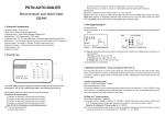
Figure 2-1 shows the whole overview of running system. IAR 6.4 is the main tool to debug and edit FW for
your project. GUI is also provided to make debug more easily. When build a new project, you must prepare
the IAR tool, J-Link and the motor driving board.
Figure 2-1: System Structure
IAR 6.4
USB
Data
J-Link Driver
WM Inverter Board
J-Link tool
Motor
GUI
USB
FTDI Driver
2.2
USB to RS232
USB
Port
RS232
Port
Data
System Hardware Environment
Below shows the brief information list of MCU used in wash machine inverter board.
CPU chip: Spansion MB9AF111K/ MB9AF312K.
CPU Frequency: 40MHz.
MCU pin number: 48pin.
RAM Space: 16Kbytes.
Code Space: 128Kbytes.
Demo HW version: WM-MAINBORAD-V0.3.1
Feb 26, 2015, FM3_AN706-00096-1v0-E
7
U S E R
2.3
M A N U A L
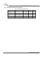
System Development Environment
Table 2-1: MCU Development Environment
Name
Description
IAR bedded
FW code edit , compile and
Workbench6.40
debug
J-Link
Manufacturer
Remark
N/A
N/A
N/A
Debug and Load FW by JTAG
N/A
N/A
Flash download program
N/A
N/A
Source Insight V3.50
Source code edit
N/A
N/A
Editor
Eclipse
Source code edit
N/A
N/A
Editor
SPANSION FLASH
LOADER
8
Part Number
N/A
N/A
FM3_AN706-00096-1v0-E, Feb 26, 2015
U S E R
M A N U A L
3. System Firmware Design
3.1
FW Feature
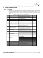
The features of the sensor-less inverter washing machine solution are shown in Table 3-1. All the functions
can be found in the demo project. But some core algorithms are made into library. User can set the
corresponding variables to enable or disable the function, which will be described in detail in the demo show
chapter.
No
Feature
Table 3-1: Feature List of Sensor-less WM Solution
Description
1.
Adjustable Carrier Frequency
2.
Rotor Position Estimator
3.
Motor Speed Calculate
4.
Field Weaken Control
Run motor in field weaken area to raise
speed
5.
6.
FOC Control
Self-adaption Start Up
Using FOC control algorithm
Adaptive to different load to start-up motor
7.
High Frequency Injection
The rotor initial position can be checked by
High Frequency Injection algorithm which
could shorten the start-up time
8.
Parameter Self Check
Motor’s stator resistor can be measured
during the startup process and d/q inductor
can be measured in the debug process.
9.
Speed regulate
10.
Brake
11.
12.
Current Sample
Remark
Carrier frequency can be set by the
corresponding variable in user interface
Rotor electrical phase angle was corrected
by the FEE estimator
Calculate speed by the FEE estimator
This function is used to accelerate motor
speed and decelerate motor speed by the
command from host via UART or debugger
Stop motor by brake down
Down motor’s speed by brake function
Dual shunts sample
Single shunt sample algorithm
DC voltage protect
A/D offset protect
Lock rotor protect
Protect
Power protect
IPM temperature protect
Motor phase lost protect
Over Current Protect
13.
OOB
Out of balance (OOB) load detect
14.
Weight
15.
Un-Stop Running
The weight of the load detect
Motor can switch running direction (CCW
and CW) without stopping motor
16.
UART
Feb 26, 2015, FM3_AN706-00096-1v0-E
Receive and transform data to Host PC
9
U S E R
3.2
M A N U A L
FW Structure
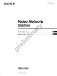
There are 5 layers in the FW structure of IAR, which is shown in Figure 3-1.
Figure 3-1: Structure of FW
The C source and Header files which are included in each layer are shown in Table 3-2
Table 3-2: Directory Description of Project
10
Layer
global
Folder
H01_global, S01_global
driver
H02_driver, S02_driver
module
H03_module, S03_module
app
H04_app, S04_app
user
H05_User, S05_User
Description
MCU system file
MCU register setting function such as GPIO,
interrupt, MFT, AD
Algorithm folder for basic motor control such as FOC
frame transform , SVM, math, PID, filter
Application folder for the files of application function
such as speed and position generator by FEE,
protection, motor start-up, filed weaken, brake,
weight, OOB, UART, etc.
Customer interface folder for the files for motor
configure and HW setting
FM3_AN706-00096-1v0-E, Feb 26, 2015
U S E R
M A N U A L
The sub-files in each folder are shown in Figure 3-2, and the structure of header files is the same as C files.
Figure 3-2: Sub-files in Each Layer
Feb 26, 2015, FM3_AN706-00096-1v0-E
11
U S E R
M A N U A L
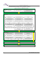
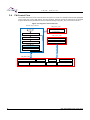
The relationship between each layer is shown as the diagram in Figure 3-3.
Figure 3-3: Sensor-less WM FW Architecture
User Layer
User interface
Main program entrance
Interrupt vectors
Motor Start-up
Single Shunt Sample
Brake
Un-Stop Running
Motor Speed Set
Rotor Angle Generate
Speed Calculation
Rotor Phase Angle Control
Voltage and Current Limit
OOB
Weight
UART
Voltage Protect
A/D Offset Protect
Over Current Protect
Lock Rotor Protect
Lose Phase Protect
IPM Temperature Protect
App Layer
Timer Event
Motor Interface
Clarke Transformer
Inverse Clarke Transformer
PI Regulator
Park Transformer
Inverse Park Transformer
SVPWM
Dead-time Compensation
Harmonic suppression
A/D Sample
Module Layer
LPF
Math
HFI
Parameter Self Check
Drive Layer
Global Layer
12
FM3_AN706-00096-1v0-E, Feb 26, 2015
U S E R
3.3
M A N U A L
Files Description
The detailed descriptions for each file are shown in Table 3-3.
Folder
S01_global
File
G04_Cm3.c
G04_Debug.c
Table 3-3: File Description of Project
Description
The file for MCU driver
Debug information for MCU driver
EquTrans.c
Filter.c
FOC axis convert
One order low pass filter
Math.c
The math module
SQRT,COS,SIN
PID.c
PWM.c
The PID module for current and speed PI
The SVPWM module
ADC_Sample.c
Angle_Generate.c
The ADC process module based on the ADC ISR
The rotor angle generate module
Brake.c
CV_Limit.c
The brake module including the speed down by brake
The FOC current and voltage limitation module
FieldWeaken.c
HW_Check.c
The Field Weaken module
HW Check module
Initial.c
ISR.c
MCU system initialization include interrupt priority list
The ISR file for all of the interrupt routine of the MCU
Motor_Run.c
The main file of the motor control including the main function
of FOC process of motor and the start/stop function of
motor
Motor_Startup.c
OOB.c
The motor start-up module
The OOB detect module
PID_Control.c
The PID control module that including the Speed PI, current
PI, PI parameter self-changing
Position_Calulate.c
Protect.c
The Position Calculate module
The Protect module
SingleShunt.c
Speed_Calculate.c
The Single Shunt module
The Speed Calculate module
SpeedSet.c
Timer_Event.c
The Speed set module
Timer event module
UART.c
UnStop.c
The UART module
The Unstop running module
The electrical weighing module
S02_Driver
Weight.c
Ignored
S05_User
CustomerInterface.c
Main.c
The motor parameter setting
Main function
Vector_Table.c
MCU interrupt vector list
S03_module
S04_app
Feb 26, 2015, FM3_AN706-00096-1v0-E
including
the
function
such
as
13
U S E R
3.4
M A N U A L
FW Control Flow
The control flow for the motor control is shown as Figure 3-4. There are 4 interrupts that are red highlighted
for the motor FOC control, hall capture, and AD converter. The timer events are executed in the end-less
loop and the timers are generated in the zero detection interrupt ‘ISR_MFT_FRT’ of the free run timer 0.
Figure 3-4: Diagram of the Control Flow
End-less loop in Main.c
ISR_ADC_unit1
Start
IPM temperature sample
and calculate
InitPowerOn
ISR_ADC_unit0
FeedWDT
Current U\V\W sample
Motor Start/Stop
DC bus sample and calculate
Timer_Event
Uart_Communicate
ISR_MFT_FRT
FOC control
Current restoration
14
PID
Speed &Position Generate
SVPWM
Weight & OOB
Other Algorithm
Protection (High Priority)
FM3_AN706-00096-1v0-E, Feb 26, 2015
U S E R
M A N U A L
4. System Function
This chapter will introduce the system function of the macro definition, global structure definition, and
function definition
4.1
Macro Define
The macro definition for the user will detailed describe in the last section ‘7.2.1FW Interface ’
4.2
Global Structure and Variable Define
Common used structure and variables that can be used for the motor running status debug will be detailed
listed in this section.
The variable for user interface can be found in section ‘7.2.1FW Interface
Any structure or variable that you want to watch can be pasted into the ‘Live Watch’ window of IAR as shown
in Figure 4-1.
Figure 4-1: Diagram of Live Watch
Feb 26, 2015, FM3_AN706-00096-1v0-E
15
U S E R
4.2.1
M A N U A L
Variable for Motor Running
Motor_stcRunParam
The structure is used to control motor run or stop and the basic running information for the motor such as
real running speed, DC bus voltage, washing machine work mode, etc. The detailed information can be
found in the comments for each variable.
typedef struct
{
int16_t i16WmCommandSpdRpm; //the command speed of drum from UART or
debugger online, unit:rpm
int16_t i16WmTargetSpdRpm;//the middle speed for the reference speed of
speed PI,unit:rpm
int16_t i16WmSpdRpmRt; //the real-time drum speed of washer
int16_t i16WmSpdRpmLPF; //the filtered drum speed of washer
int16_t i16MotorSpdRpmRt; //the real-time motor speed of washer
int16_t i16MotorSpdRpmLPF;//the filtered motor speed of washer
char_t cWorkMode;
//wash or spin work mode
char_t cRunStatus;
//run status: 0--stop,1--Run
char_t cRunDir;
//run direction: CW or CCW
uint16_t u16FaultCode;
//protection fault code
uint8_t u8InitStage;
//the start initial state machine
uint16_t u16Vbus;
//the DC bus voltage, unit:V
uint16_t u16VbusLpf;
//the DC bus voltage lpf value
uint32_t u32Q22_RotorEleTheta;//the rotor position angle
uint16_t u16BrakeTime; //brake time, unit:1ms
char_t cStartupcomplete; //flag for motor startup finish
char_t cCloseloop;
//flag for the motor closed loop running
} stc_MotorRunParam_t;
extern stc_MotorRunParam_t Motor_stcRunParam;
SpdSt_stc
The structure is used to the drum speed set. It is the global structure for the SpeedSet module that is
realized in file ‘S04_app/ SpeedSet.c’. Detailed information can be found in the comments for each variable,
the variables in this structure are not recommended to modify.
16
typedef struct stc_SpdSet
{
int16_t
i16SetSpeed;
//setting speed of drum, unit:rpm
int16_t
i16SetSpeedPre; //previous setting speed of drum, unit:rpm
uint16_t
u16SpdChgTime; //speed change time from spd A to B
uint16_t
u16CommandSpeed;
//the command speed of drum,unit:rpm
char_t
cWorkMode;
//the WM working mode: wash or spin
uint16_t
u16SpdChgCounter;
//the speed regulate counter
uint8_t
u8SpdChgStep;
//the speed change step for speed regulate
char_t
cMotorStartFlag;
//motor start flag
char_t
cMotorStopFlag; //motor stop flag
char_t
cRotateDir;
//motor running direction
uint16_t
u16AcceLmt;
//the acceleration limit at speed up
uint16_t
u16DeceLmt;
//the acceleration limit at speed down
uint16_t
u16SpeedMax;
//the maximum speed limit of drum speed
uint16_t
u16SpeedMin;
//the min speed limit of drum speed
} stc_SpdSet_t;
stc_SpdSet_t
SpdSt_stcSpdSet;
FM3_AN706-00096-1v0-E, Feb 26, 2015
U S E R
4.2.2
M A N U A L
Variables for FOC
The variables for the FOC control are introduced in this section.
D&Q axis Current and Voltage
Reference current value on the 2 axis rotation
frames
Reference current on D-axis ‘Idref’
Reference current on Q-axis ‘Iqref’
Cosine value of the rotor position used for the
frame transform
Sine value of the rotor position used for the
frame transform
current value on the 2 axis rotation frames
Real-time current on D-axis ‘Id’
Real-time current on Q-axis ‘Iq’
Cosine value of the rotor position used for the
frame transform
Sine value of the rotor position used for the
frame transform
Voltage value on the 2 axis rotation frames
Real-time voltage on D-axis ‘Vd’
Real-time voltage on Q-axis ‘Vq’
Cosine value of the rotor position used for
the frame transform
Sine value of the rotor position used for the
frame transform
Motor_Offset
The AD middle points of amplifier part on the HW are got in this structure. If the middle voltage of the
amplifying circuit for the phase current is changed, the AD offset result will be also changed at same
direction.
Motor_Offset
AD middle point for current Iu AD sample
AD middle point for current Iv AD sample
AD middle point for current Iw AD sample
2048 = 2.5 V, the offset error threshold is set by
‘AD_OFFEST_MAX_VALUE’
Startup_stcCtrl
The structure is used for the motor start-up control. The detailed information can be found in the comments
for each variable.
Flag for motor startup complete,1→start finished
Flag for motor closed loop running,1→speed closed loop
Flag for the motor startup stage
Flag for the motor startup and running level
Feb 26, 2015, FM3_AN706-00096-1v0-E
17
U S E R
M A N U A L
Limit_stcCalc
The structure is used for the FOC current and voltage limitation to ensure the reliability of the inverter. The
detailed information can be found in the comments for each variable.
D-axis voltage limit
Q-axis voltage limit
D-axis current limit, especially in field weaken
Q-axis current limit
Saturate phase current
FieldWeaken_stcCtrl
The structure is used for the filed weaken control. The detailed information can be found in the comments for
each variable.
Flag for the field weaken execution
Counter for the field weaken PI
The cycle of field weaken PI ,unit:1ms
The base drum speed of motor without filed weaken
Exit the field weaken by the load disturbance
The cycle of field weaken PI ,unit:1ms
The recorded base speed of drum speed
The recorded DC bus voltage when enter the field weaken
4.2.3
Variables for Speed and Position
Angle_stcGenerate
The structure is used for rotor position generate. The detailed information can be found in the comments for
each variable.
Rotor's output angle
Rotor's forward angle every PWM
Rotor's min forward angle every PWM
Rotor's forward angle calculated factor
Rotor pass hall number when start up
Spd_stcPar
The structure is used for rotor speed calculation output. The detailed information can be found in the
comments for each variable.
The output motor average speed
The output motor real time speed
The output WM average speed
The output WM real time speed
1/trans-ratio
Motor's real-time ele-speed
18
FM3_AN706-00096-1v0-E, Feb 26, 2015
U S E R
4.2.4
M A N U A L
Variables for PID Control
The structures used for PID control are introduced at this part.
Pid_stcCtrl
The structure is used for PID control that enables or disables the corresponding PI regulator. The detailed
information can be found in the comments for each variable.
Id PI Enable
Iq PI Enable
Speed PI Enable
field weaken PI Enable
Field weaken execution flag
Speed PI execution flag
Execute cycle of Id PI
Execute cycle of Iq PI
Execute cycle of speed PI, unit: ms
Execute cycle of field weaken PI, unit: ms
Pid_stcSpdPI
The structure is used for the speed PI regulator. The detailed information can be found in the comments for
each variable.
Kp parameter for speed PI, Q8 format
Ki parameter for speed PI, Q8 format
Kd parameter for speed PI, Q8 format
Pout of speed PI, Q16 format
Iout of speed PI, Q16 format
Dout of speed PI, Q16 format
Input error of speed PI, Q8 format
Previous input error of speed PI, Q8 format
Output of speed PI, Q8 format
Max output limit of speed PI, Q8 format
Min output limit of speed PI, Q8 format
Pid_stcIqPI
The structure is used for the q-axis current ‘Iq’ PI regulator. The detailed information can be found in the
comments for each variable.
Kp parameter for Iq PI, Q12 format
Ki parameter for Iq PI, Q12 format
Pout of Iq PI, Q20 format
Pout of Iq PI, Q20 format
Input error of Iq PI, Q8 format
output error of Iq PI, Q8 format
Max output limit of Iq PI, Q8 format
Min output limit of Iq PI, Q8 format
Feb 26, 2015, FM3_AN706-00096-1v0-E
19
U S E R
M A N U A L
Pid_stcIdPI
The structure is used for the d-axis current ‘Id’ PI regulator. The detailed information can be found in the
comments for each variable.
Kp parameter for Id PI, Q12 format
Ki parameter for Id PI, Q12 format
Pout of Id PI, Q20 format
Pout of Id PI, Q20 format
Input error of Id PI, Q8 format
Output of Id PI, Q8 format
Max output limit of Id PI, Q8 format
Min output limit of Id PI, Q8 format
FieldWeaken_stcPiParam
The structure is used for field weaken PI regulator. The detailed information can be found in the comments
for each variable.
Kp parameter for Field Weaken PI, Q8 format
Ki parameter for Field Weaken PI, Q8 format
Kd parameter for Field Weaken PI, Q8 format
Pout of Field Weaken PI, Q16 format
Iout of Field Weaken PI, Q16 format
Dout of Field Weaken PI, Q16 format
Input error of Field Weaken PI, Q8 format
Previous input error of Field Weaken PI, Q8 format
Output of Field Weaken PI, Q8 format
Max output limit of Field Weaken PI, Q8 format
Min output limit of Field Weaken PI, Q8 format
4.2.5
Variables for Washing Machine Application
The variables for the advanced application of the washing machine are introduced in this section.
Weight_stcCtrl
The structure is used for the weight control. The detailed information can be found in the comments for each
variable. The weight result and the inner data can be observed in this structure.
Weight start flag
Start detecting the power in weight
Flag for the speed acceleration finish
Weight finish flag, 1--finish 2--weight over time
Weight stage
Average power in one drum cycle at stable running N1
Sum power at weight speed up
Drum cycle at weight speed up
Original weight result of the load
Weight result of the load by the DC voltage compensation
Weight result of the load
Max weight time, unit: s
20
FM3_AN706-00096-1v0-E, Feb 26, 2015
U S E R
M A N U A L
OOB_stcCtrl
The structure is used for OOB detect. The detailed information can be found in the comments for each
variable.
OOB detect start flag
OOB detection stage, 4—OOB finished
Original OOB data of the load
OOB result to host
UnStop_stcParam
The structure is used for un-stop running. The detailed information can be found in the comments for each
variable.
Start unstop running
Stop unstop running
Run in force status flag
Angle compose start flag
Angle error between rotor and hall
Compose angle speed
Feb 26, 2015, FM3_AN706-00096-1v0-E
21
U S E R
4.3
M A N U A L
Function List
The functions for the system control are shown in Table 4-1.
Table 4-1: System Function List
Prototype
Description
Remark
void main(void)
Main function of the whole projection
Main.c
InitPowerOn()
The initial function for all the MCU resource
initial and key variable initial after the power
is on
Main.c
Motor_RunInit(Motor_CARRY_FREQ)
The function for the motor start control but
not for the motor start-up.
Motor_Run.c
Motor_StopControl()
The function for the motor stop control
Motor_Run.c
Uart_Communicate()
The main function
communication
static
Initial_Motor_RunPar(unsigned
sample_freq)
22
void
short
for
the
UART
UART.c
The key variable and the register initial at the
motor start
Motor_Run.c
void Motor_Process(void)
The main function of the motor control that is
called in each of the MFT zero detect ISR
Motor_Run.c
void Debug_Process(void)
The main function of the test mode for the
hall and HW check ,and is also called in each
of the MFT zero detect ISR
Motor_Run.c
void Debug_Watch(void)
The basic variable assignment for the motor
running
Motor_Run.c
void Timer_Counter(void)
The 1ms/5ms/50ms timer generated by the
MFT ISR
TimerEvent.c
void Timer_Event(void)
The timer event for the motor control or the
advanced function
TimerEvent.c
FM3_AN706-00096-1v0-E, Feb 26, 2015
U S E R
M A N U A L
5. Event Function
The functions for the motor control that are called in the MFT interrupt ‘Motor_Process()’ and timer
‘Timer_Event()’ are shown in Table 5-1 and Table 5-2 ,
5.1
Motor FOC Run Process Function
Table 5-1: Event Function List in the ‘Motor_Process()
Prototype
Description
UnStop_Run()
The main function for the un-stop running
Spd_EstimateCalculate()
The speed
estimator
Spd_Calculate()
The speed calculate function by the
estimator and hall module
The phase current restoration from ADC
converter
The function of the Clarke frame transform
Motor_Sense()
ClarkeTransform(&Motor_3sCurrent,
&Motor_2sCurrent)
Remark
calculate
function
by
the
ParkTransform(&Motor_2sCurrent,
&Motor_2rCurrent)
The function of the Park frame transform
Posi_Estimate(…)
The function of the rotor position estimator
Posi_Calculate()
The function of the rotor position calculation
from the estimator and hall module
Angle_Generate()
The function of the rotor position generation
Current_PI(…)
The d/q current PI regulator
Startup_SensorLessMotor ()
The motor start-up function for the
sensor-less motor
The function of the inverse Clarke frame
transform
InvertParkTransform(…)
InvertClackeTransform(…)
The function of the inverse Park frame
transform
SVPWM_Calc(…)
The SVPWM function
Write_MFT_OCCP(…)
The function for the OCCP register setting
according to the SVPWM calculate result
Weight_LoadMeasure()
The function for the weight
OOB_Detect()
The function for the OOB
Protect_OpenPhase(…)
The protection function for the open phase
detect
Feb 26, 2015, FM3_AN706-00096-1v0-E
23
U S E R
5.2
M A N U A L
System Timer Event
Table 5-2: Event Function List in the ‘Timer_Event()’
Prototype
Description
Remark
SpdSt_Function(…)
The speed set function used for the motor
speed acceleration or deceleration
1ms timer
SpdSt_PIReg(…)
The speed regulation function for the middle
speed generation
FieldWeaken_Control()
The main function for the field weaken
SpeedDownControl()
The function of the speed down by brake
PID_ParameterChange()
The function of the PID Parameter Change
Speed_PI(…)
The function of the speed PI regulator
Limit_Calculate()
The function of the FOC current and voltage
limitation
Protect_LockRotor()
The function of the motor lock protection
Protect_Voltage()
The function of the DC bus over and under
protection
Protect_IpmTemperature()
The function of the IPM temperature protection
Debug_Watch()
The basic variable assignment for the motor
running
The function of the UART lost protection
Uart_Protect()
24
5ms
50ms
FM3_AN706-00096-1v0-E, Feb 26, 2015
U S E R
M A N U A L
6. Interrupt Function
6.1
Interrupt Function List
Table 6-1: System Used Interrupt Function
6.2
Prototype
Description
Remark
__root void ISR_HardWatchdog(void)
The HW watch dog ISR
S04_app/ISR.c
__root void ISR_SoftWatchdog(void)
The software watch dog ISR
S04_app/ISR.c
__root void ISR_MFT_FRT(void)
The MFT zero detect ISR for the motor
control
S04_app/ISR.c
__root void ISR_MFT_WFG(void)
The HW over-current ISR
S04_app/ISR.c
__root void ISR_ADC_unit0(void)
The ADC unit0 ISR, trigger at the zero
point for the 3 shunts
S04_app/ISR.c
__root void ISR_ADC_unit1(void)
The ADC unit1 ISR for the IPM
temperature sample
S04_app/ISR.c
__root void Isr_UartRx(void)
UART receive interrupt by MFS3
S04_app/ISR.c
__root void Isr_UartTx(void)
UART transmit interrupt by MFS3
S04_app/ISR.c
__root void DefaultIRQHandler (void)
MCU exception interrupt
S04_app/ISR.c
Interrupt Priority Set
Each interrupt priority can be set by the function ‘void InitNVIC(void)’ which is located at the file
‘S04_app/Initial.c’. Users are not recommended to modify the file. The priority used for motor control is
shown as below.
void InitNVIC(void)
{
// INT priority
ConfPriorityForIRQ(16
ConfPriorityForIRQ(16
ConfPriorityForIRQ(16
ConfPriorityForIRQ(16
ConfPriorityForIRQ(16
ConfPriorityForIRQ(16
ConfPriorityForIRQ(16
ConfPriorityForIRQ(16
ConfPriorityForIRQ(16
}
Feb 26, 2015, FM3_AN706-00096-1v0-E
+
+
+
+
+
+
+
+
+
MFS3RX_IRQn, 4, PRI_LEVEL_6);
//UART receive
MFS3TX_IRQn, 4, PRI_LEVEL_6);
//UART Transmit
WFG_IRQn, 4, PRI_LEVEL_0);
//watchdog
EXINT0_7_IRQn, 4, PRI_LEVEL_0); //outside int
SWDT_IRQn, 4, PRI_LEVEL_1);//software watch dog
ADC0_IRQn, 4, PRI_LEVEL_2);
//adc0
ADC1_IRQn, 4, PRI_LEVEL_4);
//adc1
FRTIM_IRQn, 4, PRI_LEVEL_3);
//frt
OUTCOMP_IRQn, 4, PRI_LEVEL_6); //outcompare
25
U S E R
6.3
M A N U A L
Interrupt Generate Timer Flow
The diagram of the interrupt used for the motor control is briefly introduced in this section.
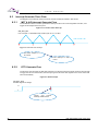
6.3.1
MFT & A/D Interrupt Generate Flow
The multifunction timer is used to generate the interrupt for the motor control algorithm execution, and
trigger the AD sample at the zero point.
Figure 6-1: Free Run Timer Interrupt
ISR_MFT_FRT
Free run timer 0, UP/DOWN mode, PWM cycle: 62.5 us, 16 KHz
Trigger AD unit0 and FOC interrupt
A/D unit0: sample U, V,
W current
FOC interrupt to drive
motor
6.3.2
DTTI Generate Flow
The DTTI0 is used to trigger the HW fault protection from the IPM. When the phase current is large enough
to trigger the HW over-current fault, the interrupt is got and all of the drive signals for the motor control will
shut off immediately.
Figure 6-2: DTTI Interrupt
ISR_MFT_WFG
IPM fault signal low voltage
H
L
Trigger
over
Current
Interrupt, PWM closed
26
FM3_AN706-00096-1v0-E, Feb 26, 2015
U S E R
M A N U A L
7. Demo Show
The primary steps are shown as following:
Hardware Connect
FW Interface
7.1
HW Check
Run Motor
Speed Acceleration and Deceleration
Demo System Introduction
The sensor-less wash machine solution can be adaptive to any type of washing machine which uses the
PMSM or BLDC motor. The connection diagram for debugger is shown in Figure 7-1.
Figure 7-1: System Connection
Feb 26, 2015, FM3_AN706-00096-1v0-E
27
U S E R
7.1.1
M A N U A L
Hardware Connection
It is necessary to connect the 3 lines shown as following:
1. Connect motor’s U, V, W phrase lines to inverter board, shown as below.
Figure 7-2: Motor Line Connection
U, V, W
Motor’s U, V, W lines can be connected to Inverter’s IPM’s output U, V, W port. And it is also recommended
to connect the U, V, W lines according to the definition of the motor.
2. Connect JTAG to Inverter, shown as below.
Figure 7-3: JTAG Line Connection
J-Link
Note:
If there is no isolator between the J-link and the HW, you must unplug the AC power and use the battery of
your note book.
3. Connect the AC line for the inverter board as shown in Figure 7-4 .
Figure 7-4: AC Plug
AC Power
28
FM3_AN706-00096-1v0-E, Feb 26, 2015
U S E R
7.2
M A N U A L
Motor Debug
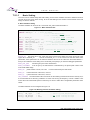
The debug method on the new motor is described in this section when you finish the hardware connection
with the motor. Click the IAR program to open the IAR, and open the ‘EWW’ file of the inverter washing
machine workspace at the location you’ve stored on your computer as shown in Figure 7-5.
Figure 7-5: Open the Workspace
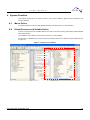
7.2.1
FW Interface Configuration
All of the variables reserved for the user interfaces are located in the file ‘S05_user/ CustomerInterface.c’
and the macro definitions are located in the file ‘H05_user/ CustomerInterface.h’. Both files are highlighted,
as shown in Figure 7-6.
Figure 7-6: Interface File Diagram
Feb 26, 2015, FM3_AN706-00096-1v0-E
29
U S E R
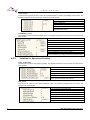
7.2.1.1
M A N U A L
Basic Setting
The motor can be started easily after basic setting. So the basic variables and macro definitions must be
correctly set for the motor demo running. All of the HW settings in this section must be based on the HW
design of HW user manual.
A. Basic Variables Setting
The basic variables can be set in the c source file ‘S05_user/ CustomerInterface.c’.
Figure 7-7: Motor Parameter Set
/** UI_0101 configure motor parameter */
#define MOTOR_ID
0 // motor ID number
// 0 --> new motor param,
// >=1 -->already debugged motor.
#if 0== MOTOR_ID
// new motor param -->LS BLDC
uint8_t Motor_pole_pairs = 12;
// the pole pairs of rotor
float
Wm_TransRate = 1;
// TransRate of washer,DD-->1, BLDC-->TBD
float
Motor_CurrentMax = 6.0;
//max peak phase current,unit,A
float
Motor_Rs
= 2.1; // phase resistor of motor,unit:ohm
float
Motor_Ld
= 17.5;
float
Motor_Lq
= 22.5;
float
Motor_EsMin
= 6.0; //the most min spd may be at 20r/min
#endif
MOTOR_ID:
The motor ID for user, if the new motor is used for the debug, the motor can be set in the
region ‘#if 0== MOTOR_ID
’ and set the MOTOR_ID = 0. If the motor runs well with these motor
parameters, these parameters can be fixed and added at the end of the ‘S05 user/ CustomerInterface.c’’.
And you can switch the motor debug more conveniently and quickly if you have the debugged parameters.
Motor_pole_pairs:
it must be got by the motor manufacturer
Motor_CurrentMax:
it can be got by the manufacturer or determined by the phase peak current at the
motor brake stable stage
Motor_Rs:
phase resistor of motor, unit: ohm.
It can be measured by the multi-meter.
Motor_Ld:
d-axis inductance of the motor, unit: mH.
Motor_Lq:
q-axis inductance of the motor, unit: mH.
Wm_TransRate: The transmission ratio of the motor for the washing machine must be also correctly set, It
is recommended to set the Wm_TransRate =10 if the max running ele-frequency of motor >1000Hz. That
means the motor mechanical speed is reduced by 10 times to make other configuration parameters more
robust.
The WM Parameter can be configured as Figure 7-8.
Figure 7-8: Washing machine Parameter Setting
/** UI_0102 configure WM parameter */
char_t WM_cType
= DD;
// wahser type:DD,DDM,BLDC,BLDCM
int32_t WM_MinSpd
= 30;
// min speed of drum,unit:rpm
int32_t WM_MaxSpd
= 2000;
// max speed of drum,unit:rpm
30
FM3_AN706-00096-1v0-E, Feb 26, 2015
U S E R
M A N U A L
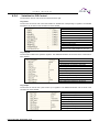
Inverter Parameter Configuration
The inverter carrier frequency can be set by the reserved variable, but the variables in this part are not
recommended to modify for the washing machine application.
Figure 7-9: Inverter Carrier Frequency Setting
/** UI_0103 configure inverter parameter*/
uint16_t Motor_CARRY_FREQ = 16000; //carrier frequency of motor driver,unit:Hz
uint32_t RelayDelayOnTms = 2000; // time delay for relay switched on,unit:ms
float
Motor_Dead_TimeUS = 1.5;
//dead time for IPM PWM drive,unit:us
The carrier frequency for washing machine motor on the demo Board’s is 16 KHz. The current sample
frequency is 16 KHz. And the dead-time of the SVPWM is 2us.
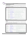
B. Basie Setting for HW
The basic settings for the HW can be set in the H file ‘H05_user/CustomerInterface.h’.
Figure 7-10: ADC Port Setting
/** UI_0301 ADC port and coefficient set */
#define MOTOR_SHUNT_NUMBER
2
// current sample resistor
#define CURRENT_RS
0.02 // Iuvw sample resistor,unit:ohm
#define Current_Amplifier_Multiple
10
// Iuvw calculation factor
#define VDC_Amplifier_Multiple
96.0
//Vdc calculation factor
#define DC_V_PIN
ADC_CH_2// Vdc sample channel
#define MOTOR_U_PIN
ADC_CH_0// Iu sample channel
#define MOTOR_V_PIN
ADC_CH_1// Iv sample channel
#define MOTOR_W_PIN
// Iw sample channel
#define IPM_TEMP_PIN
ADC_CH_3// IPM temperature sample
The Demo Board’s current sample resistor is 0.02Ω, current OP’s 10 times, DC Bus voltage sample factor is
channel
96. Relay and other GPIO settings are shown in Figure 7-11.
Figure 7-11: GPIO Port Setting
/** UI_0302 configure relay and other GPIO*/
// Relay port setting
#define RELAY_PORT PORT5
#define RELAY_PIN PIN2
// other GPIO setting
Firmware can work in debug mode to check whether the hardware works properly. This macro is defined in
CustomerInterface.h, as shown in Figure 7-12.
Figure 7-12: Function Select
/** UI_0304 Function set
#define FW_TEST_MODE
FALSE
#define DC_INPUT
310
*/
// HW\Hall check set
//TRUE: work in debug mode for testing HW and Hall
//FALSE: work in normal mode and disable Hall check
//the DC bus voltage to inverter board for test mode
The advanced functions are set at this part, if you want run the HW check function, the macro
FW_TEST_MODE can be set to TRUE to run these functions.
Feb 26, 2015, FM3_AN706-00096-1v0-E
31
U S E R
7.2.1.2
M A N U A L
Advanced Variables Setting
If the motor runs well in any working condition, the settings in this section do not need to change.
Advanced Setting for MCU
These parts are not recommended to modify for the inverter washing machine solution in the file‘H05_user/
CustomerInterface.h’
MCU Clock Setting-----The MCU on the Demo Board is MB9AF111K. The maximum machine frequency is
40MHZ.
Figure 7-13: MCU Clock Setting
/** UI_0401 MCU clock setting
#define FREQ_XTAL
#define SYS_CLOK
*/
4L // MHz
Main_Frequency_40M
A/D Converter Setting
Figure 7-14: A/D Converter Setting
/** UI_0402 A/D sample setting
#define ADC_Digit
12
#define ADC_MAX
(1 << ADC_Digit)
#define ADC_REF
5.0
#define MOTOR_ADC_FORWARD_TIME
2
#define AD_OFFEST_MAX_VALUE
#define CURRENT_NORMAL_OFFEST
#define CURRENT_OFFEST_MAX
#define CURRENT_OFFEST_MIN
Advanced Setting for FW
*/
200
//100
(1 << (ADC_Digit - 1))
(CURRENT_NORMAL_OFFEST + AD_OFFEST_MAX_VALUE)
(CURRENT_NORMAL_OFFEST - AD_OFFEST_MAX_VALUE)
These variables in this parts can be modified if the performance of corresponding module is not so good or
you want to change the setting for a different washing machine, and you can find them in the file‘S05_user/
CustomerInterface.c’.
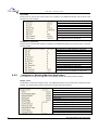
Motor Start-up and Start/stop Setting
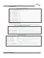
The parameter for the motor start-up and the brake stop end speed can be set in this part.
Figure 7-15: Variables Setting for Motor Running
/** UI_0201 Motor start-up variables setting */
int32_t Motor_StartSpd
= 25;
// start up drum speed,unit:rpm
float
Startup_InitCur = 0.2;
//initial startup current, unit:A
float
Startup_IncCur = 0.08;
//initial startup current, unit:A
float
Startup_SwitchCur= 0.5;
//the initial current of at close loop
//the times of Motor_CurrentMax,range 0~1, unit:A
uint16_t Startup_PreOrtTime = 100;
//pre-oriente time,unit:ms
uint16_t Startup_OrtTime = 500;
//oriente time,unit:ms
uint16_t Startup_ForceTime = 512;
//force running time,unit:ms
uint16_t Startup_StableTime = 100; //stable running time after the force
running,unit:ms
uint8_t Startup_RunLevel = CHANGE_SPEED;
32
FM3_AN706-00096-1v0-E, Feb 26, 2015
U S E R
M A N U A L
PI Parameter Setting
Figure 7-16: PI Parameter Setting
/** UI_0204 PI parameter setting*/
uint16_t PI_SPD_Doing_Cycle_Wash = 8; // 8*62.5us
uint16_t PI_SPD_Doing_Cycle_Spin = 16; // 1ms
float
PI_Spd_Kp = 5;
float
PI_Spd_Kp_Min = 10;
float
PI_Spd_Kp_Max = 55;
float
PI_Spd_Ki_Min = 0.02;
float
PI_Spd_Ki_Max = 0.5;
float
PI_Spd_Kp_Spin = 4;
float
PI_Spd_Ki_Spin = 0.02;
float
float
float
float
PI_Idq_Kp_Wash
PI_Idq_Kp_Spin
PI_Idq_Ki_Wash
PI_Idq_Ki_Spin
=
=
=
=
20.0;
10.0;
0.03;///0.03;
0.03;
uint16_t
PI_Field_Doing_Cycle
Field
Weaken
and Limitation Setting = 80;
float PI_FieldWeaken_Ki_Init = 0.02;
The minimum field weaken running current and the FOC current and voltage limit can be set in this part.
float PI_FieldWeaken_Kp_Init = 0.06;
Figure 7-17: Field Weaken and Limitation Setting
float PI_FieldWeaken_Ki_End = 0.02;
/** UI_0205 Field Weaken variables setting*/
float PI_FieldWeaken_Kp_End = 0.06;
float
FieldWeaken_IsMin = -0.05; //min current in field weak,unit:A
//IsMax = Motor_CurrentMax*Limit_IdUsage calculate on-line, unit:A
/** UI_0206 FOC limit setting */
float
Limit_VsUsage
= 1.00;
//DC voltage usage rate for FOC
float
Limit_VdUsage
= 0.98;
//d-axis voltage usage rate for FOC
float
Limit_IsUsage
= 0.95;
//d and q axis current usage rate for the FOC
float
Limit_IdUsage
= 0.8;
//d axis current usage rate in the field weaken
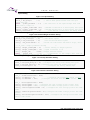
UART Setting
Figure 7-18: UART Setting
/** UI_0207 UART setting
*/
uint16_t u16Baudrate
= 2400;
// Baud rate of UART, unit:bps
char_t cParityEn
= FALSE;
// TRUE -- Parity check enable,FALSE--Disable
char_t cParitySel
= ODD_NUMBER_PARITY;//ODD_NUMBER_PARITY,EVEN_NUMBER_PARITY
uint16_t u16DataLen
= 8;
//data length, default 8bit
uint8_t u8StopBitLen
= 1;
//stop bit, default 1bit
uint8_t u8Direction
= LSB_FIRST; //bit direction
//LSB_FIRST -- low bit first,MSB_FIRST -- high bit first
uint8_t Uart_u8CommErrTime= 6;//time delay for the comm error or resume,unit:s
uint8_t Uart_u8CommDelay = 0;//time delay between Rx and Tx switch,unit:ms
// PORT and other macro setting in UART.h
Feb 26, 2015, FM3_AN706-00096-1v0-E
33
U S E R
M A N U A L
Speed Setting
Figure 7-19: Speed Setting
/** UI_0208 Speed set parameter setting
*/
int32_t Wm_SpinSpd
= 70;
// switch drum speed between wash and spin
state,unit:rpm
float
SpdSet_BaseTime = 0.1;
//the time unit of the speed change time from
UART,unit:s, range 0~1
uint16_t SpdSet_u16AcceLmt =100; //maximum acceleration of drum speed, unit:rpm/s
uint16_t SpdSet_u16DeceLmt = 20; //maximum deceleration of drum speed, unit:rpm/s
uint16_t DefaultAcce
= 50;
//the default acceleration for debug mode
OOB and Weight Setting
Figure 7-20: OOB and Weight Parameter Setting
/** UI_0209 OOB parameter setting
*/
uint16_t OOB_u16OobSpd
= 89;
//OOB detect speed
uint16_t OOB_u16OobSpd1 = 90;
//the Second OOB detect speed
uint8_t OOB_u8StableTime = 4;
//stable run time before OOB Detect stage, unit:s
/** UI_02010 weight parameter setting
*/
int16_t Weight_i16WtSpdN1 = 90;
//stable running at weight speed n1
int16_t Weight_i16WtSpdN2 = 130; //speed accelerate to n2
char_t Weight_cEn
= TRUE; //weight function enable
float
Weight_fCoe
= 7.0;
//coefficient of the weight data with DC
bus(BLDC)default acceleration for debug mode
Un-Stop Setting
Figure 7-21: Un-Stop Parameter Setting
/** UI_02011 UnStop parameter setting
*/
uint8_t UnStopCCW_EleCycle = 10; //configure the unstop CCW running ele-cycle
uint8_t UnStopCW_EleCycle = 10; //configure the unstop CW running ele-cycle
int16_t i16UnStopSpd = 45;
//configure the unstop running spd
Protection Setting
Figure 7-22: Protection Parameter Setting
/** UI_02012 protect variable setting ******/
char_t LockRotorProtectEn = TRUE;
uint32_t LockMinSpd = 10;
//configure the locked min speed: 10r/min
uint32_t LockMaxTime = 4000;
//configure the check lock max time: 4000ms
char_t DCVoltageProtectEn = TRUE;
uint16_t DCVoltageMax = 400; //configure the over voltage protect
uint16_t DCVoltageMin = 200; //configure the under voltage protect
uint32_t OverVoltageProtectTime = 50; //configure the over voltage
200ms
uint32_t UnderVoltageProtectTime = 30;//configure the under voltage
2000ms
uint32_t RecoverVoltageProtectTime = 2000; //configure the voltage
error's time 2000ms
value: 400V
value: 150V
protect max time
protect max time
back normal from
//other variable seen at corresponding part in file ‘S05_user/ CustomerInterface.c’
34
FM3_AN706-00096-1v0-E, Feb 26, 2015
U S E R
7.2.2
M A N U A L
HW Check
The HW performance can be self-checked by the HW check module.
If the HW has been used for a long time, this module can be ignored. And the motor can be normally started
as shown in section 7.2.2.3 Run Motor.
Note: The HW performance must be validated and the related FW setting must be also correctly set,
otherwise the Hall self-check and the motor may not run well.
7.2.2.1
FW Setting
Set the macro ‘#define FW_TEST_MODE TRUE’ to make the control system run as debug mode.
Set the real DC bus that is measured by multi-meter between the PN points on the HW to the macro
definition as following:
#define DC_INPUT 310
//the DC input voltage to inverter board in test mode, unit: V
7.2.2.2
HW Check Run
Click the debugger button
to connect the J-link, and paste the global structure
‘HwCheck_stcPar’ into the Live Watch in the IAR debug online.
Enable the HW check function by the variable ‘cStart’ that is shown in Table 7-1. The HW performance such
as DC sample and HW over-current point can be self-checked by this function.
Table 7-1: Global Structure for HW Check
HW check start command
HW check stop command
HW check finished flag
Flag for HW check error
Flag for DC voltage check error
Flag for current sample check error
Value of the HW over-current protection
When the HW check finished flag ‘cOver’ is set to ‘1’, the HW check result
as shown in Table 7-1.
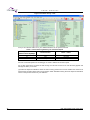
7.2.2.3
is output by the global structure
Run Motor in Normal Mode
When the setting parameter especially the
started for the demo show.
Basic Setting parameters have been finished. The motor can be
(1) Reset the FW TEST MODE macro definition in ‘H05_user/ CustomerInterface.h’ as following:
#define FW_TEST_MODE
FALSE
// HW¥Hall check set
(2) Check the basic motor and HW parameter setting in the user interfaces. If the setting does not match
with the real HW and washing machine parameter, there will be an unexpected running error in the motor
running.
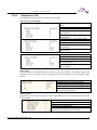
(3) Compile project and download program to inverter board by the J-link.
①Click button A that is shown in Figure 7-23 to connect the J-link and download the FW into the MCU,
②Click button B to run the FW online.
③When the relay is switched on about 2 seconds later, you can enter the none-zero speed value to start
the motor in the structure that is shown as C.
For example, when the variable ‘Motor_stcRunParam. i16WmCommandSpdRpm
input, the drum speed of the washing machine will CCW run to 90rpm.
Feb 26, 2015, FM3_AN706-00096-1v0-E
= 90’ by your online
35
U S E R
M A N U A L
Figure 7-23: Motor Run by J-link
A
D
B
C
And you can take the Table 7-2 for your detailed reference for the speed command.
Table 7-2: Drum Running Status by the Command Speed
Motor_stcRunParam.
Drum Direction
Motor’s status
i16WmCommandSpdRpm
>0
<0
CCW
CW
Running
Running
=0
Stop
Stop
Note:
All of the command speed from the debugger or UART is defined as the drum speed.
Do not click the button D to break the FW running, the HW over-current or DC over fault may appear and
damage the HW if you do that.
(4) Watch the important variable to check the motor running performance such as whether the real motor is
achieved the command speed and running speed is stable. Detailed meaning about the important variable is
shown in the previous section for your reference.
36
FM3_AN706-00096-1v0-E, Feb 26, 2015
U S E R
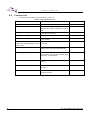
7.2.3
M A N U A L
Speed Acceleration and Deceleration
After run motor normally, you can run motor in any speed, and the type speed of the drum for front loading
washing machine can be taken for the reference at .
Table 7-3.
Table 7-3: Typical Running Status by the Command Speed
Motor_stcRunParam.
Drum
Description
i16WmCommandSpdRpm
Direction
30~50
CCW
The Drum speed runs at 30~50rpm for the wash mode
-30~-50
CW
The Drum speed runs at 30~50rpm for the wash mode
The Drum speed runs at 89rpm for the OOB detection
before the spin mode
The Drum speed runs at 400rpm for the pre-spin
89
CCW
400
CCW
100
CCW
1000
CCW
The Drum speed runs at 100rpm to drain away water by the
host after the pre-spin
The Drum speed runs at 1000rpm for the spin mode
1200
0
CCW
Stop motor
The Drum speed runs at 1200rpm for the spin mode
The motor will stop working
The default speed changing time is 10 which means 1s as shown in 7.2.1.2 Advanced Variables Setting, if
you want to change the default acceleration, you can disable the UART macro definition’ UARTEN ’ in
UART.h and set the default acceleration ‘DefaultAcce’ or the maximum acceleration ‘SpdSet_u16AcceLmt’
as you want.
When the motor needs to reverse the running direction, you should stop motor and then restart the motor to
run in another direction.
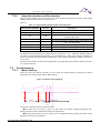
7.3 Troubleshooting
7.3.1
Motor Start-up
When the motor can’t start-up normally, you can modify the related interface to improve the start-up
performance, the reference is in section ‘Motor Start-up’
Figure 7-24: Motor Start-up Diagram
Orient
Force Run
closed loop
Stable
run
The common abnormal start-up is shown as below:
●The orient time is too long or short, you can modify the interface ‘Startup_PreOrtTime’ and ’
Startup_PreOrtTime’ till the performance meets your requirement.
●The force running time is too long or short, you can modify the interface ‘Startup_ForceTime ’ till the
performance meets your requirement.
Feb 26, 2015, FM3_AN706-00096-1v0-E
37
U S E R
M A N U A L
●The rotor speed and the phase current over-shoot greatly at the closed loop, you can modify the
interface ‘Startup_SwitchCur’ till the performance meets your requirement. The initial current at close-loop
is Startup_SwitchCur*Motor_CurrentMax, so ‘Startup_SwitchCur’ is between 0~1.
● If you want to change the force running speed at start-up, you can modify the interface
‘Motor_StartSpd’ as you want.
7.3.2
Protection
When the motor is stopped without the normal stop command, the protection fault may appear, you can see
the value of the variable ‘Motor_stcRunParam.u16FaultCode’ in the watch window and the code is assigned
by the bit OR operation. The fault code for each protection is shown as below and it is located at file
‘‘H05_user/ CustomerInterface.h’’. You can match the value with these fault codes to find which protection
happened.
#define NORMAL_RUNNING
0x0000
//no error
#define OVER_VOLTAGE
0x0001
//DC bus over-voltage
#define UNDER_VOLTAGE
0x0002
//DC bus under-voltage
#define SW_OVER_CURRENT
0x0004
//over-current
#define MOTOR_OVER_CURRENT
0x0008
//over-current of HW
#define MOTOR_LOSE_PHASE
0x0010
//motor lose phase
#define NO_CONECT_COMPRESSOR
0x0020
//no motor connected
#define AD_MIDDLE_ERROR
0x0040
//current sample 2.5V offset error
#define SF_WTD_RESET
0x0080
#define MOTOR_LOCK
0x0100
//motor lock
#define UNDEFINED_INT
0x0200
//undefined interrupt
#define HW_WTD_RESET
0x0400
//FW watch dog reset
//HW watch dog reset
#define IPM_TEMPOVER
0x1000
//IPM over current
#define COMM_ERROR
0x4000
//communicate error code
There may be different processing logic about the protection.
The fault code may not be cleared except the DC bus voltage protection for the inverter DEMO. That is the
FW may not run again when the protection fault happens. You can access the variable
‘Motor_stcRunParam.u16FaultCode’ to make your own protection processing logic.
7.3.3
Drum Direction Reversed
If running direction of the drum does not meet the requirement of washing machine, there are two
possibilities for this trouble.
The running direction of the motor is different from the belt drive washing machine. You can change the
value of this variable to make the motor run the right direction as you want.
The U V W of the motor phase is not correctly connected on the corresponding port on the HW. If the motor
phase is not correctly connected, you can change any one of the phase line with another.
7.3.4
PI Parameter
If the speed can’t be stable at the command speed, all of the PI parameters and the cycles of the PI
regulator can be modified in the ‘CustomerInterface.c’.
Each of the PI parameters can be modified on line due to the PI parameter changeable function ‘void
PID_ParameterChange(void)’ that is located in file ‘PID_Control.c’ has been masked in 1ms timer event at
file ‘Timer_Event’. The PI parameters can be fixed into this function when the PI parameters are fine tuned.
38
FM3_AN706-00096-1v0-E, Feb 26, 2015
U S E R
M A N U A L
8. Additional Information
For more Information on Spansion semiconductor products, visit the following websites:
English version address:
http://www.spansion.com/Products/microcontrollers/
Chinese version address:
http://www.spansion.com/CN/Products/microcontrollers/
Please contact your local support team for any technical question
America: [email protected]
China:
[email protected]
Europe: [email protected]
Japan: [email protected]
Other: http://www.spansion.com/Support/SES/Pages/Ask-Spansion.aspx
Feb 26, 2015, FM3_AN706-00096-1v0-E
39
U S E R
M A N U A L
9. Reference Documents
[1]. AN_104_FTDI_Drivers_Installation_Guide_for_WindowsXP(FT_000093).pdf: FTDI device driver
installation guide for Windows XP.
[2]. AN_119_FTDI_Drivers_Installation_Guide_for_Windows7.pdf: FTDI device driver installation
guide for Windows 7.
[3]. AN_234_FTDI_Drivers_Installation_Guide_for_Windows_8.pdf: FTDI device driver installation guide for
Windows 8.
40
FM3_AN706-00096-1v0-E, Feb 26, 2015
U S E R
M A N U A L
AN706-00096-1v0-E
Spansion Application Note
FM3 Family
32-BIT MICROCONTROLLER
Washing Machine 3-Phase BLDC Sensor-less FOC Control User Manual
Feb 2015 Rev. 1.0
Published:
Edited:
Spansion Inc.
Communications
Feb 26, 2015, FM3_AN706-00096-1v0-E
41
U S E R
M A N U A L
Colophon
The products described in this document are designed, developed and manufactured as contemplated for general use,
including without limitation, ordinary industrial use, general office use, personal use, and household use, but are not
designed, developed and manufactured as contemplated (1) for any use that includes fatal risks or dangers that, unless
extremely high safety is secured, could have a serious effect to the public, and could lead directly to death, personal injury,
severe physical damage or other loss (i.e., nuclear reaction control in nuclear facility, aircraft flight control, air traffic control,
mass transport control, medical life support system, missile launch control in weapon system), or (2) for any use where
chance of failure is intolerable (i.e., submersible repeater and artificial satellite). Please note that Spansion will not be liable
to you and/or any third party for any claims or damages arising in connection with above-mentioned uses of the products.
Any semiconductor devices have an inherent chance of failure. You must protect against injury, damage or loss from such
failures by incorporating safety design measures into your facility and equipment such as redundancy, fire protection, and
prevention of over-current levels and other abnormal operating conditions. If any products described in this document
represent goods or technologies subject to certain restrictions on export under the Foreign Exchange and Foreign Trade Law
of Japan, the US Export Administration Regulations or the applicable laws of any other country, the prior authorization by the
respective government entity will be required for export of those products.
Trademarks and Notice
The contents of this document are subject to change without notice. This document may contain information on a Spansion
product under development by Spansion. Spansion reserves the right to change or discontinue work on any product without
notice. The information in this document is provided as is without warranty or guarantee of any kind as to its accuracy,
completeness, operability, fitness for particular purpose, merchantability, non-infringement of third-party rights, or any other
warranty, express, implied, or statutory. Spansion assumes no liability for any damages of any kind arising out of the use of
the information in this document.
®
®
®
TM
TM
Copyright © 2014 Spansion. All rights reserved. Spansion , the Spansion logo, MirrorBit , MirrorBit Eclipse , ORNAND
and combinations thereof, are trademarks and registered trademarks of Spansion LLC in the United States and other
countries. Other names used are for informational purposes only and may be trademarks of their respective owners.
42
FM3_AN706-00096-1v0-E, Feb 26, 2015