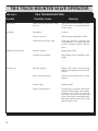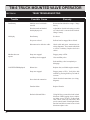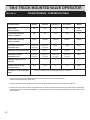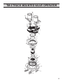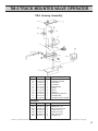
1
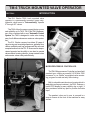
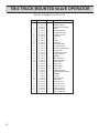
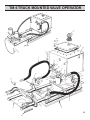
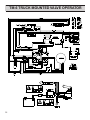
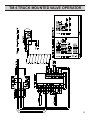
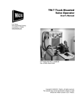
Truck Mounted Valve
Operator
Model TM-6, TM-6B
i
PIPE & VALVE
MAINTENANCE PRODUCTS
Mod. TM-6, 6B S/N:
E.H.
WachsCOMPANIES
Company
E.H.
WACHS
600 Knightsbridge
Parkway,
Lincolnshire,
100 Shepard
St. Wheeling
Il. 60090IL 60069
Part Number:
Revision No:
07-MAN-01
2
Revised:
April, 98
TM-6 TRUCK MOUNTED VALVE OPERATOR
TABLE OF CONTENTS
SECTION I
INTRODUCTION
4
SECTION II
SAFETY INSTRUCTIONS
5
SECTION III
MACHINE SPECIFICATIONS
6
SECTION IV
SET UP & OPERATION
7-10
A. TM-6 Installation Instructions
B. TM Controller
C. Operation Instructions
7-8
9
10
SECTION V
MAINTENANCE
11
SECTION VI
TM-6 TROUBLESHOOTING
14-15
TM-6B TROUBLESHOOTING
16-17
SECTION VII
OPERATION MODE COMPARISON TABLE
20
SECTION VIII
PARTS LISTS AND EXPLODED VIEW DRAWINGS
22-29
SECTION IX
WIRING DIAGRAMS AND VALVE EXCECISE LOG
32-35
SECTION X
PARTS ORDERING INFORMATION
36
TM-6 TRUCK MOUNTED VALVE OPERATOR
SECTION I
INTRODUCTION
The E.H. Wachs TM-6, truck mounted valve
operator is a permanently mounted, heavy duty,
hydraulic valve turner to "Automatically" operate
6" through 96" valves.
The TM-6 offers the same rugged design, power
and reliability as it's TM-2, TM-3, and TM-5 predecessors. Now, combined with a new "Automatic Control
System" the TM-6 is designed to make valve turning
easy for all utilities and assures maximum valve protection.
The E.H. Wachs company has taken 50 years of
valve turning and exercising experience, gathered from
utilities worldwide and has programmed this safe and
accepted method into the TM - 6. Now even the inexperienced operator has the ability to turn hard to operate
valves without knowing direction, loosen seized valves
and exercise valves safely and efficiently.
MICROPROCESSOR CONTROLLER:
The TM-6 Microprocessor Controller is a hand held
pendant type, utilizing a powerful 9.216 MHz Z180
processor to run Wachs' copyrighted valve exercising program for safe and easy valve turning.
Built in a durable cast aluminum housing which is
watertight and impact resistant, the TM-6 features a
backlit LCD display for easy visibility, day or night. It
also provides a tactile key pad for positive feel data
input.
The pendant, when not in use, is secured in a
snap-in closure at the front of the machine for easy
access.
4
TM-6 TRUCK MOUNTED VALVE OPERATOR
SECTION II
SAFETY INSTRUCTIONS
Since 1883, EH Wachs has built a reputation for quality and a commitment to consumer satisfaction. In accordance with this, Wachs must take on the added responsibility of doing our best to
assure the safest use of our equipment.
We have assembled a list of safety reminders to aid in creating the safest possible working
environment. We recommend that the precautionary steps listed there be closely observed.
Read the Following thoroughly
before proceeding
1. READ THE OPERATING MANUAL!!
4. KEEP CLEAR OF ROTATING PARTS!
Reading the setup and operating instructions prior to
beginning the setup procedures can save valuable time
and help prevent injury to operators or damage to
machines.
Keep hands, arms and fingers clear of all rotating or
moving parts. Always turn machine off before attempting any adjustments requiring contact with the machine
or it's accessories.
2. INSPECT MACHINE & ACCESSORIES!
5. SECURE LOOSE CLOTHING & JEWELRY!
Prior to machine setup physically inspect the machine
and it's accessories. Look for worn tool slides, loose
bolts or nuts, lubricant leakage, excessive rust, etc. A
properly maintained machine can greatly decrease the
chances for injury.
Loose fitting clothing, jewelry; long, unbound hair can
get caught in the rotating parts on machines. By
keeping these things secure or removing them you can
greatly reduce the chance for injury.
6. KEEP WORK AREA CLEAR!
3. ALWAYS READ PLACARDS & LABELS!
All placards, labels and stickers must be clearly legible
and in good condition. Replacement labels can be
purchased from the manufacturer.
Be sure to keep the work area free of clutter and
nonessential materials. Only allow those personnel
directly associated with the work being performed to
have access to the area if possible.
ALWAYS WEAR PROTECTIVE EQUIPMENT:
WARNING
CAUTION
Impact resistant eye protection must be worn
while operating or working
near this tool.
Personal hearing protection
is required at all times when
operating or working near
this tool.
5
TM-6 TRUCK MOUNTED VALVE OPERATOR
SECTION Iii
CAPACITY:
SPEED:
SPEED CONTROL:
DRIVE:
MICROPROCESSOR:
MACHINE SPECIFICATIONS
Operates all gate valves through 96"
5 to 30 revolutions per minute.
Speed controlled by hydraulic flow at source.
Dual, self lubricating , hydraulic motor drive to single ring gear. Balanced power load.
Pendant type. Water and shock resistant. Automatically operates valves in an exercising sequence
compatible with industry standards. LCD readout displays revolution count ( in tenths ), operating torque,
peak torque, torque limit and direction.
TORQUE:
Variable from 0 to 2500 ft/ lbs.
RETROFIT:
Retrofit available for Wachs TM-2, TM-3 and TM-5.
CONTROL VALVE:
Solenoid operated hydraulic directional control valve. On, off and direction.
DIMENSIONS:
25" wide x 51" long x 23" high. Requires 9.2 square feet of bed space.
OIL TANK:
19 gallon steel fabricated with sight guage.
FILTRATION:
10 micron canister type, easy change filter.
VALVE KEY:
2" square, high strength cold rolled tubing.
SOCKET:
2" square AWWA standard , universal type
MISALIGNMENT CAPABILITY: 12 degrees at power head.
FRAME:
Structural steel channel, fabricated.
HEAD EXTENSION:
21" from frame to center of head. 28" maximum.
WEIGHT:
370 lbs. dry weight.
FINISH:
Acrylic enamel paint ( yellow )
AUXILIARY HYD. CIRCUIT:
Integral power supply, provides 2000 psi @ 8 gpm.
WARRANTY:
1 year factory warranty against all defects in materials and workmanship
PRODUCT SUPPORT:
OEM training available on-site or at manufacturers facility.
PRODUCT LIABILITY INS.
Manufacturer shall maintain product liability.
COMMERCIALLY PROVEN:
Manufacturer shall provide, upon request, evidence that the valve operator to be furnished has been
commercially proven to the industry for not less than 1 year and replacement parts are readily available.
6
TM-6 TRUCK MOUNTED VALVE OPERATOR
SECTION IV
SET-UP AND OPERATION
A. INSTALLATION INSTRUCTIONS
1. Install a power take-off on truck transmission. See
manufacturer's instructions included with power take-off.
Be certain that rotation of power take-off shaft matches
rotation of Hydraulic Pump as indicated by arrow on pump.
PTO supplied by Wachs is normally installed on right
(passenger) side of transmission unless specified otherwise.
2. Connect PTO control cable and mount red engagement
knob assembly in desired location on dashboard. Control
should be installed so that PTO will become engaged
when pulled out.
3. The most satisfactory pump installation is direct flange
mounted onto the PTO eliminating universal joints and
drive shafts from PTO to remote mounted pump. If Wachs
supplies the pump it will be a flange mounted with splined
shaft for direct mount to PTO unless otherwise specified.
If pump is purchased by customer from other than Wachs
it must be capable of producing 14 GPM at 1200 RPM at
2000 PSI. NOTE: Do not operate pump until system is
filled with oil.
4. Set valve operator in truck at desired location. Keep as
close as possible to opening on side of body to assure
maximum reach of power head when extended. Layout
and drill eight (8) 9/16" mounting holes in truck bed for
securing unit to the truck frame. (Ref. Fig. #2, Letter C on
page 8).
5. Layout and cut two access holes in bed of truck: 1-3/8"
access hole for 1" high pressure line (ref. #2, letter D on
page 8) 2" acess hole for 1-1/4" low pressure return line
(ref. Fig. #2, Letter A on page 8). If access holes cannot
be cut beneath connecting points on machine because of
frame members, cut where clearance is available. Extra
piping from access holes to connecting points may be
needed. See Step 6.
6. Figure 3 shows suggested hose assemblies which should
be purchased. High pressure hole should be 1" two wire
braid capable of at least 1500 PSI working pressure.
Return hose should be 1-1/4" rayon braid capable of at
least 300 PSI working pressure. Hose ends should be
male pipe thread. In figure 3 we recommend the use of 1"
heavy wall pipe and 1-1/4" standard wall pipe for all
connections through bed of truck. Pipe should extend
under truck bed far enough to allow straight hose connec-
tions. Note that a swivel connection is necessary at one
end of each hose.
7. Bolt Valve Operator to truck bed using 1/2" bolts through
mounting holes (ref. #2, Letter C on page 8) cut in Step 4.
If mounting bolts do not ground operator to frame of truck,
connect ground strap from one bolt to frame.
8. Install piping and hoses assembled in Step 6. Use pipe
tape on all connections. Use one to three hose clips to
secure hose to underside of truck.
9. Connect red wire coming off of micro switch directly to
battery positive terminal. Ground, or black wire, must make
a solid connection directly to vehicle chassis ( See diagram
above). A 14 guage wire minimum should be used to make
these connections.
10. Fill tank to full mark on gauge (approximately 22 gallons).
Use hydraulic oil (Mobil, DTE light or equivalent).
11. Purchase and install hand throttle if truck is not equipped
with one.
12. Test system by engaging PTO. Allow truck to idle for
several minutes to purge air from system and check for
hydraulic oil leaks.
See OPERATING INSTRUCTIONS before proceeding
with operation.
13. Most truck body and equipment installers are familiar with
installations of the type described above. This includes
PTO, pump, hose lines and throttle controls.
14. If a door is cut in side of truck body for access to Valve
Operator make it at least 25" wide and 17-1/4" high (14"
high with direction control handle shortened) to allow power
head to slide in and out.
7
TM-6 TRUCK MOUNTED VALVE OPERATOR
SECTION IV
8
SET-UP AND OPERATION (cont.)
TM-6 TRUCK MOUNTED VALVE OPERATOR
SECTION IV
SET-UP AND OPERATION (cont.)
22. JOG RIGHT: Rotate power head right slightly.
23. LIGHT: Display light on/off.
Other controls:
1. Power Take-Off Control
The Valve Operator gets its power from the truck transmission through a hydraulic pump. Before operating a valve,
the PTO knob must be actuated to engage the power takeoff and start the hydraulic pump. Always push clutch in on
standard transmission vehicles before engaging the PTO.
2. Truck Throttle
The speed of the Valve Operator is adjusted by changing
the truck engine speed. The truck should have a lockable
throttle in the cab, either original equipment or added later.
The speed range of the Valve Operator is 5 to 30 RPM.
When the truck is idling the Valve Operator should turn
about 5 RPM.
3. Emergency Stop
The TM-6 is equipped with an emergency stop button
located on top of the encoder / counter assembly housing.
B. TM CONTROLLER
1.
2.
3.
4.
5.
6.
7.
8.
9.
10.
11.
12.
13.
14.
15.
16.
17.
18.
19.
20.
21.
TM-6 CONTROLLER PAD
LCD READOUT DISPLAY
CURRENT: Torque being applied at that moment.
HIGHEST: Highest torque required to turn valve during
cycle.
LIMIT: Indicates torque limit setting.
TORQUE LEVEL INDICATOR
BAR:Measures torque being applied.
TORQUE INDICATOR LEVEL:Indicates maximum allowable torque being applied during a cycle.
DIRECTION:Primary turning direction chosen by program.
GEARED:Valve type selected, geared or non-geared.
COUNT: Revolution counter, counts in 10th's of a turn.
MODE:Operation mode selected- exercise or emergency.
RESET COUNT: Reset counter to zero.
STOP: Stop exercise.
LIMIT: Manually increase torque.
LIMIT: Manually decrease torque.
RESET SYSTEM: Clear all data.
START: Start exercise.
VALVE TYPE: Select valve type - geared or non-geared.
MODE: Select mode - exercise or emergency.
DIRECTION: Reset direction once operation cycle has
been completed.
JOG LEFT: Rotate power head left slightly.
9
TM-6 TRUCK MOUNTED VALVE OPERATOR
SECTION IV
SET-UP AND OPERATION (cont.)
C. TM-6 OPERATION INSTRUCTIONS
The TM-6 is programmed to operate at the lowest torque required to maintain valve stem rotation. The torque limit, though
adjustable, has a factory default at 200 ft./lbs.
The exercise, or "break loose" procedure, begins with operating torque programmed at 50 ft./lbs. If this torque is not sufficient to turn the valve stem, the direction of operation will
reverse and apply torque. This procedure, the "No Assumption" method, which allows the microprocessor to determine
direction of rotation, continues uninterrupted, increasing torque
gradually, until the stem begins to turn or operating torque
reaches the factory set torque limit. If the valve has not star ted
to turn, the operator can increase the "TORQUE LIMIT" in
increments of 50 ft./lbs per operating cycle. Once the valve
stem has started turning, operating torque is reduced to the
minimum torque required to keep it turning.
The "TORQUE LIMIT" is the maximum torque the TM-6 will
apply to the valve during operation. When operating torque
reaches the TORQUE LIMIT, exercising will stop automatically. This is usually an indication that the valve is fully opened
or fully closed.
If additional torque increases are necessary, the limit may be
increased once by pressing the limit key. TORQUE LIMIT increases are available only when operating torque has reached
the TORQUE LIMIT. When operating torque drops well below
the LIMIT, the LIMIT will decrease automatically.
EMERGENCY MODE is available when a valve must be closed
in a hurry while still enforcing safe valve operation. Fewer
reverses are induced and the torque limit remains at set point.
At this point, the operator has full control of the set torque
point.
MANUAL MODE is intended for the experienced operator. The
torque set point is not in effect and operation stops only when
operating torque reaches the torque limit. No forced reverses
occur and the operator has full control of the torque limit (this
feature available only by request).
VALVE TYPE SELECTION
Geared valves require a special consideration for proper exercising. To effectively clean the stem and slides, any up and
down motions of the gate must occur through a greater number of turns than on a non-geared valve. Selecting a geared
valve type will account for this by backing up further during
temporary direction changes.
1.
2.
3.
4.
5.
When tuberculation, calcification or other deposits have built
up on the valve stem or slides, rotation may become tight,
requiring increased operating torque. The TM-6 will stop and
automatically reverse direction temporarily. This helps to flush
loosened debris from the stem threads and slides. Operation
resumes automatically with increased operating torque. (Operating torque never exceeds the factory set TORQUE LIMIT.
When rotation becomes easier and less torque is required to
turn the valve, operating torque automatically decreases to
the lowest torque needed to maintain rotation.
OPERATION MODES
Three modes are available for valve exercising with the TM-6.
EXERCISE MODE provides the safest and most thourough
valve excercising method. The torque limit may be increased
only if the current limit is insufficient to turn the valve. When
rotation becomes easier and operating torque decreases, the
limit will decrement back to its original value. This ensuresthat
the TM-6 uses only the minimum required torque.
10
6.
7.
8.
9.
10.
11.
12..
Position truck next to valve box.
Engage PTO and set engine speed.
Remove locking pins located to either side of the power
head and pull the head out over the valve.
Insert the valve key into the power head. Use the right
and left [ JOG ] keys, if necessary, to align the socket
over the valve nut.
By using the TM-6 control pad, initialize the valve turning
sequence by selecting the VALVE TYPE, either geared
or non-geared, to be turned.
Select the MODE of operation. Choose from emergency
or exercise.
Press the [ START ] button to begin exercise. Exercise
will automatically stop when operating torque reaches
the TORQUE LIMIT.
If TORQUE LIMIT has been reached and valve has not
yet started to move, the control pad will flash the
"insufficient torque" message. At this time the TORQUE
LIMIT may be adjusted by using the limit keys.
When machine stops, check COUNTER to determine if
the valve has reached the full open or full closed position.
Press the [ DIRECTION ] and the [ START ] buttons to
exercise the valve in the opposite direction.
When complete, use the [ JOG ] keys, if necessary, to
release the valve key and remove it from the valve nut.
Remove the valve key from the power head and slide it
back into truck until locking pins can be replaced. Once
head is secured, disengage PTO and move onto next
valve.
TM-6 TRUCK MOUNTED VALVE OPERATOR
SECTION V
MAINTENANCE
Routine:
1. Keep slide bars greased to prevent rust and facilitate easy
sliding of power head.
A. Change hydraulic filter on tank once a year – replacement filter can be purchased from WACHS.
2. Use a soft automotive grease in gear box, applied at grease
fitting.
B. Change hydraulic oil (Mobil, DTE light or equivalent)
every two years. Note tank drain (ref. Fig. #2, Letter B).
3. Check oil level on gauge of hydraulic oil tank. Add oil if
necessary. Keep hydraulic oil level at full mark on gauge.
5. No lubrication attention is required on the two hydraulic
motors as they are adequately lubricated by the hydraulic
oil.
4. Oil temperatures should not exceed 180° F under prolonged or hard operating. If this temperature is exceeded,
the hydraulic oil will break down and damage pump. The
ample storage tank on the Wachs valve operator should
assure proper oil temperature under normal conditions. If
excessive temperatures are encountered, check oil level.
If reservoir is full and high oil temperatures continue
consult E.H. WACHS CO.
6. Check ALL electrical connections regularly.
For problems other than these, refer to Trouble Shooting
section or call the E.H. WACHS COMPANY at 1-800/3238185.
ACCESSORIES:
POWER TAKE-OFF (PART NO. 07-401-00)
2 gear type, extra heavy duty to accept flange mounted
hydraulic pump. Customer to provide truck model, year and
transmission model when ordering.
HYDRAULIC PUMP (PART NO. 07-402-00)
To supply power for Truck Mounted Valve Operator. Customer
to specify either flange mount for direct mount to PTO listed
above or foot mount for remote mounting and connection
through Universal Joint and shaft to customer's PTO.
AUXILIARY POWER PACKAGE (PART NO. 07-404-00)
Consisting of Pressure Relief Valve, Shut-Off Valve and piping;
installed on Truck Mounted Valve Operator to provide power for
auxiliary hydraulic equipment such as the Wachs Pump and
Portable Valve Actuator.
THROTTLE CONTROL (PART NO. 07-405-00)
Locking "T" handle type for controlling truck engine speed.
EXTRA VALVE KEYS (PART NO. 07-406-00)
Heavy-duty 2" square keys drilled both ends to accept socket
or key adaptor. Customer to specify length desired.
KEY ADAPTOR (PART NO. 07-407-00)
Male union for joining keys including two detent pins.
EXTRA UNIVERSAL SOCKET (PART NO. 07-408-00)
2" square ductile iron socket to fit Wachs 2" square keys and
standard A.W.W.A. nut.
EXTRA FILTER ELEMENT (PART NO. 07-139-00)
11
TM-6 TRUCK MOUNTED VALVE OPERATOR
Section VI
TM-6 / TM-6B
TROUBLE SHOOTING
13
TM-6 TRUCK MOUNTED VALVE OPERATOR
SECTION VI
Trouble
TM-6 TROUBLESHOOTING
Possible Cause
Remedy
Dead battery.
Head retracted and latched but display
stays on.
Adjust Micro Switch in housing to switch
off when head is retracted and latched.
Charge battery.
No display.
Dead battery.
See above.
No power to head.
Pull out head to engage Micro Switch.
Disconnected or defective cable.
Check cable and power connections (see
wiring diagrams). Test control cable leads
to insure continuity. Replace defective
cables.
Pump not engaged.
Engage pump or PTO.
Auxilliary circuit engaged.
Push auxilliary valve in completely to disengage.
Pump not engaged.
Engage pump or PTO. Verify drive hub
rotation by pressing JOG keys in both directions.
Poor electrical connection.
Check electrical connections (see wiring
diagram).
Encoder failure.
Replace Encoder.
Defective Solenoid Valve.
Using JOG keys, rotate drive hub in both
directions. While jogging, observe indicator lights on top of valve. If either light
fails, check electrical connections and
power control board. If both lights illuminate but head fails to rotate in one or both
directions replace valve.
Machine does not operate.
Encoder error.
14
TM-6 TRUCK MOUNTED VALVE OPERATOR
SECTION VI
Trouble
Encoder Error
TRANSDUCER ERR displayed.
EMERGENCY STOP ERR displayed.
Low Power.
TM-6 TROUBLESHOOTING (cont.)
Possible Cause
Remedy
Relay failure.
Replace Relay.
Defective control unit.
Replace or return for service.
Damaged Cable.
Replace Cable.
Poor electrical connection.
Check electrical connections (see wiring
diagram).
Pressure transducer failure.
Check transducer voltage output at
green wire.Voltage should read
between .5 and 5V. Replace if not
within tolerance.
Defective control unit.
Replace or return for service.
Damaged Cable.
Replace Cable.
Electrical noise.
Turn off vehicle accessories.
Defective Relay.
Replace Relay.
Defective Control Unit.
Replace or return for service.
Damaged Encoder.
Replace Encoder.
Poor electrical connection.
Repair connection. Make sure proper
installation procedure was followed.
15
TM-6 TRUCK MOUNTED VALVE OPERATOR
SECTION VI
Trouble
Dead battery
No display
Machine does not
operate
TM-6B TROUBLESHOOTING
Possible Cause
Remedy
Machine stored with head e
xtended.
Retract and latch head for storage. Charge
battery.
Head retracted and latched
but displaystays on.
Adjust Micro Switch in housing to switch
off when head is retracted and latched.
Charge battery.
Dead battery.
See above.
No power to head.
Pull out head to engage Micro Switch.
Disconnected or defective cable.
Check cable and power connections (see
wiring diagrams). Test control cable leads
to insure continuity. Replace defective
cables.
Pump not engaged.
Engage pump or PTO.
Auxilliary circuit engaged.
Close auxilliary valve.
Push auxilliary valve in completely to
disengage.
COUNTER ERR displayed.
16
Blown fuse.
Replace fuse (see Kohler engine manual)
Pump not engaged.
Engage pump or PTO. Verify drive hub
rotation by pressing JOG keys in both directions.
Poor electrical connection.
Check electrical connections (see wiring
diagram).
Encoder failure.
Replace Encoder
Defective Solenoid Valve.
Using JOG keys, rotate drive hub in both
directions. While jogging, observe indicator lights on top of valve. If either light
fails, check electrical connections and
power control board. If both lights illuminate but head fails to rotate in one or both
directions replace valve.
TM-6 TRUCK MOUNTED VALVE OPERATOR
SECTION VI
Trouble
COUNTER ERR displayed.
TRANSDUCER ERR displayed.
BYPASS ACTV displayed.
TM-6B TROUBLESHOOTING (cont.)
Possible Cause
Remedy
Power control board failure.
Unplug and replace power control
board.
Damaged cable.
Replace Cable.
Defective control unit.
Replace or return for service.
Poor electrical connection.
Check electrical connections (see
wiring diagram).
Pressure transducer failure.
Check transducer voltage output at
green wire.Voltage should read
between .5 and 5V. Replace if not
within tolerance.
Defective control unit.
Replace or return for service.
Damaged Cable.
Replace Cable.
Electrical noise.
Power Control Board failure.
Press STATRT. If message clears
problem is false signal caused by
electrical noise. Consult your factory
representative if problem persists.
Unplug and replace Power Control
Board.
Replace or return for service.
Defective Control Unit.
17
TM-6 TRUCK MOUNTED VALVE OPERATOR
Section VII
OPERATION
MODE
COMPARISON TABLE
19
TM-6 TRUCK MOUNTED VALVE OPERATOR
SECTION VII
OPERATION MODE COMPARISON TABLE
Operation Mode
Exercise
Exercise
Emergency
Emergency
Manual
Valve Type
(Geared Yes/No)
No
Yes
No
Yes
Not
Available
Torque limit increases
always available?
No
No
Yes
Yes
Yes
Torque limit increment
(when available)
50 ft-lb
100 ft-lb
100 ft-lb
100 ft-lb
100 ft-lb
Automatic torque limit
decrement rate*
50 ft-lb. per
0.5 turns
50 ft-lb. per
1.5 turns
None
None
None
50 ft-lb.
50 ft-lb.
100 ft-lb.
100 ft-lb.
None
50 ft-lb. per
0.5 turns
50 ft-lb. per
1.5 turns
50 ft-lb. per
0.5 turns
50 ft-lb. per
1.5 turns
None
2
2
1
1
1
0.5/3
1.5/10
0.5
1.5
None
Automatic set point increment
Automatic set point
decrement rate**
Attempts required at each
set point
Number of turns during
forced reverse***
Condition to require operator
input
Set point reaches limit and 'attempts required' is satisfied.
* Limit will decrement if the difference between limit and set point is more than two set
point increments (exercise mode only).
** Set point will decrement if the difference between set point and operating torque is more than 100 ft-lb.
*** In exercise mode, when set point is less than limit, reverses are short and intended only to clear valve nut and stem
threads (first number shown above applies). In emergency mode, all reversing is intended only to clear valve nut and
stem threads.
20
TM-6 TRUCK MOUNTED VALVE OPERATOR
Section VIII
PARTS LISTS
AND
EXPLODED VIEW
DRAWINGS
21
TM-6 TRUCK MOUNTED VALVE OPERATOR
TM-6 Head Assembly
REF.
1
2
3
4
5
6
7
8
9
10
57
78
79
PART NO.
70-001-00
70-002-00
07-003-00
07-005-01
07-006-01
07-006-02
07-009-00
07-036-00
07-037-00
07-100-00
07-072-00
07-008-00
07-018-00
QTY.
1
4
1
1
1
1
1
1
1
1
2
2
2
DESCRIPTION
GEAR HUB
DRIVE PIN
DRIVE HUB
GEAR BUSHING
UPPER THURST WASHER
LOWER THRUST WASHER
BULL GEAR
TOP HOUSING
BOTTOM HOUSING
RETAINING RING
MOTOR, HYDRAULIC
GEAR, PINION
RETAINING RING
DESCRIPTION
FASTENERS
22
REF.
PART NO.
QTY.
01
02
03
04
05
06
07
08
037
069
90-056-03
90-060-06
90-070-07
90-070-17
90-070-12
90-070-25
90-095-02
90-500-03
90-092-12
90-062-07
4
8
6
6
4
4
4
1
8
8
PIN, DOWEL 1/4 x 3/8
SHCS,5/16-18 x 5/8
SHCS, 3/8-16 x 314
SHCS, 3/8-18 x 1-3/4
SHCS, 3/8-16 x 1-1/4
SHCS, 3/8-16 x 2-1/2
HEX NUT, 1/2-20
GREASE FITTING 1/8 N.P.T.
BHCS1/2-13 x 1-1/4
5/16-18 x 1/2 BHCS
TM-6 TRUCK MOUNTED VALVE OPERATOR
23
TM-6 TRUCK MOUNTED VALVE OPERATOR
TM-6 Manifold Assembly
REF.
PART NO.
QTY.
11
12
13
14
15
16
17
18
19
20
21
22
07-085-00
07-169-00
07-172-00
07-171-00
07-170-00
07-173-00
07-174-00
07-089-00
07-090-00
07-176-00
11-004-00
62-138-00
1
1
1
1
1
3
1
1
1
1
1
18
DESCRIPTION
WIRE NUT
MANIFOLD
VALVE
TRANSDUCER
RELIEF CARTRIDGE
HOSE
HOSE
HOSE, PRESSURE N/S
HOSE, RETURN N/S
CONNECTOR
CONNECTOR CORD
TUBING 3/8"
FASTENERS
24
REF.
PART NO.
QTY.
DESCRIPTION
09
010
011
012
013
014
015
016
017
018
019
020
021
022
90-050-15
90-060-32
90-059-62
90-218-54
90-218-59
90-238-51
90-238-72
90-501-08
90-501-11
90-501-39
90-901-01
90-901-02
90-901-03
90-901-04
4
3
5
1
1
1
1
1
3
3
3
2.5FT
2.5FT
2.5FT
SHCS, 1/4-20 x 1-1/2
SHCS, 5/16-18 x ~1 /4
PLUG, NPT 1/4
EL w/SWVL 3/4-90
NIPPLE 3/4 x 6 HP
ELBOW w/ SWVL 1 ‘-90
NIPPLE, 1 x 6-1/2 LP
TERMINAL #8 BLU N/S
TERMINAL #6 RED N/S
TERM INAL #8 RED N/S
WIRE 18 GA RED N/S
WIRE 1 8GA BLACK N/S
WIRE GA BLUE N/S
WIRE 18GA YELLOW N/S
TM-6 TRUCK MOUNTED VALVE OPERATOR
TM-6 Housing Assembly*
REF.
PART NO.
QTY.
23
24
25
26
27
28
29
30
31
80
07-050-00
07-093-00
07-106-00
07-177-00
07-178-00
07-179-00
07-180-00
07-195-00
62-137-00
07-182-00
1
1
1
1
1
2
1
1
1
1
FASTENERS
REF.
PART NO.
023
024
025
026
027
028
90-009-01
90-016-56
90-020-06
90-040-03
90-045-03
90-049-01
QTY.
3
1
4
4
4
6
DESCRIPTION
PINION COUNTER
ENCODER
PLATES/N
ENCLOSURE
PANEL
RELAY
PIGTAIL
EMERGENCY SWITCH
CONNECTOR
CONTROL PAD HOLDER
DESCRIPTION
RHMS 6-32 x 1/4
ROLL PIN 3/32 x 5/8
SHCS 8-32 x 5/8
SHCS 10-24x3/8
NUT, HEX 10-24
SCREW 3/16
*NOTE: If your Valve Excerciser has been upgraded to a TM-6B or a TM-6DT, please also refer to pages 26-27 which is a supplement to this page.
25
TM-6 TRUCK MOUNTED VALVE OPERATOR
TM-6 B UPGRADE (07-307-01, 02)
26
REF.
PART NO.
QTY.
2
3
11
14
15
23
31
n/s
33
34
35
36
37
38
39
40
41
42
43
n/s
n/s
46
47
48
49
50
51
52
53
54
55
56
57
n/s
n/s
07-050-00
07-093-00
07-182-00
17-304-00
62-137-00
90-016-56
07-106-00
07-198-00
07-209-00
07-210-00
07-224-00
07-211-00
07-212-00
07-214-00
07-215-00
07-216-00
07-217-00
07-218-00
07-219-00
07-220-00
07-221-00
07-222-00
07-223-00
11-004-00
17-028-00
17-029-00
17-030-00
17-032-00
17-033-00
90-001-06
90-050-07
90-051-05
90-059-25
90-501-39
90-901-09
1
1
1
1
1
1
1
1
1
2
1
1
1
1
1
1
2
1
1
1
1
0.5
2
2
1
4
1
1
1
3
4
4
4
2
1
DESCRIPTION
PINION,COUNTER
ENCODER,PHOTOCRAFT
STAND
TMC2CONTROLLER
CONNECTOR, 3/8x90
PIN,ROLL,3/32 X 5/8
PLATE,S\N
TAG
HANDLE
STAND-OFF
ENCLOSURE,MOD
PLUG,ENCLOSURE
BRACKET,ENCODERMTG
SWITCH,MOD
PUSHBUTTON,E-STOP
BLOCK, CONTACT
GROMMET
SEAL,ENCODER
O-RING,ENCODER
HOLDER,FUSE
FUSE, 6 AMP
CORD,POWER
STRIP, FOAM
CONNECTOR,CORD
BOARD, POWER CONTROL
GROMMET
BATTERY
CABLE, CONTROL
GRIP, CABLE
SHCS,6-32 x 5/8
SHCS,1/4-20 X 3/4
HHCS,1/4-20 X 1/2
RHMS, 1/4-20 x 1/2
TERM #8 RED FORK
WIRE, 18GA WHITE
TM-6 TRUCK MOUNTED VALVE OPERATOR
27
TM-6 TRUCK MOUNTED VALVE OPERATOR
SECTION IX
REF
18
19
32
33
34
35
36
37
38
39
40
41
42
43
44
45
46
47
48
49
50
51
52
53
54
55
56
57
58
PART NO
07-089-00
07-090-00
07-020-00
07-023-00
07-024-00
07-025-00
07-029-00
07-045-00
07-055-00
07-056-01
07-057-00
07-150-00
07-406-08
07-034-00
07-035-00
07-134-00
14-124-00
14-125-00
07-062-00
07-139-00
07-041-00
07-046-00
07-140-00
07-143-00
07-142-00
07-008-00
07-018-00
07-072-00
07-304-00
TM 6 PARTS LISTS & EXPLODED VIEW DRAWINGS
QTY
DESCRIPTION
1
1
1
2
18
1
1
4
1
1
1
1
1
2
1
2
1
1
1
1
1
1
1
1
36"
1
2
2
1
HOSE, PRESSURE
HOSE, RETURN
BASE, SLIDING
PIN, SLIDE LOCKING
WIRE, RETAINING
PLATE HP HOSE
FILTER ASSEMBLY
SLEEVE, RETAINING WIRE
PLATE VALVE MOUNTING
TANK ASSEMBLY
FRAME ASSEMBLY
CRATE SHIPPING
8" VALVE KEY
UNIVERSAL SOCKET
CENTER BLOCK
UNIVERSAL SOCKET PIN
FILLER CAP ASSEMBLY
OIL LEVEL GUAGE
TANK GASKET
FILTER CANISTER
SWITCH, MICRO
CLAMP, CABLE
FUSE HOLDER
5 AMP FUSE
POWER CORD
GEAR PINION
RETAINING RING
HYDRAULIC MOTOR
*CONTROL PAD ASSEMBLY*
1
1
4
2
2
2
2
4
4
10
8
2
1
1
1
1
1
1
ELBOW W/ SWIVEL 3/4"-90°
ELBOW W/ SWIVEL 1"-90°
SSS 1/4-20 x 1/4
PIN, FAST 3/8 x 2-7/8
HHCS 1/4-20 x 1"
HEX NUT 1/4-20
LOCK WSHR SPLT RING 1/4"
BHCS 3/8-16 x 3/4
NUT, HEX 3/8-16
BHCS 1/2-13x1
BHCS 1/2-13 x 1-1/4"
NUT HEX 3/8-16
NIPPLE, CLOSE 3/4 LP
PLUG SQUARE HEAD 3/4
ELBOW 3/4-90"
NIPPLE CLOSE 1"LP
NIPPLE 1x2-1/2"
ELBOW 1"-90
FASTNERS
012
014
029
030
031
032
033
034
035
036
037
038
039
040
041
042
043
044
90-218-54
90-218-51
90-054-02
90-079-21
90-051-01
90-055-01
90-055-52
90-072-07
90-075-01
90-092-10
90-092-12
90-095-01
90-218-01
90-218-05
90-218-07
90-238-01
90-238-02
90-238-05
*CONTROL PAD CONTAINS NO USER SERVICEABLE COMPONENTS.
28
REF
PART NO
QTY
045
046
047
048
049
050
051
052
066
067
068
90-208-51
90-501-06
90-501-00
90-501-11
90-501-37
90-501-39
90-901-05
90-901-06
90-238-52
90-218-17
90-075-53
2
1
1
1
4
2
2
2
1
1
1
DESCRIPTION
ADAPTOR 5/8 x 5/8 JIC
TERMINAL 1/4" MALE
FEMALE, SPADE .250
TERMINAL #6 RED
TERMINAL #6 RED
TERMINAL #8 RED
WIRE 14 GA. RED
WIRE 14 GA. BLACK
1" ST. EL W/ SWIVEL
3/4" x 90° ELBOW
3/8" FLAT WASHER
TM-6 TRUCK MOUNTED VALVE OPERATOR
29
TM-6 TRUCK MOUNTED VALVE OPERATOR
Section IX
WIRING DIAGRAMS
AND
VALVE EXCERCISING
LOG
31
TM-6 TRUCK MOUNTED VALVE OPERATOR
32
TM-6 TRUCK MOUNTED VALVE OPERATOR
33
TM-6 TRUCK MOUNTED VALVE OPERATOR
VALVE EXERCISING LOG
VALVE
LOCATION
34
VALVE
SIZE
DEPTH
GATE
POSITION
OPEN TO
LEFT OR RIGHT
NUMBER
OF TURNS
DATE OPERATED
COMMENTS
TM-6 TRUCK MOUNTED VALVE OPERATOR
VALVE EXERCISING LOG
VALVE
LOCATION
VALVE
SIZE
DEPTH
GATE
POSITION
OPEN TO
LEFT OR RIGHT
NUMBER
OF TURNS
DATE OPERATED
COMMENTS
35
TM-6 TRUCK MOUNTED VALVE OPERATOR
SECTION X
ORDERING INFORMATION
ORDERING
To place an order or to get more detailed information on any E.H. Wachs products, call us at:
1-800-323-8185.
ORDERING REPLACEMENT PARTS
Please use parts list provided in manual. Have part description and part number of required replacement
part or parts to help expedite order and insure proper parts are being ordered.
REPAIR INFORMATION
Please call E.H. Wachs Company prior to returning any equipment for repair. We will advise you of shipping
and handling. Please enclose with equipment to be repaired your name, address, phone number and a brief
description of problem or work to be done or estimated.
All repair work done at our plant will be estimated and the customer advised of cost and time required to
complete repair.
WARRANTY INFORMATION
Enclosed with the manual is a warranty card. Please fill out the registration card and return to E.H. Wachs.
Retain the owners registration record and warranty card for your information.
RETURN GOODS ADDRESS
E.H. Wachs Company
E.H. Wachs Company
600 Knightsbridge Parkway
100 Shepard Street
Lincolnshire, IL 60069
Wheeling, Illinois 60090
PIPE & VALVE
MAINTENANCE PRODUCTS
Mod. TM-6, 6B S/N:
E.H.
WachsCOMPANIES
Company
E.H.
WACHS
600 Knightsbridge
Parkway,
Lincolnshire,
100 Shepard
St. Wheeling
Il. 60090IL 60069
847-537-8800
FAX: 847-520-1147 • 847-520-1168
Toll-Free: 1-800-323-8185
36