1
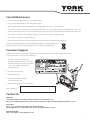
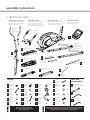
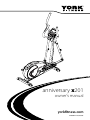
anniversary x201
owner’s manual
yorkfitness.com
VERSION II - 28/05/2007
Congratulations
on purchasing a
cross trainer from
York Fitness.
You have chosen a high quality, safe and
innovative piece of equipment as your
training partner and we are certain it
will keep you motivated on the way to
achieving your personal fitness goals.
Please take the time to read this owner’s
manual as it will help you to get the most
out of your new cross trainer. For more
information visit www.yorkfitness.com
2
contents
safety information
04
customer support
05
assembly instructions
06
user instructions
11
- quick start
- console display and feedback
- button functions
- using workout programs
exercising with your cross trainer 13
cross trainer features explained 14
how to take care of your cross trainer 15
troubleshooting
15
your warranty
16
exploded diagrams and parts list
17
3
safety information
PLEASE READ THIS INSTRUCTION MANUAL BEFORE YOU BEGIN ASSEMBLY. GREAT
CARE HAS BEEN TAKEN TO DESIGN THESE INSTRUCTIONS AND FOLLOWING THEM
WILL HELP YOU WITH QUICKER ASSEMBLY AND MINIMISE THE RISK OF INJURY
YOU ARE RESPONSIBLE FOR YOUR OWN SAFETY THIS LIST IS NOT EXHAUSTIVE.
• Always assemble and operate
the product on a level surface
• Never overload the equipment – the maximum
user weight of this cross trainer is 125kg.
• Always use the product on a level surface,
ensure that the product is stable before use.
• Never use the equipment in any other manner other
than the ways explained in these instructions and/or
any wall-chart supplied.
• Always ensure that the equipment has adequate space
on each side and front (the back can be near to a wall).
• The safety level of this equipment can only be maintained
only if it is regularly examined for wear and tear.
• Replace defective components immediately, and/or
keep the equipment out of use until it is repaired.
• Use only the adjustment settings as described in the
instructions. Always use the correct adjustment pin/fixing.
• Always check that any pins / fixings are tight and
secure before use and / or after adjustment.
• Never leave any adjustment devices
projecting from the product.
• Always consult your doctor before
undertaking any exercise program.
• Always wear suitable clothing and footwear
e.g. tracksuit / shorts / training shoes
• Remove all personal jewellery before exercising.
• Ensure you warm-up well before using the
equipment as this will help to prevent muscle strain.
• After eating, allow 1-2 hours before exercising as
this will help to prevent muscle strain.
• Injuries to health may result from incorrect or
excessive training.
• Parents and others in charge of children should be aware
of their responsibility, because the natural play instinct
and the fondness of experimenting of children can lead to
situations and behaviour for which the training equipment
is not intended
• If children are allowed to use the equipment,
their mental and physical development and above all
their temperament should be taken into account. They
should be controlled and instructed in the correct use
of the equipment.
• The equipment is under no circumstances
suitable as a children’s toy.
• Children should not be allowed on, or around
the equipment - especially when it is not in use.
• This appliance is not intended for use by persons
(including children) with reduced physical, sensory or
mental capabilities, or lack of experience and knowledge,
unless they have been given supervision or instruction
concerning use of the appliance by a person responsible
for their safety.
Safety Standards
This cross trainer meets the requirements of the EU’s EMC and Low Voltage directives (where applicable),
ISO 20957 parts 1 and 9 and AS 4092-1993. Therefore the product carries the following marks:
This product is not suitable for therapeutic purposes.
!
4
It is important that you keep these instructions for future reference.
Care & Maintenance
• Always place the equipment in a dry environment.
• Use a warm, damp cloth to keep the product clean.
• No wet cleaning of electrical components, unplug before any care and maintenance
• The safety level of the equipment can be maintained only if it is regularly examined for damage and wear. This
includes any ropes, pulleys, nuts, bolts, moving parts, bushes, chains, wheels, bearings & connection points etc
• Ensure that you inspect the product regularly - at least once a week is recommended.
• Ensure that all fixings are tight before use.
• Always replace damaged / worn components with original parts from the manufacturer.
Protect the environment by not disposing of this product with household waste.
Check your local authority for recycling advice and facilities (Europe only).
Customer Support
Should you require any assistance regarding this product please gather the following information,
and then contact us using the details below:
1. serial no. - this can be found on
the sticker below, located as indicated.
For future reference, please write down
your serial number in the space
provided below.
2. Original purchase date
3. Place of purchase
4. Information about the place
and conditions of use
5. Precise description of the issue/defect
Your Serial No. is:
Contact Us
ENGLAND
York Barbell (UK) Ltd. York Way, Daventry, Northants, England NN11 4YB
Tel: (01327) 701800 Helpdesk Tel: (01327) 701824 Fax: (01327) 706704 email: [email protected]
AUSTRALIA
Unit 1, Lot 2, Swaffham Road, Minto, N.S.W. 2566 Australia
Tel: (02) 9603 8333 Fax: (02) 9603 8555 email: [email protected]
OTHER LOCATIONS
Please see website - www.yorkfitness.com
5
assembly instructions
1. Before you start
1. Prepare your work area it is important you assemble
the product in a clean and
uncluttered space.
2. Work with a friend we recommend you have
someone assist you with
the assembly as some of the
components are quite heavy.
Upper
moving
handle bar
x2
3. Open the carton checking any warnings on
the carton and make sure you
have it the right way up.
4. Unpack the carton
Make sure you have
the following parts:
Front handle
bar x 1
Part
No.
51
Console x 1
Footplates
mount tube &
lower moving
handlebar x 2
Left footplate
36 x 1
Part
No.
Part
No.
22
Front post
x1
Part
No.
21
Right footplate
26 x 1
Part
No.
Part
No.
Foot plate
bracket x 2
Front stabilizer x 1
Part
No.
Part
No.
Pivot rod x 1 38
Rear stabilizer x 1
Part
No.
13
5
105
Adapter x 1
Fixings
20mm
head
8 allen
bolt
Part 52mm
No.
9 carriage
bolt
Part
No.
x4
Large
17 plastic
cap
Part Large
No.
20 flat
washer
Part
No.
Small
23 spring
washer
Flat
10 washer
x 14
Part
No.
Spring
11 wahser
x 16
Part
No.
Nylock
12 nut
x4
Part
No.
!
6
x2
Part
No.
Part
No.
45mm
head
59 allen
bolt
x4
Part
No.
50mm
27 carriage
bolt
Part Small flat
No.
28 washer
Tools and
Consumables
x2
Part
No.
Small
29 plastic
cap
x4
Part
No.
15mm
60 allen head
bolt
x 10
x2
Part
No.
Hand
32 wheel
x4
Part
No.
Flat
61 washer
x4
x4
Part
No.
Pull
44 plunger
x2
Spring
100 washer
x2
106
x4
Part
No.
Foot plate
45 mount
insert
x4
20mm
101 hex head
bolt
x2
Part Screwdriver
No.
107 & allen key
Spring
49 washer
x4
x4
This cross trainer takes up
a floor space of 136cm by 65cm
and weighs 42 kg
Part
No.
!
Part
No.
Part
No.
Part Large flat
No.
104 wahser
Multi spanner
58 (10,13, 14, 15mm)
x2
Part
No.
Part
No.
Allen key
x2
If you suspect you may have some parts missing, please contact
us before going back to your retailer. Refer to the Customer
Support section on page 5 for contact details.
2. Attach the stabilisers
FIXINGS:
1. Attach the front and rear stabilisers with the nuts, bolts and
washers as shown in the diagram
Part
No.
29
2. Be sure to fit the parts in the same order as the diagram
!
Check the bolts are fully tightened by making
sure they penetrate through the top of the nut
x4
Part
No.
12
x4
Part
No.
11
x4
Part
No.
10
29
12
11
10
29
12
11
10
29
12
11
10
29
12
11
10
x4
Part
No.
9
x4
9
9
3. Attach the front post
FIXINGS:
1. Connect the computer cables as shown
Part
No.
2. Slide the front post tube over the front post mounting
3. Secure in place using the bolts and washers as shown – be sure to fit them in the same order as the diagram
60
x4
Part
No.
11
x4
Part
No.
10
60
!
11 10
10
11
x4
60
Make sure the bolts are fully tightened
with the allen key
7
4. Attach the upper moving handlebars
FIXINGS:
1. Slide the pivot rod inside the tube on the front post as shown
Part
No.
2. Slide the left and right upper moving arms over this pivot rod
17
x2
3. Secure in place using the bolts and washers as shown
Part
No.
101
x2
Part
No.
100
x2
Part
No.
20 100
101
17
20
x2
17 101
100 20
5. Attach the footplates
FIXINGS:
1. First attach the support bracket to the side of the
mount tube
Part
No.
60
2. Then attach the footplates to the top of the mount
tube using the bolts and washers shown
x6
Part
No.
11
27
x6
Part
No.
10
45
x6
Part
No.
27
x4
Part
No.
45
x4
Part
No.
11
28
23
32
28
Part
No.
10
60
23
x4
x4
Part
No.
32
8
x4
6. Attach the footplates mount tube
FIXINGS:
1. Remove the bracket at the back of the footplate mount tube (keep these nuts and bolts safe as you’ll
need them to re-attach it later on)
Part
No.
10
2. Attach the same bracket to the crank arm using the fixing shown
x4
3. Re- attach the footplate mount tube to the bracket using the nuts and bolts you previously removed
Part
No.
12
4. Complete this for both sides
x2
Part
No.
37
x2
37
Part
No.
10
8
x2
Part
No.
11
10
12
Part
No.
104
8 11
x2
x2
104
7. Connect the upper and lower moving handlebars
1. Slide the lower moving handlebar up
into the tube of the upper moving
handlebar
FIXINGS:
Part
No.
44
2. Choose a height adjustment hole
and secure in position with the pull
plunger
x2
3. Repeat for the other side, making sure
to choose the height adjustment hole
in the same position
44
9
8. Attach the front handle bar
FIXINGS:
1. Secure the front handle bar to the front post
via the fixing bracket using 4 x carriage bolts,
4 x spring washers and 4 x curve washers
Part
No.
59
x4
Part
No.
49
x4
Part
No.
59
9. Attach the computer
49
61
61
59
x4
49
61
FIXINGS:
1. Connect the middle wire, that comes out of the front post, to the
computer plug on the back of the computer console
Part
No.
52
2. Secure onto the bracket using screws as shown - (screws are
located in the back of the console)
x4
3. Plug the hand pulse sensor into the right side socket on the back
of the computer
52
Final Checks
Your cross trainer is now assembled. Please make the following final checks before you use it for the first time.
Make sure all screws / bolts are tightened
Make sure you have positioned it on a flat, level surface
•
•
Power up
1. Plug one end of the adaptor into your cross trainer as shown
2. Plug the other end into a suitable AC outlet (220 – 240v – 50Hz)
10
user instructions
Quick Start
1. Make sure the cross trainer is plugged in
2. Press the ‘start / stop’ button
3. Begin pedalling
4. Adjust the resistance level with the scroll wheel
5. The values of time, distance and calories will start counting upwards
Console Display and Feedback
Profile window
Displays resistance level in manual
mode and program profile in program
mode
Calories
Approximate calories burned this
session (for comparison only, not to
be used for medical purposes); default
counts up from zero, but counts down if
a target has been set
RPM / Speed
Switches between revolutions per
minute (RPM) or current speed you are
cycling at, in km/h
Time
Time exercised this session; default
counts up from zero, but counts down if
a target has been set
Pulse
Current heart rate in beats per minute
(bpm)
Screen Display
Distance
Distance travelled this session; default
counts up from zero, but counts down if
a target has been set
Button Functions
Pre – workout
mode / enter
(push down on scroll wheel)
D
uring workout
Confirm settings
scroll wheel clockwise
scroll upwards through
setting values
increases the resistance level
scroll wheel anti-clockwise
scroll downwards
through setting values
decreases the resistance
level
enter the fitness test program
– use when your workout has
ended
fitness test
reset
reset current value, press and
hold for total reset
return to main menu
start / stop
start your workout
pauses your workout – press
again to re-start
11
Using Workout Programs
When you turn the cross trainer on it will
enter the ‘main menu’ mode, awaiting you to
select a program and begin your workout. In
‘main menu’ the following will be flashing at
the top of the screen:
1. From the main menu highlight ‘user’ with
the scroll wheel
2. Press down on the scroll wheel to select
•
•
•
•
3. Scroll the wheel up and down to set the
resistance level for the first segment
Manual
NOTE: once set up, this program is saved and
can be re-used, simply press ‘start / stop’ to
go straight into it. If you wish to change the
program, complete the steps above.
manual
program
user
target hr
In manual mode, the user is free to adjust
the resistance at any point throughout the
workout
1. From the main menu highlight ‘manual’
with the scroll wheel
2. Press down on the scroll wheel to select
3. Scroll the wheel up and down to set your
resistance level
4. Press down on the scroll wheel to select
5. Press ‘start / stop’ to begin your workout
NOTE: you can also add to your manual program targets based on time, distance, calories
or pulse rate. To do this, see the ‘Target
Program’ instructions below.
Program
There are 12 pre-set programs available
for you to choose from. The resistance
level adjusts automatically throughout the
program.
1. From the main menu highlight ‘program’
with the scroll wheel
2. Press down on the scroll wheel to select
3. Scroll the wheel up and down to choose
your program (P1 to P12)
4. Press down on the scroll wheel to select
5. Scroll the wheel up and down to set your
resistance level
6. Press down on the scroll wheel to select
7. Press ‘start / stop’ to begin your workout
NOTE: you can also add to your program
targets based on time, distance, calories or
pulse rate. To do this, see the ‘Target Program’
instructions below.
User
This program allows you to create and save
your own program profile. You need to set
the resistance level for each of the 16 profile
‘segments’ as displayed in the profile window:
12
4. Press down on the scroll wheel to select
5. Repeat steps 3 and 4 until all 16 segments
have been set
6. Press ‘start / stop’ to begin your workout
Target HRC (heart rate)
HRC programs work by automatically
adjusting the resistance to keep you working
out at your target heart rate. To do this
the console will need your pulse reading
throughout the exercise, which it gets from
you placing both hands on the pulse sensors.
•
•
If your heart rate is too high the resistance
is decreased
If your heart rate is too low the resistance
is increased
This console features 4 heart rate control
programs:
•
•
•
•
9. Press down on the scroll wheel to select
!
!
10.Press ‘start / stop’ to begin your workout
the 90% program should only be
used by professional athletes or
people with a very high level of
fitness – exercising at this level can
be dangerous if you do not know
what you are doing
Please see the ‘Exercising with your
cross trainer’ section for more details
about the benefits of heart rate
training
NOTE: you can also add to your HRC programs targets based on time, distance or
calories. To do this, see the ‘Target Program’
instructions below.
Target Programs
You can choose to workout by setting a
target based on time, distance travelled,
calories burned or the pulse rate you want
to achieve. When you reach your target the
cross trainer will sound a short alarm.
1. Set up your desired program as described
above, but before pressing ‘start / stop’ to
begin your exercise:
2. the value of 00:00 will be flashing in the
‘time’ window
55% - targeted to operate at 55% of your
maximum heart rate
3. Scroll the wheel up and down to set your
TARGET TIME
75% - targeted to operate at 75% of your
maximum heart rate
4. Press down on the scroll wheel to confirm
90% - targeted to operate at 90% of your
maximum heart rate
Target – you can set your own target heart
rate
1. From the main menu highlight ‘target hr’
with the scroll wheel
2. Press down on the scroll wheel to select
3. Scroll the wheel up and down to enter
your age
4. Press down on the scroll wheel to select
5. Scroll the wheel up and down to select
your program (55%, 75%, 90%, target)
6. As you scroll through the first 3 programs
you will see you your target heart rate has
already been worked out and is displayed
for you - If you are happy with one of the
target heart rate values displayed, press
the ‘start / stop’ button to begin
7. If you want to enter your own target
heart rate, choose the ‘target’ program by
pressing down on the scroll wheel
8. Scroll the wheel up and down to set a
target heart rate
5. the value of 00:00 will be flashing in the
‘distance’ window
6. Scroll the wheel up and down to set your
TARGET DISTANCE
7. Press down on the scroll wheel to confirm
8. the value of 00:00 will be flashing in the
‘calories’ window
9. Scroll the wheel up and down to set your
TARGET CALORIES
10.Press down on the scroll wheel to confirm
11.the value of 00:00 will be flashing in
the ‘calories’ window (this option is
not available if you are in the ‘target hr’
program)
12.Scroll the wheel up and down to set your
TARGET PULSE
13.Press ‘start / stop’ to begin your workout
NOTE: you only have to set one of the
targets described above, and once done you
can press ‘start / stop’ to go straight into your
workout, however, if you set multiple targets
the workout will end when the first target is
reached
exercising with your cross trainer
!
Always consult your doctor
before undertaking a new
exercise regime
If you experience nausea, dizziness or other abnormal
symptoms during exercise, stop at once and consult
your doctor
Starting your workout
Finishing your workout
Begin and end each workout with a Warm Up / Down session – a few minutes
of stretching to help prevent strains, pulls and cramps
•Make sure the nearest footplate to you is in the lowest position
•Grasp the handlebars securely with both hands
•Step on - put your feet into the pedals one by one
•Your body should be centred over the pedals
•Begin to stride, follow the rhythm of the machine
Correct exercising form
•Stand tall and straight.
Don’t slump - it will put unnecessary
strain on your back and will result in less effective toning
in the leg muscles. Make sure the machine is adjusted
properly for your height so that you don’t have to slouch
to reach the handlebars. Similarly, you should not be
leaning on the handles or gripping them too tightly.
relaxed. Keep your shoulders, arms, legs and hips loose
•Stay
and unlocked while using a cross trainer. Tension could
lead to injury and will almost certainly make you sore.
•Slow your elliptical motion to a gradual stop
•Take your feet off the footplates one at a time
End each workout with a Warm Down session – a few minutes
of stretching to help prevent strains, pulls and cramps
All over body workout!
•For an all over body workout keep your hands on the moving arms
only work the lower body place the
•Tohands
on the fixed handlebars
the emphasis on the upper body push with
•Toyourputarms
on the moving arms and reduce the
amount of effort you are using with your legs
•To work different muscles in your legs, try going in reverse
How long should I exercise for?
That really depends on your current level of fitness. If you’re just starting out on a new exercise program, you should start gradually and build
up - do not try to do too much too quickly. 30 minutes, 3 times a week should be enough. Don’t push yourself too hard - you should never
feel exhausted during or following exercise.
Heart Rate Training
Calculating your target heart rate
To get the most out of your new piece of fitness equipment and see
the best results from your training you should exercise at the right
level of effort, and that means listening to your heart! Working out
to a target heart rate means you can direct your workout to achieve
different goals:
First, you need to find your estimated maximum heart rate using the
formula 220 minus your age in years. So, if you are 35 years old your
estimated maximum hear rate is:
Good health - For those wishing to improve quality of life and
general well being. Your sessions will need to be done at an
intensity of between 50-60% of your estimated maximum heart
rate, should last about 30 minutes and can be done on most
days of the week.
Next, to calculate your target heart rate, simply multiply your estimated
maximum heart rate (185bpm) by the applicable percentage. So, if your
goal is better heath:
Weight loss – To see a significant reduction in body fat, your
sessions must be a little more intense - between 60 and 70% of
your estimated maximum heart rate. These sessions can also be
performed on most days of the week for up to 30 minutes.
Improving Fitness levels –These sessions should be performed
at 70-80% of your estimated maximum heart rate and can also
involve bouts of interval training that would have your heart
rate peaking for short times near your maximum heart rate level.
These are intense sessions and will require at least a 48 hour rest
between sessions.
220 - 35 = 185 beats per minutes (bpm)
!
185 x 60% = 111bpm
NOTE: The important issue to remember with all
estimated calculations is that they are just estimates
– if you don’t feel comfortable exercising at your
target then reduce it to a level you are
comfortable with.
NOTE: Heat rate training requires you to monitor your heart rate
throughout the workout. For this we recommend using a chest strap
(if your machine has a wireless receiver) or a heart rate monitor.
For more information please visit yorkfitness.com or get in touch
using the Contact Us details on page 5.
13
cross trainer features explained
Monitoring your heart rate
Hand Pulse Sensors
This cross trainer is fitted with 2 hand pulse sensors. To obtain a pulse
reading you must have both your left and right hand on the sensors at
the same time. Do not grip the hand sensors too tight and allow the
computer a few seconds to display the reading.
!
Some people may not be able to obtain an accurate hand
pulse reading due to variations in circulation.
Hand pulse
sensors
Adjusting the resistance
This cross trainer features a speed independent braking (resistance)
system. The resistance is controlled by a magnet, which is moved
closer or further away from the flywheel – the closer the magnet is
to the flywheel the higher the resistance. The magnet is computer
controlled, to adjust simply scroll the wheel on the console. The
resistance levels go from 1 = easy to 16 = hard
Adjusting the stride pattern
There are 2 sets of adjustments you can make to match the elliptical motion
to your individual requirements:
Change the footplate position
1. Remove the footplate by unscrewing the hand wheel underneath
2. Remove the bolts
3. Re-position the footplate into one of the 3 sets of holes
4. Re-position the bolts and tighten with the hand wheel
5. Make sure both the left and right footplate are in the same hole position
Change the height of the footplate mount tube
1. Loosen the hand wheel and pull the plunger
2. Adjust the tube up or down into one of the 4 adjustment holes
3. Let go of the plunger and re-tighten the hand wheel
4. Make sure both the left and right handlebars are in the same hole position
14
scroll
wheel
Levelling your cross trainer
To help you level the cross trainer on uneven surfaces, 2 height
adjusters are included on the frront stabiliser. Simply twist these
around to adjust the height of the cross trainer.
Transporting your cross trainer
Your cross trainer has 2 transport wheels to help you move it around.
To engage the wheels, tilt the cross trainer towards you with the
handle bars and then using the handlebars push the cross trainer to
your desired location.
transport wheels
how to take care of your cross trainer
Storage
Maintenance
Keep the equipment in a dry place with as little temperature
variation as possible. Try to protect from dust and always
unplug when not in use (if applicable).
Ensure you regularly check components for wear and make
sure all the nuts and bolts are tightened before each exercise
session. Cleaning
Use a warm, damp cloth to wipe the surfaces. Mild detergent may be used if necessary.
!
Never remove the protective casing.
Troubleshooting
!
If you have a problem with your equipment, before you do anything else please check that all
the cables have been connected correctly. Loose cables are very common and many problems
can be solved by making sure the cables are properly connected
If you are having problems with your heart rate reading please
note that some fibres used in clothes eg) polyester, create static
electricity that may prevent a reliable heart rate reading. Mobile
phones, TV’s, microwaves and other electrical appliances that
generate an electromagnetic field may also interfere with heart rate
measurement.
If you are still having problems with your equipment, please get in
touch with your local York distributor using the details found in the
Customer Support section on page 5.
15
your warranty
This product is supplied with a standard warranty as follows:
• Lifetime frame
• 12 month other parts
• 12 months labour
This product is warranted for use in a home, personal, family or household environment
Please Note: Warranty details may vary from one market area to another
Warranty Terms
York Barbell Ltd. warrants that the Product you have purchased from an authorised York reseller is free from defects in materials and
workmanship. The Warranty is valid subject to normal and reasonable use in the environment as described above, and correct assembly of
the product during the warranty period. The warranty period extends to the original purchaser only. It is not transferable to anyone who
subsequently purchases the Product from you.
The warranty excludes normal wear and tear on parts.
Your sales receipt, showing the date of purchase of the product, is your proof of the date of purchase.
This warranty becomes valid only if the Product is assembled / installed according to the instructions / directions included with the product.
This warranty does not extend to any product that has been damaged or rendered defective: (a) as a result of accident, misuse, abuse or lack
of reasonable care; (b) by the use of parts not manufactured by York Barbell or sold by York Barbell; (c) by modification of the product; (d) as a
result of service by anyone else other than York Barbell or an authorised York Barbell warranty service provider.
During the warranty period York Barbell will at no additional charge provide replacement part(s) or repair the product (at York Barbell’s option)
if it becomes defective, malfunctions or otherwise fails to conform with this warranty under normal, non-commercial, personal, family or
household use. In repairing the product, York Barbell may replace defective parts or at the option of York Barbell, use serviceable used parts
that are equivalent to new parts in performance. All exchanged parts and products replaced under this warranty will become the property of
York Barbell. York Barbell reserves the right to change manufacturers of any part to cover any existing warranty.
If the product must be returned, you must return the Product or defective part to York Barbell in its original container (or equivalent) with
Proof of Purchase. Any evidence of alteration, erasing or forgery of proof of purchase documents will be cause to void this warranty. You
must prepay any shipping charges and you are responsible for insuring any product or part that is returned. Should any product submitted
for warranty service be found to be ineligible, an estimate of repair cost will be furnished and the repair will be made if requested, upon
York Barbell’s receipt of payment or acceptable arrangement of payment. Under no circumstances will returns be accepted without return
authorisation by our Customer Service department.
To obtain warranty service you must provide the following information:
Name of Product, Product Code, Batch No, Date Purchased, and Nature of fault or part number required.
Neither dealer of this product nor any retail establishment selling this product has any authority to make any warranties or to promise
remedies in addition to, or inconsistent with, those stated above. This warranty does not affect your statutory rights.
Please note that warranty terms may vary from one market area to another
16
exploded diagram
17
18
parts list
Ref. Qty Part no.
1
1 YKA00151s6
2
1 YKF20252q9
3
1 YKF20253q9
4
2 YKF20254b5
5
1 YKP00166s6
6
2 YKF20190b5
7
4 YKF10282b6
8
2 YKF10046n1
9
4 YKF10207n1
10
20 YKF10217n1
11
20 YKF10192n1
12
5 YKF10061n1
13
1 YKP00167s6
14
4 YKF20192b5
15
2 YKF10208c1
16
2 YKF10209b3
17
2 YKF20040b5
18
1 YKF60153b1
19
4 YKF20247b5
20
2 YKF10283b6
21
2 YKP00181s6
22
1 YKA00152s6
23
4 YKF10225b6
24
14 YKF20246b3
25
1 YKA00153s6
26
1 YKF20256b5
27
4 YKF10296b6
28
5 YKF10293b6
29
4 YKF20040g11
30
2 YKA00154s6
31
2 YKF50115n1
32
4 YKF10297b6
33
2 YKF20255q9
34
2 YKF20022b5
35
1 YKA00144s6
36
1 YKF20257b5
37
2 YKF10284n1
38
1 YKF50120c1
39
1 YKA00155s6
40
2 YKF20268b3
41
1 YKA00156s6
42
2 YKF30032b1
43
2 YKF20249b5
44
2 YKF50121b5
45
4 YKP00182b6
46
2 YKF50081b5
47
1 YKA00150s6
48
1 YKF60144b1
49
4 YKF10225n1
50
1 YKF60145
51
1 YKF60146q9
52
4 YKF10203b6
53
2 YKF20270b5
54
2 YKF10286n1
55
2 YKF10285b6
56
2 YKF20269b5
Part Description
Main Frame (X)
Chain Cover - Left (X )
Chain Cover - Right (X )
Round Internal Centre Cap
Front Stabilizer & Wheel Mount
Transport Wheel
Round Philips Head Self Tapping Screw (8 x 16mm)
Round Allen Head Bolt (M8 x 20mm)
Carriage Bolt (M8 x 52mm)
Flat Washer (8 x 16 x 1.2mm)
Spring Washer (8mm)
Nyloc Nut (M8)
Rear Stabilizer (C)
Oval External End Cap
Height Adjusting Ring
Height Adjusting Foot
Round Plastic Bolt Cap
Hand Pulse Sensor Cable
Plastic Top Hat Bush
Flat Washer (8 x 28mm)
Foot Plate Support Bracket
Front Post - Fixed Bar Mount (X)
Spring Washer (6mm)
Plastic Top Heat Bush
Foot Plate Mount Tube - Right
Foot Plate - Right (YORK - Shaped)
Carriage Bolt (M6 x 50mm)
Flat Washer (6 x 16 x 1.2mm)
Round Plastic Bolt Cap
Moving Handlebar - Lower
Foot Plate Tube Front Pivot Shaft
Hand wheel - Female (M6)
Plastic Disc - Moving
Rectangle Radius Internal End Cap
Foot Plate Mount Tube - Left
Foot Plate - Left (YORK - Shaped)
Round Allen Head Bolt (M8 x 45mm)
Moving Handlebar Pivot Rod
Moving Handlbar - Right
Reducer Insert
Moving Handlbar - Left
Foam Grips
Round Mushroom Internal End Cap
Pull Plunger (M12)
Foot Plate Mount Insert
Hand Pulse Sensor - Radius Grip
Fixed Handlebar (x)
Computer Cable - Upper (850mm)
Spring Washer (6mm)
Computer Cable - Lower (1000mm)
Computer (C ) - (SM3152-70)
Round Philips Head Machine Screw (M5 x 10mm)
Round Internal End Cap
Round Allen Head Bolt (M8 x 25mm)
Wave Spring (16.5 x 21.7mm)
Round Internal End Cap (hole in top)
Ref.
57
59
60
61
62
63
64
65
66
67
68
69
70
71
72
73
74
75
76
77
78
79
80
81
82
83
84
85
86
87
88
89
90
91
92
93
94
95
96
97
98
99
100
101
102
103
104
Qty
2
4
10
4
1
4
1
1
1
1
3
4
1
1
1
3
3
3
1
1
1
1
1
1
1
1
2
1
2
1
2
2
2
1
1
4
1
1
8
1
1
1
2
2
2
2
2
105
1
108
4
Part no.
YKA00127s6
YKF10295n1
YKF10062n1
YKF10204n1
YKF60147b1
YKF10300b6
YKF60148b1
YKF60106
YKF20258b3
YKF50086
YKF10222b6
YKF10301b6
YKF50122b6
YKA00149c1
YKF10287b6
YKF10288b6
YKF10289b6
YKF10290b6
YKF50128c1
YKF10188b6
YKA00157s6
YKF10187b6
YKF10193b6
YKF10315b6
YKF10400b6
YKF50117b6
YKF50046
YKF50119
YKF10197b6
YKF40064b1
YKF10291b6
YKF10292b6
YKF10272b6
YKF20180b3
YKF10190b6
YKF50091
YKF10302b6
YKA00157s6
YKF10303b6
YKF20250b3
YKF40067
YKF10196b6
YKF10192b6
YKF10304b6
YKF30036b1
YKF10061c1
YKF10283n1
YKF60124
YKF60107
YKF60125
YKF10191n1
Part Description
Foot Plate Axle Mount Bracket
Round Allen Head Bolt (M6 x 45mm)
Round Allen Head Bolt (M8 x 15mm)
Flat Washer (6 x 15 x 1.2mm)
Sensor Wire (150mm)
Round Philips Head Machine Screw (M6 x 10mm)
D.C. Socket (100mm)
Servo Motor Assembly
Large Plastic Pulley Wheel
Magnet
C Clip (C17)
Hex Head Bolt (M6 x 16mm)
Pedal/Disc Crank Axle
Jockey Wheel Bracket
Spring (122mm)
Bush
Flat Washer (6 x 16 x 1.5mm)
Hex Head Bolt (M6 x 14mm)
Magnet Shoe Assembly
Hex Head Bolt (M8 x 52mm)
Moving Disc Mount Frame
Hex Head Bolt (M6 x 65mm)
Hex Nut (M6)
Flat Washer (6 x 19 x 1.5mm)
Spring (72mm)
Flywheel
Bearing (6001)
Flywheel Axle
C Clip (C12)
Pulley Belt (450J-6)
Flat Washer (10 x 22 x 2mm)
Hex Shoulder Nut (3/8)
Hex head shoulder Bolt (M8 x 25mm)
Sensor Mount Bracket (43 x T1.5mm)
Round Philips Head Self Tapping Screw (6 x 12mm)
Bearing (6203ZZ)
Flat Washer (17 x 22 x 0.3mm)
Moving Disc Mount Frame
Round Philips Head Self Tapping Screw (5 x 12mm)
Rectangle Radius Internal End Cap
Tension Cable (350mm)
Nyloc Nut (M6)
Spring Washer (8mm)
Hex Head Bolt (M8 x 20mm)
Foam Grips
Nyloc Nut (M8)
Flat Washer (8 x 28mm)
AC Adaptor (6V-DC/500mA [3pin U.K.])
AC Adaptor (6V-DC/500mA [ 3pin AUST. / N.Z.)
AC Adaptor (6V-DC/500mA [2pin EU])
Round Philips Head Machine Screw (M5 x 15mm)
58
106
107
2
1
1
TOOLS
YKF70007
Multi Spanner (10, 13, 14, 15mm)
YKF70014
Philips Screwdriver & Allen Key (4mm)
YKF70009
Philips Screwdriver & Allen Key (6mm x 105mm)
19