1
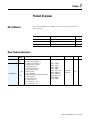
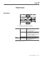
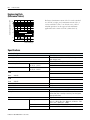
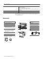
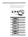
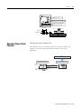
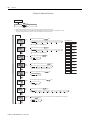
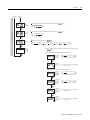
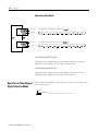
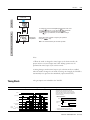
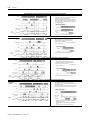
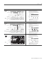
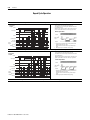
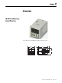
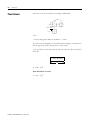
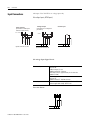
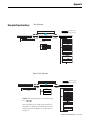
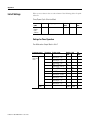
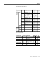
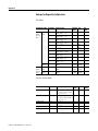
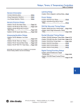
Multifunction Digital Timer
700-HX
User Manual
Important User Information
Because of the variety of uses for the products described in this publication,
those responsible for the application and use of this control equipment must
satisfy themselves that all necessary steps have been taken to assure that each
application and use meets all performance and safety requirements, including
any applicable laws, regulations, codes and standards.
The illustrations, charts, sample programs and layout examples shown in this
guide are intended solely for purposes of example. Since there are many
variables and requirements associated with any particular installation,
Allen-Bradley does not assume responsibility or liability (to include
intellectual property liability) for actual use based upon the examples shown
in this publication.
Rockwell Automation publication SGI-1.1, Safety Guidelines for the Application,
Installation and Maintenance of Solid-State Control (available from your local
Rockwell Automation sales office or Allen-Bradley distributor), describes
some important differences between solid-state equipment and
electromechanical devices that should be taken into consideration when
applying products such as those described in this publication.
Reproduction of the contents of this copyrighted publication, in whole or
part, without written permission of Rockwell Automation, is prohibited.
Throughout this manual we use notes to make you aware of safety
considerations:
ATTENTION
!
Identifies information about practices or circumstances
that can lead to personal injury or death, property damage
or economic loss
Attention statements help you to:
• identify a hazard
• avoid a hazard
• recognize the consequences
IMPORTANT
Identifies information that is critical for successful
application and understanding of the product.
European Communities (EC)
Directive Compliance
If this product has the CE mark it is approved for installation within the
European Union and EEA regions. It has been designed and tested to meet
the following directives.
EMC Directive
This product is tested to meet the Council Directive 89/336/EC
Electromagnetic Compatibility (EMC) by applying the following standards, in
whole or in part, documented in a technical construction file:
• EN 50081-2 EMC — Generic Emission Standard, Part 2 — Industrial
Environment
• EN 50082-2 EMC — Generic Immunity Standard, Part 2 — Industrial
Environment
This product is intended for use in an industrial environment.
Low Voltage Directive
This product is tested to meet Council Directive 73/23/EEC Low Voltage, by
applying the safety requirements of EN 61010-1 safety requirements for
electrical equipment for measurement, control and laboratory use--Part 1
General Safety Requirements.
This equipment is classified as open equipment and must be mounted as
instructed in an enclosure during operation to provide safety protection.
Preface
Manual Objectives
The purpose of this manual is to provide you with the additional information
necessary to apply the 700-HX Multifunction Digital Timer. Described in this
manual are methods for applying and troubleshooting this product.
Who Should Use This
Manual
This manual is intended for qualified personnel responsible for setting up and
servicing these devices. You must have previous experience with and a basic
understanding of wiring diagrams, configuration procedures, related equipment,
and safety precautions.
Counter/Timer Mode
Explanation
In this manual we refer to the Timer Output Modes with the following
designations:
A: Signal ON delay 1
A-1: Signal ON delay 2
A-2: Power ON delay 1
A-3: Power ON delay 2
B: Repeat Cycle 1
B-1: Repeat Cycle 2
D: Signal OFF delay
E: One Shot
F: Cumulative
Z: ON/OFF-duty adjustable repeat cycle
S: Stop Watch
toff: Flicker OFF start 1(Timer resets when power comes on)
ton: Flicker ON start 1 (Timer resets when power comes on)
toff-1: Flicker OFF start 2(Timer does not reset when power comes on)
ton-1: Flicker ON start 2 (Timer does not reset when power comes on)
Note: In this manual the 700-HX Multifunction Digital Timer will be referred to
as “700-HX.” For further information, please refer to the Industrial Controls
Catalog or www.ab.com/catalogs.
1
Publication 700-UM002B-EN-D June 2010
Preface
2
Publication 700-UM002B-EN-D - June 2010
Chapter
1
Product Overview
Bill of Material
Your 700-HX Multifunction Digital Timer product package includes the
following items:
Item No.
Description
Quantity
700-HX
Digital Timing Relay
1
—
6-Language Instruction Sheet
1
—
Rubber Gasket
1
Basic Product Information
Cat. No.
Input
Output Modes
Voltage
700-HX86SA17 100…240 A mode: Signal ON-Delay 1
V AC
A-1 mode: Signal ON-Delay 2
A-2 mode: Power ON-Delay 1
A-3 mode: Power On-Delay 2
B mode: Repeat Cycle 1
B-1 mode: Repeat Cycle 2
D mode: Signal OFF-delay
12…24V E mode: One Shot
F mode: Cumulative
700-HX86SU24 DC
Z mode: On/Off duty adjustable repeat cycle
24V AC
S mode:stop watch
toff: Flicker OFF start 1
ton: Flicker ON start 1
toff-1: Flicker OFF start 2
ton-1: Flicker ON start 2
1
Timing Ranges
Sockets
Output Pins
0.000…9.999 s
0.000…99.99 s
0.000…999.9 s
0.000…9999 s
0.000…99 min. 59 s
0.000…999.9 min.
0.000…9999 min.
0.000…99 h 59 min.
0.000…999.9 h
0.000…9999 h
700-HN100
700-HN125
SPDT
8
Publication 700-UM002B-EN-D - June 2010
1-2
Product Overview
Accessories
(Order Separately)
Cat. No.
700-HN100
700-HN125
199-DR1
700-HN108
700-HN130
700-HN132
700-N40
700-N41
Publication 700-UM002B-EN-D - June 2010
Description
Screw Terminal Tube Base Sockets — Panel or DIN Rail
Mounting Guarded Terminal Construction
8-pin for use with Bulletin 700-HX timing relays. Order
must be for 10 sockets or multiples of 10.
Screw Terminal Tube Base Sockets — Panel or DIN Rail
Mounting
Open Style Construction
8-pin for use with Bulletin 700-HX timing relays. Order must
be for 10 sockets or multiples of 10. No retainer clip
required.
DIN Rail Mounting Pack
Standard 35 x 7.5 mm DIN Rail, 1 meter long, 10 rails per
package. Order must be for 10 rails or multiples of 10.
Specialty Socket
8-pin backwired socket with solder terminals for use with
Bulletin 700-HX timing relays. Order must be for 10 sockets
or multiples of 10.
Frame Adapter
For flush or door mounting of all Bulletin 700-HR and -HX
timers.
Protective Cover
Helps prevent tampering of timing and mode settings.
Provides a degree of protection against water and dirt from
entering the front of the relay. For use with all Bulletin
700-HRs and -HX timing relays.
Pre-printed identification tags— contains 10 sheets of
pre-printed and blank tags. Each sheet contains 13 sets of
the markings CR…9CR, TR…9TR, M…9M, F, R, 1S, and
117 blank tags. Tags are peel-off with sticky backing for
easy placement on relays.
Pkg. Qty.
10
10
10
10
1
1
10
10
Blank identification tags— contains 10 sheets of blank
identification tags for customer specialized printing. Each
sheet contains 546 blank tags. Tags are peel-off with sticky
backing for easy placement on relays.
Chapter
2
Product Features
Block diagram
Output circuit
(Basic
insulation)
Display circuit
Input circuit
Internal control
circuit
Key switch
circuit
(See note.)
Power supply
circuit
Note: 700-HX86SA17: Basic insulation is provided
700-HX86SU24: Basic insulation is not provided
Inputs
Start signal
Reset
Outputs
Gate ➊
Control output (OUT)
Stops timing in A-2 and A-3 (power ON delay)
modes.
Starts and stops timing in S mode.
Start timing in other modes.
Resets present value. (In elapsed time mode, the
present value returns to 0; in remaining time
mode, the present value returns to the set value.)
Count inputs are not accepted and control output
turns OFF while reset input is ON.
Reset indicator is lit while reset input is ON.
Inhibits timer operation.
Outputs take place according to designated
operating mode when timer reaches
corresponding set value.
➊ Gate capability not available.
1
Publication 700-UM002B-EN-D - June 2010
2-2
Product Features
Switching operations ( 104)
Engineering Data
(Reference Values)
Reference:A maximum current of 0.15 A can be switched
at 125V DC (cosφ=1) and a maximum current of 0.1 A
can be switched if L/R is 7 ms. In both cases, a life of
100,000 operations can be expected. The minimum
applicable load is 10 mA at 5V DC (failure level: P).
1,000
500
100
30V DC L/R=7 ms
50
250V DC/30V
cos =1
10
250V AC cos =0.4
0
1
2
3
4
5
Load current (A)
Specifications
Electrical Ratings
Pilot Duty Rating
Rated supply voltage
Operating voltage range
Power consumption
Inrush Current
100…240V AC
24V AC/12…24V DC
100…240V AC
24V AC/12…24V DC
120V AC
Make
NEMA B300
100 to 240V AC, 24V AC/12 to 24V DC (50/60Hz) (permissible
ripple: 20%(p-p) max.)
85%…110% of rated supply voltage
4.3 VA
3.4 VA/1.7 W
3A
5A
30 A
15 A
240V AC
3A
1.5 A
120V AC
Break
240V AC
Hp at 120V AC
Hp at 240V AC
Mechanical
Mounting method
Display
Digits
Timer
1/4 Hp
1/3 Hp
Time ranges
Timer modes
Output modes
Publication 700-UM002B-EN-D - June 2010
Flush mounting, surface mounting, DIN mounting
7-segment, negative transmissive LCD;
Present value (red, 12 mm high characters); Set value (green,
6 mm high characters)
4 digits
0.000…9.999 s, 0.00…99.99 s, 0.0…999.9 s, 0…9999 s,
0 min. 0 s…99 min. 59 s, 0.0…999.9 min., 0 h 00 min.…99 h
59 min., 0.0 h…999.9 h, 0 h…9999 h
Elapsed time (Up), remaining time (Down), selectable
A, A-1, A-2, A-3, B, B-1, D, E, F, Z, S, toff, ton, toff-1, or ton-1
Product Features
Electrical Ratings
Inputs
Input signals
Input method
Start, reset
Power reset
Control output
External Power Supply
Key Protect
Memory backup
Accuracy of Operating Time and Setting Error ➊
2-3
Start, reset
No-voltage input via:NPN transistor or switching of contact
Minimum input signal width: 1 or 20 ms (selectable)
Minimum power-opening time: 0.5 s (Except for A-3, B-1, and
F mode)
SPDT contact output: 5 A at 250V AC, resistive load
(cosine=1)
Minimum applied load: 10 mA at 5V DC (failure level: P,
reference value)
No
Yes
EEP-ROM (overwritten 100,000 times min.), which can store
data for 10 years min.
Power-ON start: +-0.01% +-50 ms max.*
* to be rated against set value
Signal start: +- 0.005 +-30 ms max. *
* to be rated against set value
Signal start at transistor output model: +- 0.005% +-3 ms
max. ➋
If the set value is within the sensor waiting time
(250 ms max.)
➊ The values are based on the set value.
❷ The value is applied for a minimum pulse width of 1 ms.
Characteristics
Insulation resistance
Dielectric strength
Noise immunity
Static immunity
Vibration resistance
Shock resistance
Life expectancy
EMC
Malfunction
Malfunction
Mechanical
Electrical
100 MΩ min. (at 500V DC)
2000V AC, 50/60Hz for 1 min. between current-carrying terminals and
non-current-carrying metal parts
(1000V AC for 24V AC/12 to 24V DC type),
1000V AC, 50/60 Hz for 1 min. between non-continuous contacts
'+-1.5 kV (between power terminals) for 100 to 240V AC, +-480V for 24V AC/12
to 24VDC, and +-600V (between input terminals), square-wave noise by noise
simulator (pulse width: 100 ns/1 μs, 1-ns rise)
±8 kV (malfunction), ±15 kV (destruction)
10…55 Hz with 0.35 mm single amplitude each in three directions for 10 min.
98 m/s2 (approx. 10 G) each in three directions
10 million operations min.
100,000 operations min. (5 A at 250V AC, resistive load)
(EMI)
EN61812-1
Emission Enclosure:
EN55011 Group1 class A
Emission AC mains:
EN55011 Group1 class A
(EMS)
EN61812-1
Immunity ESD:
EN61000-4-2: 4 kV contact discharge (level2)
8 kV air discharge (level3)
Immunity RF-interference: EN61000-4-3: 10 V/m
Publication 700-UM002B-EN-D - June 2010
2-4
Product Features
Approved standards
UL508, CSA C22.2 No.14
Conforms to EN 61812-1
(Pollution degree 2/overvoltage category III)
Conforms to VDE0106/P 100 (Finger Protection), conforms to NEMA output
rating (N/F)
Panel surface:IP66 and NEMA Type 4X (indoors) ➊
Approx. 100 g
Enclosure ratings
Weight
➊An attached waterproof packing is necessary to ensure IP66 waterproofing between the
700-HX and installation pan.
Nomenclature
Operation Key
Display Section
1. Key Protect Indicator (orange)
2. Control Output Indicator (orange)
3. Reset Indicator (orange)
4. Present Value Display (Main display)
(Character height: 12 mm, red *)
* Characters on models with screw terminals
can be switched between red, green, and orange.
1
2
3
8
4
8. Mode Key
5
9. Reset Key
6
(Changes modes and setting items)
(Resets present value and output)
7
10. Up Keys 1 to 4
10
11. Down Keys 1 to 4
11
9
Switches
5. Time Unit Indicators
(Color is same as present value display.)
(If the time range is 0 min, 0 h, 0.0 h, or 0 h
0 min, these indicators flash to indicate
timing operation.)
6. Set Value Display (Sub-display)
(Character height: 6 mm, green)
7. Set Value 1, 2 Indicator (green)
Character Size
for Present
Value Display
12mm
Character Size
for Set Value
Display
6mm
Publication 700-UM002B-EN-D - June 2010
Front View
12. Key-protect Switch
(Default setting)
12
OFF
(Disabled)
ON
(Enabled)
Chapter
3
Functions
Settings For Advanced Functions
Power ON
Run mode
For details on operations in run mode, refer to 3-10.
Note:
See note 1.
3 s min.
See note 2.
3 s min.
1. If the mode is switched to the function setting mode during operation,
operation will continue.
2. Changes made to settings in function setting mode are enabled for the
first time when the mode is changed to run mode. Also, when settings
are changed, the timer is reset (time initialized and output turned OFF).
Press the mode button for several seconds to display the Time Range setting
screen.
Set the time range using the
timr
keys.
Time range
s
s
s
……
h
Set the timer mode using the
timm
s
keys.
Timer mode
w
Set the output mode using the
Function setting mode
outm
otim
Output mode
keys.
a
a-1
a-2
a-3
b
b-1
d
e
f
z
s
(A)
(A-1)
(A-2)
(A-3)
(b)
(b-1)
(d)
(E)
(F)
(Z)
(S)
Set each digit for the output time using the corresponding
keys.
Time Range List
Output time
∼
Display
(If the output time is set to 0.00,hold is displayed.)
Displayed for modes A, A-1, A-2, A-3, B, and B-1 only.
Input signal
width
m
(20 ms)
Set Value
0.01 s to 99.99 s
(default setting)
m
0.1 s to 999.9 s
(1 ms)
1 s to 9,999 s
Set value
upper limit
Set the key protect level using the
1
9999
(1)
(9999)
keys.
0 min 01 s to 99 min 59 s
0.1 min to 999.9 min
1 min to 9,999 min
Key protect
level
Set the key protect level using the
keys.
0 h 01 min to 99 h 59 min
kp-1
kp-2
kp-3
kp-4
kp-5
kp-6
kp-7
(KP-1)
(KP-2)
(KP-3)
(KP-4)
(KP-5)
(KP-6)
(KP-7)
0.1 h to 999.9 h
Output on
Output ON
count
alarm
countvalue
alarm
set
set value
0
~
9999
(0 x 1000 times) (9999 x 1000 times)
1 h to 9,999 h
0.001s to 9.999 s
Output on
count
Output ON
count monitor
monitor
set
value
value
1
Note: The monitor value is only displayed.
It cannot be set.
Publication 700-UM002B-EN-D - June 2010
3-2
Functions
Explanations of Functions
Time Range (timr)
Set the range to be timed in the range 0.000 s… 9,999 h. Use the operation
keys if these settings are required.
Timer Mode (timm )
Set either the elapsed time (UP) or remaining time (DOWN) mode.
Output Mode (outm)
Set the output mode. The possible settings are A, A-1, A-2, A-3, B, B-1, D, E,
F, Z and S. (For details on output mode operation, refer to “Timing Charts”
on page 3-11.)
Output Time (otim )
When using one-shot output, set the output time for one-shot output (0.01…
99.99 s). One-shot output can be used only if the selected output mode is A,
A-1, A-2, B, or B-1. If the output time is set to 0.00, hold is displayed, and the
output is held.
Input Signal Width (iflt)
Set the minimum signal input width (20 ms or 1 ms) for signal and reset
inputs. The same setting is used for all external inputs (signal and reset). If
contacts are used for the input signal, set the input signal width to 20 ms.
Processing to eliminate chattering is performed for this setting.Set the key
protect level.
Set Value Upper Limit (sl-h)
Set the upper limit for the set value when it is set in Run Mode. The limit can
be set to between 1 and 9999. This setting does not apply to the ON duty in Z
mode.
Output ON Count Alarm Set Value (on-a)
Set the alarm value for the output ON count.The limit can be set to between 0
x 1000 times and 9999 x 1000 times. (The rightmost three digits will not be
displayed.) If the total ON count of the output exceeds the alarm set value, e3
will be displayed on the Timer to indicate that the output ON count alarm
value was exceeded.
Output ON Count Monitor Value (on-c)
The monitor value is only displayed. It cannot be set. The value will be
between 0 x 1000 times and 9999 x 1000 times. (The rightmost three digits will
not be displayed.)
Publication 700-UM002B-EN-D - June 2010
Functions
3-3
Key Protect Level (kypt)
When the key-protect switch in set to ON, it is possible to prevent setting
errors by prohibiting the use of certain operation keys by specifying the key
protect level (KP-1 to KP-7). The key protect indicator is lit while the
key-protect switch is set to ON. Confirm the ON/OFF status of the
key-protect switch after the 700-HX is mounted to the panel.
(See note)
OFF
ON
Note: Factory-set to OFF
Key protect indicator
Level
KP-1
(default
setting)
KP-2
KP-3
KP-4
KP-5
KP-6
KP-7
Meaning
Prohibits changing the mode to timer/repeat
cycle selection mode or function setting
mode. The 700-HX can only be used in run
mode.
Prohibits changing the mode to timer/repeat
cycle selection mode or function setting
mode. The 700-HX can only be used in run
mode. Also prohibits use of the reset key.
Prohibits changing the mode to timer/repeat
cycle selection mode or function setting
mode. The 700-HX can only be used in run
mode. Also prohibits use of the up and down
keys.
Prohibits changing the mode to timer/repeat
cycle selection mode or function setting
mode. The 700-HX can only be used in run
mode. Also prohibits use of the reset, up and
down keys.
Prohibits changing the mode to timer/repeat
cycle selection mode or function setting
mode. The 700-HX can only be used in run
mode. Also prohibits use of any operation
keys.
Prohibits changing the mode to timer/repeat
cycle selection mode or function setting
mode. The 700-HX can only be used in run
mode. Also prohibits use of the mode key.
Prohibits changing the mode to timer/repeat
cycle selection mode or function setting
mode. The 700-HX can only be used in run
mode. Also prohibits use of mode and reset
keys.
Publication 700-UM002B-EN-D - June 2010
3-4
Functions
Operation in Run Mode
When Output Mode Is Not Z
Present value
Set each digit for the set value using the corresponding
keys.
Set value
When Output Mode Z Is Selected
Present value
Set each digit for the ON duty ratio using the corresponding
(The
keys for the 4th digit cannot be used.)
keys.
ON duty ratio
Present value
Set each digit for the cycle time using the corresponding
keys.
Cycle time
Present Value and Set Value
These items are displayed when the power is turned ON. The present value is
displayed in the main display and the set value is displayed in the sub-display.
The values displayed will be determined by the settings made for the time
range and the timer mode in function setting mode.
Present Value and ON Duty Ratio (Output Mode = Z)
The present value is displayed in the main display and the ON duty ratio is
displayed in the sub-display. “SET1” lights at the same time.
Set the ON duty ratio used in ON/OFF-duty adjustable Repeat Cycle (Z) as a
percentage.
If a cycle time is set, cyclic control can be performed in ON/OFF-duty
adjustable Repeat Cycle simply by changing the ON duty ratio.
Present Value and Cycle Time (Output Mode = Z)
The present value is displayed in the main display and the cycle time is
displayed in the sub-display. “SET2” lights at the same time.
Set the cycle time used in ON/OFF-duty adjustable Repeat Cycle (Z).
Publication 700-UM002B-EN-D - June 2010
Functions
3-5
Elapsed cycle time
ON duty set as a percentage
Up/down keys used for analog
adjustment of the ON duty
Cycle time
Close
Open
ON duty (%)
Output control
Opening/closing valve
ON duty
Operation (Repeat Cycle
Function)
Fully closed↔Fully open
0%↔100%
Switching from Timer to Repeat Cycle
The 700-HX is factory-set for timer operation. To switch to repeat cycle
operation, use the procedure given below. For details, refer to page
Appendix-2.
Power ON
Timer/repeat cycle selection mode
Function
selection
Run mode
1
m
Hold down for
1 s min.
Switch from timer operation to repeat cycle
operation using the
keys.
Publication 700-UM002B-EN-D - June 2010
3-6
Functions
Settings for Advanced Functions
.
Power ON
3 s min.
Run mode
*1
Function setting mode
3 s min.
*2
*1. If the mode is switched to the function setting mode during operation, operation will continue.
*2. Changes made to settings in function setting mode are enabled for the first time when the mode is changed to run mode.
Also, when settings are changed, the timer is reset (time initialized and output turned OFF).
OFF time
range
Set the OFF time range using the
keys.
Time Range List
s
s
……
s
h
s
Display
ON time
range
Set the ON time range using the
keys.
s
s
0.1 s to 999.9 s
……
s
h
s
1 s to 9999 s
For details, refer to Time Range List.
Set the timer mode using the
0 min 01 s to
99 min 59 s
keys.
0.1 min to
999.9 min
Timer mode
up
(UP)
down
1 min to
9999 min
(DOWN)
Function setting mode
Set the repeat cycle mode using the
0 h 01 min to
99 h 59 min
keys.
ON/OFF
start mode
0.1 h to 999.9 h
toff
ton
tof1
ton1
Flicker
Flicker
Flicker
( OFFFlicker
start 1) ( On Start 1 ) ( OFF start 2 ) ( On Start 2 )
Input signal
width
Set the input signal width using the
20ms
(20 ms)
NPN/PNP
input
0.001 s to
9.999 s
keys.
1ms
(1 ms)
Set the NPN/PNP input mode using the
npn
1 h to 9999 h
keys.
pnp
(NPN input) (PNP input)
Set the display color using the
keys.
Display
color
Instantaneous/
time-limit
red
grn
org
r-g
g-r
r-o
o-r
(Red)
(Green)
(Orange)
(Red-green)
(Green-red)
(Red-orange)
(Orange-red)
1c1c
Publication 700-UM002B-EN-D - June 2010
g-o
o-g
(Green-orange) (Orange-green)
Set the function (instantaneous or time-limit operation) for the instantaneous output (output 1)
using the
Keys.
2c
(Instantaneous) (Time-limit)
To next page From next page
Set Value
0.01 s to 99.99 s
(default setting)
For details, refer to Time Range List.
Functions
From previous
page
3-7
To previous
page
Function setting mode
Set value
upper limit 1
Set value
upper limit 2
Set the digits for the set value limit using the corresponding
1
9999
(1)
(9999)
Set the digits for the set value limit using the corresponding
1
9999
(1)
(9999)
Set the key protect level using the
keys.
keys.
keys.
Key protect
level
kp-1
kp-2
kp-3
kp-4
kp-5
kp-6
kp-7
(KP-1)
(KP-2)
(KP-3)
(KP-4)
(KP-5)
(KP-6)
(KP-7)
*1
Output ON
count alarm
set value/
monitor value
*1. Set the digits for the output ON alarm set value using the corresponding
keys.
• Models without Instantaneous Contact Outputs
Output ON
count alarm
set value
Output ON
count monitor
value
0
~
9999
(0 x 1000 times) (9999 x 1000 times)
Note: The monitor value is only displayed.
It cannot be set.
• Models with Instantaneous Contact Outputs
Instantaneous
output 1
(OUT1) ON
count alarm
set value
Instantaneous
output 2
(OUT2) ON
count alarm
set value
0
~
9999
(0 x 1000 times) (9999 x 1000 times)
0
~
9999
(0 x 1000 times) (9999 x 1000 times)
Instantaneous
output 1
(OUT1) ON
count monitor
value
Note: The monitor value is only displayed.
It cannot be set.
Instantaneous
output 2
(OUT2) ON
count monitor
value
Note: The monitor value is only displayed.
It cannot be set.
Publication 700-UM002B-EN-D - June 2010
3-8
Functions
Explanation of Functions (Repeat Cycle Function)
OFF Time Range (oftr)
Set the time range for the OFF time in the range 0.000 s… 9,999 h. Use the
operation keys if another type of setting is required.
ON Time Range (ontr)
Set the time range for the ON time in the range 0.000 s …9,999 h. Use the
operation keys if another type of setting is required.
Timer Mode (timm)
Set either UP (incremental) or DOWN (decremental) timer mode. In UP
mode, the elapsed time is displayed, and in DOWN mode, the remaining time
is displayed.
ON/OFF Start Mode (totm)
Set the output mode. Set either Repeat Cycle OFF start or Repeat Cycle ON
start. (For details on output mode operation, refer to 3-11.)
Input Signal Width (iflt) (Setting possible using DIP switch.)
Set the minimum signal input width (20 ms or 1 ms) for signal, reset, and gate
inputs. The same setting is used for all external inputs (signal and rese ). If
contacts are used for the input signal, set the input signal width to 20 ms.
Processing to eliminate chattering is performed for this setting.
Key Protect Level (kypt)
Set the key protect level.
When the key-protect switch in set to ON, it is possible to prevent setting
errors by prohibiting the use of certain operation keys by specifying the key
protect level (KP-1 to KP-7). The key protect indicator is lit while the
key-protect switch is set to ON. Confirm the ON/OFF status of the
key-protect switch after the 700-HX is mounted to the panel.
Publication 700-UM002B-EN-D - June 2010
Functions
(See note)
OFF
3-9
ON
Note: Factory-set to OFF
Key protect indicator
Level
KP-1
(default
setting)
KP-2
KP-3
KP-4
KP-5
KP-6
KP-7
Meaning
Prohibits changing the mode to timer/repeat
cycle selection mode or function setting
mode. The 700-HX can only be used in run
mode.
Prohibits changing the mode to timer/repeat
cycle selection mode or function setting
mode. The 700-HX can only be used in run
mode. Also prohibits use of the reset key.
Prohibits changing the mode to timer/repeat
cycle selection mode or function setting
mode. The 700-HX can only be used in run
mode. Also prohibits use of the up and down
keys.
Prohibits changing the mode to timer/repeat
cycle selection mode or function setting
mode. The 700-HX can only be used in run
mode. Also prohibits use of the reset, up and
down keys.
Prohibits changing the mode to timer/repeat
cycle selection mode or function setting
mode. The 700-HX can only be used in run
mode. Also prohibits use of any operation
keys.
Prohibits changing the mode to timer/repeat
cycle selection mode or function setting
mode. The 700-HX can only be used in run
mode. Also prohibits use of the mode key.
Prohibits changing the mode to timer/repeat
cycle selection mode or function setting
mode. The 700-HX can only be used in run
mode. Also prohibits use of mode and reset
keys.
Publication 700-UM002B-EN-D - June 2010
3-10
Functions
Operation in Run Mode
Present value
Set the digits for the OFF set time using the corresponding
keys.
OFF set time
Present value
Set the digits for the ON set time using the corresponding
keys.
ON set time
Present Value and OFF Set Time
The present value is displayed in the main display and the OFF set time is
displayed in the sub-display. “SET1” lights at the same time.
Present Value and ON Set Time
The present value is displayed in the main display and the ON set time is
displayed in the sub-display. “SET2” lights at the same time.
Operation in Timer/Repeat
Cycle Selection Mode
Select whether the 700-HX is used as a timer or a repeat cycle in timer/repeat
cycle selection mode.
One-shot
Sustained output
One-shot outputs can be to set to 0.1 s, 0.5 s, 1s, 5 s, 10 s, 20 s.
Publication 700-UM002B-EN-D - June 2010
Functions
3-11
Run Mode
Power ON
+
To change the mode to timer/ repeat cycle selection mode, hold
1 key for 1 s min. with the MODE key held down.
down the
The MODE key must be pressed before the
1 key.
If the
1 key is pressed first, the mode will not change.
1
Timer/ Repeat cycle Selection Mode
1 s min.
Select either timer operation or repeat cycle operation.
using the
keys.
Timer/Repeat
m
cycle operation
MODE
Note: The 700-HX is factory-set for timer operation.
Note:
1. When the mode is changed to timer/repeat cycle selection mode, the
present value is reset and output turns OFF. Timing operation is not
performed in timer/repeat Cycle selection mode.
2. Setting changes made in timer/repeat cycle selection mode are enabled
when the mode is changed to run mode. If settings are changed, the 700-HX is
automatically reset (present value initialized, output turned OFF).
Timing Charts
The gate input is not included in the 700-HX.
Output mode A Mode: Signal ON-Delay (Timer resets when power comes ON.)
Timing starts when the start signal goes ON.
While the start signal is ON, the timer starts when
power comes ON or when the reset input goes OFF.
The control output is controlled using a sustained or
one-shot rime period.
Power
Start signal
Basic Operation
Gate
Power
Reset
t
t
t
**
Start signal
input
Timing
Control output
Set value
Timing
diagram
UP
Output
0
Set value
DOWN
0
* Output is instantaneous when setting is 0.
** Start signal input is enabled during timing.
Publication 700-UM002B-EN-D - June 2010
3-12
Functions
Output Mode A-1: Signal ON-Delay 2 (Timer resets when power comes ON.)
Power
Timing starts when the start signal goes ON, and is
reset when the start signal goes OFF.
While the start signal is ON, the timer starts when the
power comes ON or when the reset input goes OFF.
The control output is controlled using a sustained or
one-shot time period.
Start signal
Gate
Basic Operation
Reset
Power
Control output
Set value
UP
Timing
diagram
Start signal
input
0
Set value
DOWN
0
Timing
Output
*Output is instantaneous when setting is 0.
Output mode A-2: Power ON Delay 1 (Timer resets when power comes ON)
Power
Timing starts when the reset input goes OFF.
The start signal disables the timing function (i.e., same
function as the gate input).
The control output is controlled using a sustained or
one-shot time period.
.
Start signal
Gate
Basic Operation
Reset
Power
Control output
Set value
UP
Timing
0
diagram
Set value
DOWN
0
Timing
Output
*Output is instantaneous when setting is 0.
Output mode A-3 Power ON Delay 2 (Timer does not reset when power comes ON)
Power
Timing starts when the reset input goes OFF.
The start signal disables the timing function (i.e.,
same function as the gate input).
The control output is controlled using a sustained or
one-shot time period.
.
Start signal
Gate
Basic Operation
Reset
t
Power
Control output
Output
Set value
Timing
diagram
UP
0
Timing
Sustained
*Output is instantaneous when setting is 0.
Set value
DOWN
0
Output mode B: Repeat Cycle 1 (Timer resets when power comes ON.)
Sustained
Output
Power
Start signal
Gate
Reset
Control output
Set value
Timing
diagram
UP
Timing starts when the start signal goes ON.
The status of the control output is reversed when time
is up (OFF at start).
While the start signal is ON, the timer starts when the
power comes ON or when the reset input goes OFF.
Basic Operation
Power
**
Start signal
input
Timing
Timing
Timing Timing
0
Set value
DOWN
0
Publication 700-UM002B-EN-D - June 2010
Output
* Normal output operation will not be possible if the
set time is too short.
Set the value to at least 100 ms (contact output
type).
** Start signal input is disabled during timing.
Functions
3-13
Output mode B: Repeat Cycle 1 (Timer resets when power comes ON.)
One-shot
Output
Timing starts when the start signal goes ON.
The control output is turned ON when time is up.
While the start signal is ON, the timer starts when the
power comes ON or when the reset input goes OFF.
Power
Start signal
Basic Operation
Gate
Power
Reset
Timing
diagram
**
Start signal
input
Control output
Set value
UP
0
Timing
Timing Timing
Timing
Output
Set value
DOWN
0
* Normal output operation will not be possible if the
set time is too short.
Set the value to at least 100 ms (contact output
type).
** Start signal input is disabled during timing.
Output Mode B-1: Repeat Cycle 2 (Timer does not reset when power comes ON)
Sustained
Output
Timing starts when the start signal goes ON.
The status of the control output is reversed when time
is up (OFF at start).
While the start signal is ON, the timer starts when the
power comes ON or when the reset input goes OFF.
Power
Start signal
Basic Operation
Gate
Power
Reset
**
Start signal
input
Control output
Timing
diagram
Set value
UP
0
Sustained Timing
Output
Set value
DOWN
0
One-shot
Output
Timing
* Normal output operation will not be possible if the
set time is too short.
Set the value to at least 100 ms (contact output
type).
** Start signal input is disabled during timing.
Timing starts when the start signal goes ON.
The control output comes ON when time is up..
While the start signal is ON, the timer starts when
power comes ON or when the reset input goes OFF.
Power
Start signal
Basic Operation
Gate
Power
Reset
t
Control output
Set value
Timing
diagram
UP
t
t
t
**
Start signal
input
Timing
Sustained Timing
Output
0
Set value
DOWN
t
0
* Normal output operation will not be possible if the
set time is too short.
Set the value to at least 100 ms (contact output
type).
** Start signal input is disabled during timing.
Publication 700-UM002B-EN-D - June 2010
3-14
Functions
Output mode D: Signal OFF-delay (Timer resets when power comes ON.)
The control output is ON when the start signal is
ON (except when the power is OFF or the reset is
ON).
The timer is reset when the time is up.
Power
Start signal
Basic Operation
Gate
Power
Reset
**
Start signal
input
Control output
Set value
UP
Timing
diagram
0
Set value
DOWN
0
Timing
Output
* Output functions only during start signal input when
setting is 0.
** Start signal input is enabled during timing.
Output mode E: One Shot (Timer resets when power comes ON.)
Power
Timing starts when the start signal comes ON.
The control output is reset when time is up.
While the start signal is ON, the timer starts when
power comes ON or when the reset input goes OFF.
Start signal
Gate
Basic Operation
Reset
Power
Control output
**
Start signal
input
Set value
Timing
diagram
Timing
UP
0
Set value
DOWN
0
Output
* Output is disabled when the setting is 0.
** Start signal input is enabled during timing.
Output Mode F: Cumulative (Timer does not reset when power comes ON)
Start signal enables timing (timing is stopped when the
start signal is OFF or when the power is OFF).
A sustained control output is used.
Power
Start signal
Basic Operation
Gate
Power
Reset
Start signal
input
Control output
Set value
Timing
diagram
Output
UP
0
Set value
DOWN
0
Timing
Timing
Sustained
*Output is instantaneous when setting is 0.
Z Mode
Output quantity can be adjusted by changing the cycle time set in the
adjustment level to 1 and by changing the ON duty (%) set value. The set value
shows the ON duty (%) and can be set to a value between 0 and 100 (%).
When the cycle time is 0, the output will always be OFF. When the cycle time
is not 0 and when ON duty has been set to 0 (%), the output will always be
OFF. When ON duty has been set to 100 (%), the output will always be ON.
Publication 700-UM002B-EN-D - June 2010
Functions
3-15
Z mode: ON/OFF-duty Adjustable Repeat Cycle
Power
Start signal
Gate
Timing starts when the start signal goes ON.
The status of the control output is reversed
when time is up (ON at start).
While the start signal is ON, the timer starts when
power comes ON or when the reset input goes OFF.
Basic Operation
Power
Reset
Control output
**
Start signal
input
Cycle time
Timing
diagram
Timing
ON duty (%)
0
UP
ON duty setting
(%) ON time
DOWN
0
Timing
(cycle time)
Timing
(cycle time)
Cycle time
ON duty setting
(%) ON time
Timing
ON duty (%)
Output
* Normal output operation will not be possible if the
set time is too short.
Set the value to at least 100 ms (contact output
type).
** Start signal input is enabled during timing.
S mode: Stop Watch (Timer Resets when Power Comes On)
Power
Start signal
Gate/Reset
The signal starts and stops timing.
The display is held and timing is continued if the reset
or gate input is received during timing operation.
The timer resets if the reset or gate input is received
when the timing operation is stopped.
Basic Operation
9999
Timing diagram
Set time
Power
UP
0
Set time
Start signal
input
Timing
Gate/Reset
DOWN
0
Output
Display
(for elapsed
time)
*
* RST flashes
Note: Output is instantaneous when setting is 0.
Publication 700-UM002B-EN-D - June 2010
3-16
Functions
Repeat Cycle Operation
Output mode TOFF: Flicker OFF start 1 (Timer resets when power comes ON)
Timing starts when the start signal goes ON.
The status of the control output is reversed when time
is up (OFF at start).
While the start signal is ON, the timer starts when the
power comes ON or when the reset input goes OFF.
Sustained
Output
Power
Start signal
Basic Operation
Gate
Power
Reset
**
Start signal
input
Control output
OFF time
UP
Timing
ON
Timing
OFF
Timing
ON
Output
ON time
Timing
diagram
Timing
OFF
* Normal output operation will not be possible if the
ON/OFF set time is too short.
Set the value to at least 100 ms (contact output
type).
** Start signal input is disabled during timing.
0
OFF time
DOWN
ON time
0
Output mode TON: Flicker ON start 1 (Timer resets when power comes ON)
Timing starts when the start signal goes ON.
The status of the control output is reversed when time
is up (ON at start).
While the start signal is ON, the timer starts when the
power comes ON or when the reset input goes OFF.
Sustained
Output
Power
Start signal
Basic Operation
Gate
Power
Reset
**
Start signal
input
Control output
OFF time
UP
Timing
ON
Timing
OFF
Timing Timing
ON
OFF
Output
ON time
* Normal output operation will not be possible if the
ON/OFF set time is too short.
Set the value to at least 100 ms (contact output
type).
** Start signal input is disabled during timing.
Timing
0
diagram
OFF time
DOWN
ON time
0
Output mode TOFF-1: Flicker OFF start 2 (Timer does not reset when power comes ON)
Publication 700-UM002B-EN-D - June 2010
Functions
3-17
Timing starts when the start signal goes ON.
The status of the control output is reversed when time is
up (OFF at start).
While the start signal is ON, the timer starts when the
power comes ON or when the reset input goes OFF.
Power
Start signal
Basic Operation
Gate
Power
Reset
*
Start signal
input
OFF time
UP
ON time
Timing
OFF
Timing
ON
Timing
OFF
a
b
Output
(a + b = ON time)
* Start signal input is disabled during timing.
0
Note: Normal output operation will not be possible if
the set time is too short.
Set the value to at least 100 ms (contact output
type).
OFF time
DOWN
ON time
0
Output mode TON-1: Flicker ON start 2 (Timer does not reset when power comes ON)
Power
Start signal
Timing starts when the start signal goes ON.
The status of the control output is reversed when time is
up (ON at start).
While the start signal is ON, the timer starts when the
power comes ON or when the reset input goes OFF.
Basic Operation
Gate
Power
Reset
Control output
Timing diagram
Timing diagram
Control output
OFF time
UP
ON time
0
OFF time
DOWN
ON time
0
*
Start signal
input
Timing
ON
Timing
OFF
Timing
ON
a
b
Output
(a + b = OFF time)
* Start signal input is disabled during timing.
Note: Normal output operation will not be possible if
the set time is too short.
Set the value to at least 100 ms (contact output
type).
Publication 700-UM002B-EN-D - June 2010
3-18
Functions
Publication 700-UM002B-EN-D - June 2010
Chapter
4
Dimensions
700-HX Flush Mounting/
Socket Mounting
Note: All units are in millimeters unless otherwise noted.
48×48
7.5
63.7
14.3
44.8×44.8
1
Publication 700-UM002B-EN-D - June 2010
4-2
Dimensions
Panel Cutouts
Panel cutouts are as shown below (according to DIN43700).
60 min.
45 +0.6
−0
45 +0.6
−0
60 min. 15 min.
Note:
1. The mounting panel thickness should be 1…5 mm.
2. To allow easier operability, it is recommended that adapters are mounted so
that the gap between sides with hooks is at least 15 mm.
3. It is possible to mount timers side by side, but only in the direction without
the hooks.
n side by side mounting
A
+1
A = (48n - 2.5)0
With 700-HN132 attached:
A = (51n - 5.5)+1
0
Publication 700-UM002B-EN-D - June 2010
Chapter
5
Installation
Terminal Arrangement
700-HX
Internal circuit
Signal
Reset
4
5
3
6
7
2
1
8
0V
ϑҥϒ
(–) ϑҤϒ
(+)
Note: Do not connect unused terminals as relay terminals.
Input Circuits
Start and reset Input
+14 V
1k
IN
1
Internal circuit
Publication 700-UM002B-EN-D - June 2010
5-2
Installation
Input Connections
The input of the 700-HX is no-voltage input only.
No-voltage Inputs (NPN Inputs)
Open Collector
(Connection to NPN open
collector output sensor)
PC or sensor
Voltage Output
(Connection to a voltage out
put sensor)
Contact input
700-HX
Operate with transistor ON
➀ ➂
➃
700-HX
➀ ➂
Signal input
Input
0V
Reset input
Signal input
Input
0V
Reset input
Signal input
Input
0V
Reset input
Sensor
➃
Operate with relay ON
Operate with transistor ON
No-voltage Input Signal Levels
No-contact input
Contact input
Short-circuit level
Transistor ON
Residual voltage: 2 V max.
Impedance when ON: 1 KΩ max.
(the leakage current is approximately 12 mA when the
impedance is 0Ω)
Open level
Transistor OFF
Impedance when OFF: 100 KΩ minimum.
Use contact which can adequately switch 5 mA at 10V
Maximum applicable voltage: 30V DC max.
700-HX
Publication 700-UM002B-EN-D - June 2010
➀ ➂
Signal input
Input
0V
Reset input
Two-wire Sensor
➃
Installation
5-3
Applicable Two-wire Sensor
Leakage current:
1.5 mA max.
Switching capacity: 5 mA minimum
Residual voltage:
3V DC max.
Operating voltage:
10V DC
Publication 700-UM002B-EN-D - June 2010
5-4
Installation
Publication 700-UM002B-EN-D - June 2010
Chapter
7
Precautions
ATTENTION
!
ATTENTION
!
ATTENTION
!
ATTENTION
!
1
Do not use the product in locations subject to flammable
or explosive gases. Doing so may result in explosion.
The service life of the output relays depends on the
switching capacity and switching conditions. Consider the
actual application conditions and use the product within
the rated load and electrical service life. Using the product
beyond its service life may result in contact deposition or
burning.
Do not disassemble, repair, or modify the product. Doing
so may result in electric shock, fire, or malfunction.
Do not allow metal objects or conductive wires to enter the
product. Doing so may result in electric shock, fire, or
malfunction.
Publication 700-UM002B-EN-D - June 2010
7-2
Precautions
Power Supplies
Make sure that the voltage is applied within the specified range, otherwise the
internal elements of the Timer may be damaged.
When turning the power ON and OFF, input signal reception is possible,
unstable, or impossible as shown in the diagram below.
Power ON
supply OFF
200 ms 0 to 50 ms
Input
Impossible
5 ms
Possible
0 to 500 ms
Unstable Impossible
Unstable
Turn the power ON and OFF using a relay with a rated capacity of 10 A
minimum to prevent contact deterioration due to inrush current caused by
turning the power ON and OFF.
Apply the power supply voltage through a relay or switch in such a way that
the voltage reaches a fixed value immediately, otherwise they may not be reset
or a timer error may result.
Be sure that the capacity of the power supply is large enough, otherwise the
Timer may not start due to inrush current (approx. 5 A) that may flow for an
instant when the Timer is turned on.
Make sure that the fluctuation of the supply voltage is within the permissible
range.
Timer Control with Power
Start
To allow for the startup time of peripheral devices (sensors, etc.), the 700-HX
starts timing operation between 200 ms…260 ms after power is turned ON.
For this reason, in operations where timing starts from power ON, the time
display will actually start from 250 ms. If the set value is 249 ms or less, the
time until output turns ON will be a fixed value between 200…250. (Normal
operation is possible for set value of 250 ms or more.) In applications in which
a set value of 249 ms or less is required, use start timing with signal input.
When the 700-HX is used with power start in F mode (i.e., accumulative
operation with output on hold), there will be a timer error (approximately
100 ms each time the 700-HX is turned ON) due to the characteristics of the
internal circuitry. Use the 700-HX with signal start if timer accuracy is
required.
Publication 700-UM002B-EN-D - June 2010
Precautions
Self-diagnostic Function
7-3
The following displays will appear if an error occurs.
Confirm the error type using the display, and take the appropriate
countermeasures.
Main display Sub- display
No
e1
display
No
display
e2
e2
sum
No Change
e3 ➋
Error
CPU
Memory (RAM)
Memory (EEP)
➊
Output ON count
alarm set value
exceeded
Correction
Either press the reset key or reset
the power supply.
Reset the power supply. If normal
operation is still not restored,
replacement or repair is necesary. If
normal operation is restored, the
cause may have been noise.
Reset to the factory settings using
the reset key.
Reset key
➊ This includes times when the life of the EEPROM has expired.
➋ The normal display and e3 will appear alternately. When the Reset Key is pressed, e3 will
no longer be displayed even if the alarm set value is exceeded. (Monitoring is possible,
however, because the Timer will continue without clearing the output ON count.)
Changing the Set Values
When changing the set value during a timing operation, the output will turn
ON if the set value is changed as follows because of the use of a constant
read-in system:
Elapsed time mode: Present value ≥ set value
Remaining time mode: Elapsed time ≥ set value (The present value is set to 0.)
NOTE: When in the remaining time mode, the amount the set value is
changed is added to or subtracted from the present value.
Operation with a Set Value
of 0
Operation with a set value of 0 will vary with the output mode. Refer to 3-11.
Power Failure Backup
All data is stored in the EEPROM when there is power failure. The EEPROM
can be overwritten more than 100,000 times.
Publication 700-UM002B-EN-D - June 2010
7-4
Precautions
Operating mode
A-3, b-1, F, toff-1/
ton-1 mode
Other mode
Overwriting timing
When power is turned OFF.
When settings are changed.
Wiring
Wiring input lines in the same conduit as power lines or other high-voltage
lines may result in malfunction due to noise. Wire the input lines separately,
away from lines carrying high-voltages. In addition, make the input wiring as
short as possible and use shield lines or metal wiring conduits.
Mounting
Dense mounting may result in a reduction in the service life of internal parts.
Tighten the two mounting screws on the Adaptor. Tighten them alternately, a
little at a time, so as to keep them at an equal tightness.
The 700-HX panel surface is water-resistant (conforming to NEMA 4 and
IP66). In order to prevent the internal circuit from water penetration through
the space between the timer and operating panel, attach a waterproof gasket
between the timer and installation panel and secure the waterproof gasket with
the 700-HN130 flush-mounting adapter.
0.5 to 1 mm
It is recommended that the space between
the screw head and the adapter should be
0.5 to 1 mm.
Operating Environment
•
•
•
•
•
Publication 700-UM002B-EN-D - June 2010
Use the product within the ratings specified for submerging in
water, and exposure to oil.
Do not use the product in locations subject to vibrations or
shocks. Using the product in such locations over a long period
may result in damage due to stress.
Do not use the product in locations subject to dust, corrosive
gases, or direct sunlight.
Separate the input signal devices, input signal cables, and the
product from the source of noise or high-tension cables producing
noise.
Separate the product from the source of static electricity when
using the product in an environment in which a large amount of
static electricity is produced (e.g., forming compounds, powders,
or fluid materials being transported by pipe).
Precautions
•
•
•
•
•
7-5
Organic solvents (such as paint thinner), as well as very acidic or
basic solutions might damage the outer casing of the timer.
Use the product within the ratings specified for temperature
and humidity.
Do not use the product in locations where condensation may
occur due to high humidity or where temperature changes
are severe.
Store at the specified temperature. If the 700-HX has been stored
at a temperature of less than –10°C, allow the 700-HX to stand at
room temperature for at least 3 hours before use.
Leaving the 700-HX with outputs ON at a high temperature for a
long time may hasten the degradation of internal parts (such as
electrolytic capacitors). Therefore, use the product in combination with relays and avoid leaving the product as long as more
than 1 month with the output turned ON.
X2/b
T
T/a
X1/a
X1
X1/a
X2
X
Auxiliary
relay
Auxiliary
relay
(e.g., MY Relay)
(e.g. 700-HC Relay)
Insulation
There is no insulation between power supply and input terminals.
Basic insulation between power supply and output terminals.
Input and output terminals are connected to devices without exposed charged
parts.
Input and output terminals are connected to devices with basic insulation that
is suitable for the maximum operating voltage.
Publication 700-UM002B-EN-D - June 2010
7-6
Precautions
Publication 700-UM002B-EN-D - June 2010
Appendix
Using the Operation Keys
Timer Operation
Operation stopped
Can be in operation
Power ON
Timer/Repeat Cycle selection mode
+
1
+
1
1 s min.
Run mode
3 s min.
Timer (Except for Z mode) 3 s min.
Timer/Repeat Cycle selection 1 s min.
PV/SV
Function setting mode
Time range
Timer mode
Timer (Z mode)
Output mode
PV/ON duty ratio
Output time
PV/cycle time
Input signal width
Set value upper limit
Key protect level
Output on alarm set
value
Output on alarm monitor
value
Repeat Cycle Operation
Operation stopped
Can be in operation
Power ON
Timer/Repeat Cycle selection mode
+
+
Timer/Repeat Cycle selection
1
1 s min.
Run mode
3 s min.
Function setting mode
1
1 s min.
3 s min.
PV/OFF
set time
PV/SV
Time range
Timer mode
PV/ON set time
Timer (Z mode)
PV/ON duty ratio
Output mode
Output time
Input signal width
NOTE: All setting changes are performed
PV/cycle timeusing
keys
.
Set value upper limit
Key protect level
The flowcharts above outline the procedure for
all models. For details on specific models, refer to
Timer operation and Repeat Cycle operation in
Chapter 3.
1
Output on alarm set
value
Output on alarm monitor
value
Publication 700-UM002B-EN-D - June 2010
Appendix-2
List of Settings
Fill in your set values in the set value column of the following tables for quick
reference.
Timer/Repeat Cycle Selection Mode
Parameter Parameter Setting range
name
func
tim/twin
Timer/
Repeat
Cycle
selection
Dafault
value
Unit
tim
---
Set
value
Settings for Timer Operation
Run Mode when Output Mode is Not Z
Parameter name
Present Set value
value, set
value
Present
value
Publication 700-UM002B-EN-D - June 2010
Parameter Setting range
0.00 … 99.99
(Time range: --,--s)
0.0 … 999.9
(Time range: ---,-s)
0 … 9999
(Time range: ----s)
0:00 … 99:59
(Time range: --min--s)
0.0 … 999.9
(Time range: ---,-min)
0 … 9999
(Time range: ----min)
0:00 … 99:59
(Time range: --h--min)
0.0 … 999.9
(Time range: ---,-h)
0 … 9999
(Time range: ----h)
0.000 … 9.999
(Time range: -,---s)
Same as set value
Default Unit
value
0.00
s
0.0
s
0
s
0:00
min; s
0.0
min
0
min
0:00
h; min
0.0
h
0
h
0.000
s
Same
as left
Same
as left
Set
value
Appendix-3
Run Mode when Output Mode = Z
Parameter
name
Present Cycle
value, time
cycle
time
Parameter Setting range
Dafault Unit
value
0.00
s
0.00 …99.99
(Time range: --,--s)
0.0 … 999.9
0.0
(Time range: ---,-s)
0 … 9999 (Time range: ----s) 0
Present
value
Present ON
value, duty
ratio
ON
duty
Present
ratio
value
Set
value
s
0:00 … 99:59
(Time range: --min--s)
0.0 … 999.9
(Time range: ---,-min)
0 … 9999
(Time range: ----min)
0:00 … 99:59
(Time range: --h--min)
0.0 … 999.9
(Time range: ---,-h)
0 … 9999 (Time range:
----h)
0.000 … 9.999
(Time range: -,---s)
0:00
s
min; s
0.0
min
0
min
0:00
h; min
0.0
h
0
h
0.000
s
Same as cycle time above
Same
as left
0…100
0
Same
as left
%
Same as cycle time above
Same
as left
Same
as left
Function Setting Mode
Parameter name
Parameter Setting range
Time range
timr
Timer mode
Output mode
timm
Output time
Input signal width
Key protect level
Dafault Unit
value
--,--s/---,-s/----s/--min--s/
---,-min/----min/--h--min/
---,-h/----h/-,---s
up down
up
---
a
---
otim
a a-1 a-2 a-3 b b-1
d e f s
hold 0.01 to 99.99
hold
s
iflt
20ms 1ms
20ms
---
kypt
kp-1 kp-2 kp-3
kp-4 kp-5 kp-6
kp-7
kp-1
---
outm
Set
value
---
Publication 700-UM002B-EN-D - June 2010
Appendix-4
Settings for Repeat Cycle Operation
Run Mode
Parameter name Parameter Setting range
0.00 …99.99
(Time range: --,--s)
0.0 … 999.9
(Time range: ---,-s)
0 … 9999
(Time range: ----s)
0:00 … 99:59
(Time range: --min--s)
0.0 … 999.9
(Time range: ---,-min)
0 … 9999
(Time range: ----min)
0:00 … 99:59
(Time range: --h--min)
0.0 … 999.9
(Time range: ---,-h)
0 … 9999
(Time range: ----h)
0.000 … 9.999 (Time
range: -,---s)
Present OFF set
time
value,
OFF set
time
Present
value
Present ON set
time
value,
ON set Present
time
value
Same as OFF set time
above
Same as OFF set time
above
Same as OFF set time
above
Dafault Unit
value
0.00
s
0.0
s
0
s
0:00
min; s
0.0
min
0
min
0:00
h; min
0.0
h
0
h
0.000
s
Same
as left
Same
as left
Same
as left
Same
as left
Same
as left
Same
as left
Set
value
Function Setting Mode
Publication 700-UM002B-EN-D - June 2010
Parameter name
Parameter Setting range
Dafault Unit
value
OFF time range
oftr
--,--s
---
ON time range
ontr
--,--s
---
Timer mode
ON/OFF start mode
timm
Input signal width
Key protect level
iflt
totm
kypt
--,--s/---,-s/----s/--min--s/
---,-min/----min/--h--min/
---,-h/----h/-,---s
--,--s/---,-s/----s/--min--s/
---,-min/----min/--h--min/
---,-h/----h/-,---s
up/down
toff/ton,/toff-1/
ton,-1
20ms/1ms
up
---
toff
---
20ms
---
kp-1/kp-2/kp-3/kp-4 kp-1
kp-5/ kp-6/ kp-7
---
Set
value
Appendix-5
Publication 700-UM002B-EN-D - June 2010
Allen-Bradley is a registered trademark of Rockwell Automation
Publication 700-UM002B-EN-D - June 2010 1
© 2010 Rockwell Automation, Inc. All Rights Reserved. Printed in the U.S.A.