1
IC Software Programmer's Manual
SOAR Adaptive Module (SAM)
Revision Rev 3.0, October 2010
Contents
Chapter 1: Introduction..............................................................................................................................1
Chapter 2: Software Architecture...............................................................................................................3
2.1Source Code.....................................................................................................................................4
2.1.1Execution Threads....................................................................................................................4
Chapter 3: Scripting...................................................................................................................................7
3.1Local Commands..............................................................................................................................7
3.2Remote Commands........................................................................................................................11
3.2.1Instrument Command Handler................................................................................................11
3.2.2GMAP Command Handler.....................................................................................................11
Chapter 4: Guide Star Acquisition...........................................................................................................13
Chapter 5: Atmospheric Dispersion Correction.......................................................................................15
Chapter 6: APPENDIX............................................................................................................................16
6.1North-East coordinates to Up-Left coordinates for Gnomonic Projection.....................................16
6.2Up-Left coordinates to SAM Guide Probe coordinates.................................................................18
6.3Dispersion Orientation Angle.........................................................................................................20
i
Chapter 1: Introduction
Chapter 1:
Introduction
The SAM software suite of applications comprises a set of programs that differentiate themselves by
the mission the serve [SDN-8201]. The suite includes the Instrument Control Software (ICSOFT), the
SAM Imager Software (SAMI), the Motion Control Software (AOMSOFT) and the Real-Time
Software (RTSOFT).
This manual covers implementation details of the Instrument Control Software (ICSOFT). The
manual is not focused on operational aspects of the software. For an operational focus please read the
Instrument Control Software User Manual instead.
1
ICSOFT Programmer Manual Rev 3.0, October 2010
Chapter 2: Software Architecture
Chapter 2:
Software Architecture
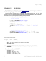
The ICSOFT is a Labview application running as a supervisory control application. It is based in
several GUIs and managers. The GUIs deal with the operator while the managers handle the remote
systems and SAM subsystems (RTSOFT, AOMSOFT, LMSOFT, and TCS). Remote client connections
are also allowed by means of communication server tasks.
SAMI
Eth
ICSOFT(LABVIEW)
Eth
SCL Server
(TCP/IP)
SOAR TCS
SCRIPTING
ENGINE
GUI TAB 1
Eth
Eth
(www.lua.org)
GUI TAB 2
GUI TAB 5
GUI TAB 3
GUI TAB 6
GUI TAB 4
Command Parser
LGS Control Mngr
(SCL Client)
Eth
LMsoft
RTC Manager
(SCL Client)
Eth
RTSOFT
AOM Control Mngr
(SCL Client)
TCS Manager
(SCL Client)
Eth
AOMSOFT
Eth
Figure 1: Block diagram of the Instrument Control Software. Managers handle the remote systems and AO
subsystems. Managers are TCP/IP clients using the SOAR Communication Library
The managers act as clients using the SOAR Communication Library (SCL) infrastructure. The
managers encapsulate all what's specific to each system/subsystem: status polling loops, command
routing, etc. All managers follow the same state machine logic; the manager keeps running while
connected to its server. If the connection is broken the manager enters the re-connection state until it reconnects or the application is terminated
The ICSOFT is capable of accepting remote commands from other systems acting as a server using
TCP/IP under SCL. The command interface is of the type: <command> <arg1> <arg2> ... <argN>.
3
ICSOFT Programmer Manual Rev 3.0, October 2010
Chapter 2: Software Architecture
The ICSOFT provides several GUIs. A command parser routes the local commands from the GUIs
and script engine, as well as remote commands received by the SCL server, to the managers for actions
and status information.
2.1 Source Code
The ICSOFT software can be found in the Instrument Control Computer machine, installed in the ao
user home directory /home/ao under root directory ICsoft. The Labview application code lives under
subdirectory modules with is main VI living alone in the root directory ICsoft.
Executables and shared libraries produced can be found under directory bin and lib. Configuration
files, data files under directory config.
Copies of the ICSOFT are kept in the SOAR public repository. Access is possible through local
accounts on machine ctioll. The path to the copies is /home/public/SOAR/SAM.
The following is a tree view of the directory structure of the software:
Icsoft
|--bin
|--config
|--data
|--doc
|--lib
|--logs
|--modules
| |--AOMLib
| |--AstroLib
| |--HistoryLib
| |--ICSoftLib
| |--LGSLib
| |--ParseLib
| |--RTCLib
| |--SCLN
| `--TCSLib
|--macro
`--scritps
To access the code is recommended to start by opening the main VI first
% cd /home/ao/ICsoft
% labview Icsoft.vi
2.1.1 Execution Threads
Table 1 lists the ICSOFT VIs and their execution thread and priority. The descendant VIs are all
marked to run in the execution thread of their parents.
ICSOFT Programmer's Manual Rev 3.0, October 2010
4
Chapter 2: Software Architecture
Table 1: Execution thread and priority assignments. Descendants are marked to run in the execution thread of their parents.
Vi Name
Queue
Running
1
Always
User Interface
Normal Main VI
hist_task
Always
User Interface
Normal Log alarms and events
parse_task
Always
User Interface
Normal Parse and execute string commands
icsoft_task_update_connections
Always
User Interface
Normal Poll for all remote connection status
ICsoft
Thread
Priority
Description
icsoft_task_command_servers
2, 3
Always
User Interface
Normal Incoming connections
icsoft_task_adc_logic
ADC
Always
Standard
Normal ADC corrections
tcs_task_manager_launcher
Mq1
Always
Data Acquisition Normal TCS manager
aom_task_manager_launcher
Mq2
Always
Data Acquisition Normal AOM manager
rtc_task_manager_launcher
Mq3
Always
Data Acquisition Normal RTC manager
lm_task_manager_launcher
Mq4
Always
Data Acquisition Normal LGS manager
5
ICSOFT Programmer Manual Rev 3.0, October 2010
Chapter 3: Scripting
Chapter 3:
Scripting
The ICSOFT integrates the LuaView engine (luaview.esi-cit.com) to handle scripting. For details on
the LUA scripting language visit the web site www.lua.org.
The LUA interface provides just two commands: sam.command and sam.wait_until_end. Read
section 3.1 below for a list of the available commands to be passed as arguments to the LUA interface.
Here is part of the GP1-tune.lua script for reference on how to use them
% cat /home/ICsoft/scripts/GP1tune.lua
-- Test GP1 centering
ok, flux = sam.command("GET RTC TT GP1F")
sam.command("LOG GP1flux is " .. flux)
fluxmin = 5.
if (flux + 0) < fluxmin then
sam.command("LOG Flux less than " .. fluxmin ..", returning")
return
end
.
.
.
-- Move the GP and take error signals
sam.command("LOG Moving probe to " .. x2 .. "
" .. y2)
sam.wait_until_end("AOM GUIDERP1 MOVE " .. x2 .." " .. y2, 25000)
ok, ex2 = sam.command("GET RTC TT GP1X")
.
.
.
3.1 Local Commands
ADC [MOVE | ENABLE | DISABLE]
MOVE - Use mount elevation to obtain prism angles
MOVE INNER OUTER
AOM
[GUIDERP1|GUIDERP2|TURSIM|WFS|ESHUTTER|ADC|OUTSEL|APD1|APD2|STATUS|
TELEMETRY]
Forwards commands to the AOMSOFT.
GUIDERP<N>
GUIDERP<N>
GUIDERP<N>
GUIDERP<N>
7
STOP
MOVE XP YP <ZP>
DIMMER [ON | OFF]
DIMMER MOVE [0-100]
ICSOFT Programmer Manual Rev 3.0, October 2010
Chapter 3: Scripting
TURSIM
TURSIM
TURSIM
TURSIM
TURSIM
TURSIM
TURSIM
WFS
WFS
WFS
WFS
PHSCREEN<N> MOVE [IN | OUT]
PHPLATE<N> MOVE [0-100]
INJARM MOVE [IN | OUT]
DIMMER [ON | OFF]
DIMMER MOVE [0-100]
SJOGX [0 | 1]
SJOGY [0 | 1]
FOCUS MOVE FP
REFBEAM MOVE [IN | OUT]
DIMMER [ON | OFF]
DIMMER MOVE [0 – 100]
ESHUTTER MOVE [OPEN | CLOSE]
ADC MOVE [IN | OUT | STOP]
ADC MOVE INNER OUTER
OUTSEL MOVE [IN | OUT]
APD<N> [ON | OFF | RESET]
ACAM [ON|OFF] – Turn the WFS acquisition camera power on-off.
HV [ON|OFF] – Turn the Pockel-Cell high voltage on-off.
STATUS
TELEMETRY
ECHO ARG1 ARG2 ...
Simply returns the arguments back to the originator
GET [RTC|AOMS|AOMT]
RTC
RTC
RTC
RTC
RTC
RTC
AOMS
AOMS
AOMS
AOMS
AOMS
AOMS
AOMS
AOMS
AOMS
AOMS
AOMS
AOMS
AOMS
RTC [FAULT|LSFAULT|SIMM]
WFS [RGATE|RGDELAY|STATUS|MIN|MAX|MEAN|STDEV|ETIME|MEANFLUX|BIAS|BGND]
AO [LOOP|LTIME|R0|V|VCM]
TT [LOOP|CTLR|FULLBW|LTIME|GP1F|GP2F|GP1W|GP2W|GP1X|GP1Y|GP2X|GP2Y]
MOUNT [LOOP]
LLT [LOOP|CTLR]
Guider_P1_X [position|pos_zpoint|status]
Guider_P1_Y [position|pos_zpoint|status]
Guider_P2_X [position|pos_zpoint|status]
Guider_P2_Y [position|pos_zpoint|status]
Focus_P1 [position|status|init]
Focus_P2 [position|status|init]
G_Dimmer_P1 [power|status|dimmer]
G_Dimmer_P2 [power|status|dimmer]
Output_Selector [position|status|abs_position|trajectory|init]
TS_Ph_Screen_1 [position|status|abs_position]
TS_Ph_Screen_2 [position|status|abs_position]
TS_Source_Adj_X [position|status|abs_position]
TS_Source_Adj_Y [position|status|abs_position]
ICSOFT Programmer's Manual Rev 3.0, October 2010
8
Chapter 3: Scripting
AOMS
AOMS
AOMS
AOMS
AOMS
AOMS
AOMS
AOMS
AOMS
AOMS
AOMS
AOMS
AOMS
AOMS
AOMS
AOMS
TS_Dimmer [power|status|dimmer]
TS_Phase_Plate [ph_plate1_status|ph_plate1_vel]
TS_Phase_Plate [ph_plate2_status|ph_plate2_vel]
TS_Phase_Screen [screen1_pos|screen2_pos|power1|power2|status1|status2]
TS_Source_Adj [s_adjx_status|s_adjy_status|sourcex_vel|sourcey_vel]
TS_Inj_Arm [position|power|status]
Filter_Wheel [position|status]
WFS-Focus [position|status|abs_position|init]
WFS_Ref_Beam [position|power|status]
WFS-Dimmer [power|status|dimmer]
ADC-Inner [position|status|init]
ADC-Outer [position|status|init]
ADC_Position [position|abs_position|status|init]
Fabri-Perot [position|abs_position|status|init]
Sam_Cover [position|status]
SHUTTER [position|status]
AOMT PowerSupply [Telemetry|APD1_30V|APD2_30V|APD_5V|APD_2V|Reserved_01]
AOMT PowerSupply [Prosilica_12V|Prosilica|Reserved_03|Control|APD1|APD2]
AOMT PowerSupply [Overcurrent_APD1| Overcurrent_APD2]
AOMT HV [Pockels_Power_supply|HV_value|HV_Error]
AOMT HV [status]
AOMT Temperatures [Glycol|OAP1_area|DM_area|OAP2_area|ADC_area|Tursim_area]
AOMT Temperatures [status]
INFO
This command will return a string of the form “DONE VAR1=VAL1 VAR2=VAL2” containing
status information of the SAM instrument. The data included is
OPMODE
R0
WSPEED
VARCM
INSTRMT
DMLOOP
FTIME
WFSFLX
WFSFOC
M3LOOP
APDTIME
APDHV
P1LIGHT
P2LIGHT
MNTLOOP
LLTLOOP
RGPOWER
RGDELAY
LGSDIST
LQUALTY
LPOWER
9
SAM operation mode: TSNGS, NGS, TSLGS or LGS
Estimated Fried parameter in [m]
Estimated wind speed in [m/s]
Variance of corrected modes in [rad^2]
Name of selected instrument: SAMI, VISITOR, etc.
DM mirror loop ON or OFF
Frame time in [ms]
WFS flux in [Ke-/s] per sub-aperture
WFS focus in [mm]
M3 mirror loop ON or OFF
APDs sample time in [ms]
APDs high voltage ON or OFF
Guide probe 1 light ON or OFF
Guide probe 2 light ON or OFF
Mount loop ON or OFF
LLT loop ON or OFF
Range gate power ON or OFF
Range gate delay in [ns]
Laser guide star distance in [Km]
Laser quality
Laser power ON or OFF
ICSOFT Programmer Manual Rev 3.0, October 2010
Chapter 3: Scripting
LSHUT
LLTDOOR
ADC
ADCIN
ADCOUT
VIFOLD
REFLIGHT
REFARM
TSDISK
TSFOLD
TSLIGHT
MODDOOR
LOG
Laser intra cavity shutter OPEN or CLOSE
Launch laser telescope environmental door OPEN or CLOSE
ADC compensation ON or OFF
ADC inner element position
ADC outer element position
Visitor instrument fold IN or OUT
WFS reference light ON or OFF
WFS reference arm IN or OUT
TURSIM disk rotation ON or OFF
TURSIM fold IN or OUT
TURSIM light ON or OFF
Environmental module door OPEN or CLOSE
ARG1 ARG2 ....
Log the arguments to the ICSOFT log file and to the Events and Messages display.
RTC
Forwards commands to the RTSOFT
AO [OPEN | CLOSE]
BGND [ON | OFF]
BIAS [ON | OFF]
CAMERA [exposure|ldf|power|readout|reset|set|mancmd]
exposure [stop|abort]
ldf [util|pci|tim]
power [on|off]
readout[abort|stop-idle]
set binning <val1> <val2>
set exposure <val>
set frames <val>
set gs <val1> <val2>
set readout <val>
set size <val1> <val2>
set trigger <val>
set roi <val1> <val2> <val3> <val4>
set panoramic]
ECHO
EXEC <Script>
FLATTEN – flatten DM
LLT [OPEN|CLOSE|ENABLE|DISABLE]
LOAD [apdmap|wmat|xgrid|ygrid] <filename>
M3 [CLOSE|DISABLE|ENABLE|OPEN]
MODE [TSNGS|NGS|TSLGS|LGS] – set RTC operation mode
MOUNT [OPEN|CLOSE]
RMFAULT - clear alarms
RNOISE
- set readout noise value
RT
- RTCORE interface
SDSU
- LEACHIII interface
SETREF
- reset references
SLEEP <val> - wait a number of milliseconds
SYSTEM
- RTC system command
ICSOFT Programmer's Manual Rev 3.0, October 2010
10
Chapter 3: Scripting
TCS
Forwards command to the TCS.
3.2 Remote Commands
These are command available only to remote applications connecting to the ICSOFT through one of
its three command servers. Two of the servers have at their core the parse-service-instrumentcommand.vi. The third one is GMAP1 specific and implemented by the parse-service-gmapcommand.vi.
3.2.1 Instrument Command Handler
Default behavior is to forward the command to the ICSOFT command parser in parse_task.vi and
return immediately with the response.
AO [OPEN | CLOSE] - Open/Close the AO loop by executing the script
aoloop_close.lua and aoloop_open.lua
AOM [P1 | P2] - Return the current X-Y coordinates for guide probe 1 or 2.
ECHO - see section 3.1 above for a complete description.
GET - see section 3.1 above for a complete description.
INFO - see section 3.1 above for a complete description.
PING - replies the string “SAM INSTRUMENT CONTROL APPLICATION”
3.2.2 GMAP Command Handler
ECHO - see section 3.1 above for a complete description.
GC - Returns the current RA-DEC mount coordinates.
GP - Returns the current Rotator Mechanical Angle.
P1 [XYSTATUS | COORDS]
P2 [XYSTATUS | COORDS]
XYSTATUS - X-Y coordinates of guide probe 1 in arc-seconds using the
GMAP X-Y reference system. In that frame XGMAP is flipped with respect
to XSAM. The XYSTATUS command account for that flip and returns the
correct sign to GMAP.
COORDS HH:MM:SS DD:MM:SS Epoch – Set the ICSOFT next object RA-DEC1 Guide Star Selection Tool
11
ICSOFT Programmer Manual Rev 3.0, October 2010
Chapter 3: Scripting
EPOCH variables. The next object coordinates can be then be used for
guide star acquisition see section TBD.
ICSOFT Programmer's Manual Rev 3.0, October 2010
12
Chapter 4: Guide Star Acquisition
Chapter 4:
Guide Star Acquisition
Guide star acquisition involves transforming RA-Dec coordinates to X-Y stages coordinates in
[mm]2. The required functionality for doing the transformations is provided by the ASTROLIB library
of VIs. The library was contributed by SOAR and is part of the SOAR TCS application suite.
The ICS accepts target coordinates for the probe expressed in RA-Dec plus epoch. The
transformations are encapsulated in icsoft_general_GRA_GXY.vi. The VI accepts as input the target
RA-Dec coordinates and returns as output the X-Y coordinates of the guide star.
An important assumption is made based on the way the other guider stages at SOAR operate. When
a guide probe is at 0,0 that position matches the telescope pointing after a Zero point calibration. This is
true for all guiders at SOAR and SAM is consistent with that [TBD IF TRUE].
The process starts by moving the input coordinates to the epoch reported for the TCS telescope
coordinates. The resulting RA-Dec coordinates along with the TCS coordinates are used to obtain the
gnomonic projection coordinates and ( is in the east axis and is in the north axis).
Then the transformations that account for the optical system of the telescope are applied [see Error:
Reference source not found and below]. Here those transformation are presented in their matrix form
[] [
][
][
][
][ ]
x = cos ROT −sin ROT cos −EL −sin −EL −1 0 cos −sin
y
sin ROT cos ROT sin−EL cos −EL 0 −1 sin cos
Finally, the coordinates in units of [mm] are obtained multiplying x and y by the focal length of the
telescope.
2 Looking SAM from the ISB, X is parallel to the bench and positive right. Y is perpendicular to the bench and positive
up.
13
ICSOFT Programmer Manual Rev 3.0, October 2010
Chapter 5: Atmospheric Dispersion Correction
Chapter 5:
Atmospheric Dispersion Correction
The ADC task is implemented by the icsoft_task_adc_logic VI. The VI loops waiting for input in the
ADC Task Queue . If the MOVE command arrives, the task searches for two arguments containing the
target positions for the prisms. The arguments are used to build the command “AOM ADC MOVE ARG1 ARG2” and the resulting string is then sent to the AOMSOFT.
If the GO command arrives instead, the task uses the current telescope elevation (EL) and Nasmyth
rotator mechanical angle (ROT), as stated by the TCS, to obtain the target position for the prisms. The
process starts in the VI icsoft_calculate_dispersion_angle by obtaining the dispersion orientation angle
(DA) for the ADC [see Error: Reference source not found Error: Reference source not found].
The dispersion orientation angle along with the zenith distance (ZD = 90 - EL) is then passed to the
VI icsoft_compute_adc_elements_position to obtain the final target positions for the inner element
(INNER) and the outer element (OUTER) of the ADC as
if (STRENGTH*tan(zd) < 1)
ANGLE = 90.0 - RAD2DEG( asin(STRENGTH*tan(zd)) );
else
ANGLE = 90.0
DA
= DA0 * SIGN + OFFSET;
INNER = DA – ANGLE;
OUTER = DA + ANGLE;
The two angles are then used to build the command “AOM ADC MOVE INNER OUTER” and the
resulting string is sent to the AOMSOFT. OFFSET, SIGN and STRENGTH are user defined parameters
obtained from the icsoft.ini configuration file.
When ADC compensation is enabled, the GO command executes every TIMEOUT seconds,
triggered by a loop in the VI icsoft_task_control_manager. TIMEOUT is a user defined parameter
obtained from the icsoft.ini configuration file.
15
ICSOFT Programmer Manual Rev 3.0, October 2010
Chapter 6: Telemetry
Chapter 6:
Telemetry
The icsoft_task_telemetry VI runs every second and checks for every test-point if LTIME seconds
have elapsed since the last check. The list of test-points to check is defined in the telemetry.ini file and
LTIME is a test-point user defined parameter.
Each test-point in the telemetry.ini file has an ID. The assignment between ID and telemetry channel
is hardwired into the code (Table 2)
Table 2: Test-point ID assignments
ID
17
Global Variable
Telemetry Keyword
0
TCHANNEL 00
30V Power Supply
1
TCHANNEL 01
30V APD 1
2
TCHANNEL 02
30V APD 2
3
TCHANNEL 03
5V APD
4
TCHANNEL 04
2V APD
5
TCHANNEL 05
Glycol
6
TCHANNEL 06
OAP1
7
TCHANNEL 07
DM
8
TCHANNEL 08
OAP2
9
TCHANNEL 09
ADC
10
TCHANNEL 10
TURSIM
11
TCHANNEL 11
PROSILICA 12V
12
TCHANNEL 12
Pockels-Cell High-Voltage
ICSOFT Programmer Manual Rev 3.0, October 2010
APPENDIX A: North-East coordinates to Up-Left coordinates for Gnomonic Projection
APPENDIX A: North-East coordinates to Up-Left
coordinates for Gnomonic Projection
+
Up
North
ξ
θ
η
Left
East
Figure 2: View of the celestial sphere from the outside. is the angle between the plane containing the major circle
of the reference RA and major circle of the reference AZ.
The east-north coordinates ( is east) for the gnomonic projection of an object ( ) near the
reference coordinate (Z , Z) is given by
cos c = sinsin Z cos cos Z cos−Z
=
cos sin−Z
cos c
=
sin cos Z – cos sin Z cos−Z
cos c
(1)
To move the above coordinates to the Up-Left reference frame, they have to be rotated by the angle
between the North and Up vectors. That angle is obtained using the following algorithm for a given
geographic latitud , refence declination Z and reference hour angle H
z = cos, 0, sin , m
= cos −H cos Z , sin −H cos Z , sin Z , p = 0, 0, 1
Vector z is the zenith, m is the reference and p is the pole. Vector l is the normal vector defining the
plane containing the major circle of AZ. Vector e is the normal vector defining the plane containing the
major circle of RA.
Using the cross and dot product between the two normal we obtain the tangent of angle .
ICSOFT Programmer's Manual Rev 3.0, October 2010
18
APPENDIX A: North-East coordinates to Up-Left coordinates for Gnomonic Projection
l = z × m
e = p × m
∥l × e∥
l ⋅ e
tan =
(2)
m
⋅ l × e 0 ⇒ = 2 −
[
Then, the transformation is obtained by multiplying the north-east coordinates by the rotation matrix
cos −sin
.
sin
cos
19
ICSOFT Programmer Manual Rev 3.0, October 2010
]
APPENDIX B: Up-Left coordinates to SAM Guide Probe coordinates
APPENDIX B: Up-Left coordinates to SAM Guide
Probe coordinates
Up
Left
y ISB
x ISB
y GP
x GP
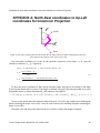
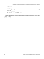
Figure 3: Telescope pointing to the horizon and rotator angle 0o.
Up
The image to the left is an image of the spider. The reference axes
match the alt-azimuth telescope Up and Left reference frame. Colored
lines has been added to better visualize the flips and rotations introduced
by the telescope optical system.
Left
Up
The M1 primary mirror introduces a vertical and a horizontal flip and
the M2 secondary mirror introduces no change. The transformation is
−1 0
obtained by multiplying the x-y coordinates by
.
0 −1
[
]
Left
21
ICSOFT Programmer Manual Rev 3.0, October 2010
APPENDIX B: Up-Left coordinates to SAM Guide Probe coordinates
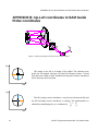
270°
180°
ISB
SAM
0°
90°
Figure 4: When the rotator angle is 0° SAM points to the right. Changes in rotator position
introduce a rotation in plus the rotator angle ROT. ROT [0°, 360°].
yISB
To reference the M3 tertiary mirror effect, we use reference axes fixed
to the ISB [Figure 3]. With the elevation ring pointing to the horizon
(EL=0°) and the Nasmyth rotator (ROT) at its 0° angle position, M3
introduces no change.
xISB
yISB
Changes in
angle. The
cos −EL
sin−EL
[
elevation introduce a rotation in minus telescope elevation
transformation is obtained by multiplying by
−sin −EL
, with EL [0°, 90°].
cos −EL
]
xISB
ICSOFT Programmer's Manual Rev 3.0, October 2010
22
APPENDIX B: Up-Left coordinates to SAM Guide Probe coordinates
yISB
Changes in rotator position introduce a rotation in plus the rotator
angle. The transformation is expressed by multiplying by
cos ROT −sin ROT
, with ROT [0°, 360°].
sin ROT cos ROT
[
]
xISB
yGP
To reference the M4 flat mirror effect, we use the reference axes of the
SAM guide probes. With the elevation ring pointing to the horizon
(EL=0°) and the Nasmyth rotator (ROT) at its 0° angle position, M4
introduces no change.
xGP
23
ICSOFT Programmer Manual Rev 3.0, October 2010
APPENDIX C: Dispersion Orientation Angle
APPENDIX C: Dispersion Orientation Angle
360°
y GP
x GP
90°
270°
180°
Figure 5: A final transformation is necessary to match the ADC mechanism convention for its
prism angles.
The dispersion orientation angle (DA) matches the Down axis of the telescope at all times, that is (0,
-1) in Up-Left coordinates. Applying the transformations explained in the previous appendix it is
possible to obtain its position over SAM focal plane in XGP-YGP coordinates as
[ ] [
][
][
][ ] [
DA x
= cos ROT −sin ROT cos −EL −sin−EL −1 0 0 = −sin ROT −EL
sin ROT cosROT sin−EL cos−EL 0 −1 −1
cos ROT −EL
DA y
]
Light goes behind the SOAR focal plane, reflects in OAP1, then goes down and to the right, reflects
in the deformable mirror and hits the ADC. The net effect is only a small fixed rotation of ~2° degrees.
The dispersion angle can be obtained using an ATAN2(DAy, DAx) type of function, to obtain a
solution in the range [-180°, 180°]. A final transformation is necessary to match the ADC convention
for the prism angles (see Figure 5)
DA ADC = 90 ° − DA GP
25
(3)
ICSOFT Programmer Manual Rev 3.0, October 2010