1
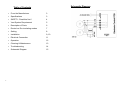
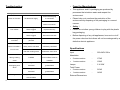
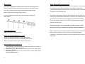
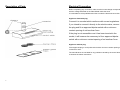
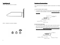
DESIGNER SLIM HOOD
For original parts & reliable service :
USER MANUAL
INSTALLATION INSTRUCTIONS
Schematic Diagram
Table of Contents
2
•
From the Manufacturer
3
•
Specifications
3
•
SAFETY : Read this first !
4
•
Vent System Requirement
5
•
Description of Parts
6
•
Ducted vs. Re-circulating modes
7
•
Setting
8
•
Installation
9, 10
•
Electrical Connection
11
•
Operation
12
•
Cleaning & Maintenance
13
•
Troubleshooting
14
•
Schematic Diagram
15
15
Troubleshooting
Symptoms
Possible Cause
•
From the Manufacturer
•
This appliance and it’s packaging are produced by
processes that minimize waste and respect the
Action
environment.
Check that the plug
Does not fucntion
No electrical supply
•
Please help us to continue the protection of the
Check that the main
environment by disposing of the packaging in a correct
switch is turned on.
manner.
Aluminium grease
Clean the filters and
•
Safety !
filters clogged
replace when dry
•
Please do not allow young children to play with the plastic
Charcoal grease
Replace charcoal
filters clogged
filters with new sets
Motor running but
Butterfly valve
Contact technician
no airflow
jammed
Poor airflow
bag packaging.
•
Before disposing of any old appliances, be sure to cut off
the power chord so that others will not be endangered by a
defective electric appliance
High temperature
The kitchen is not
Motor cuts after a
safety device activated
sufficiently ventilated
few minutes
The hood is installed too
The hood must be
near the cooking stove
least 65cm from stove
Input
Charcoal filters not
In re-circulating mode,
Absorbtion
installed
charcoal filters must be
Strong cooking
smell
Oil dripping onto
stove
Whirring sound
installed
Alluminium grease filter
Wash the alumnium
saturated
grease filters
Aluminium grease filter
Wash the alumnium
saturated
grease filters
Foreign object in contact
Contact technician
with fan blade
14
is connected.
Specifications
:
220-240V 50Hz
•
2 motor version
:
170W
•
1 motor version
:
105W
:
2 X 20W
Lamps
Total Power
•
2 motor version
:
210W
•
1 motor version
:
145W
External Dimensions
3
SAFETY : Read this First !
Cleaning & Maintenance
•
Do not connect the appliance if there are obvious signs of transportation
SURFACES : Wash with warm soapy water and a soft sponge. Never use
damage.
abrasive detergent, scouring pads, steel wool or solvents on any part of this
Read this user manual thoroughly before attempting to use this
appliance as this will cause irreparable damage.
•
appliance.
•
Installation and repair should be attempted only by qualified technical
GREASE FILTERS - Maybe one of the following:
personnel.
Aluminium Grease Filters : Wash in the dishwashers or soak the panels in a
•
It is dangerous to modify any part of this appliance.
degreasing agent for an hour, then rinse off.
•
The manufacturer declines all responsibility in case of failure to adopt
Baffle Filters : The baffle grease filters should be cleaned frequently in hot
proper safety measures.
detergent solution or washed in the dishwasher. Clean exterior surfaces with
Ensure the location in which this appliance is installed has good,
a commercially available stainless steel cleaner. Abrasives and scouring
permanent ventilation.
agents can scratch stainless steel finishes and should not be used to clean
The distance between the bench top to the lower part of the hood must
finished surfaces.
•
•
not be at less than 65 cm or higher than 75 cm.
•
Use an electrical connector with earth that is correct for your location.
CHARCOAL FILTERS (only in re-circulating model) : Charcoal cannot be
•
Check that the voltage in your area is correct before plugging in.
reused. They must be replaced with the appropriate types once a year or
•
The electrical connection of this appliance must be connected to earth.
depending on the frequency of appliance usage.
•
•
•
Green & yellow
=
EARTH
For this appliance to function effectively, regular maintenance is a must.
Blue
=
NEUTRAL
Clogged filters restrict airflow and may cause the motor to overheat.
Brown
=
LIVE
Multiple plugs and extension cables must not be used. Overload is
LIGHT BULB REPLACEMENT : Before attempting to replace the light bulb,
dangerous and may cause a fire.
make sure that the light switch is turned off. Remove the grease filter to
Ensure that the power supply chord is free from any heat source or
access the lamp area. Remove the damaged light bulb and replace with an
sharp objects.
incandescent oval bulb maximum 40W.
The appliance should be switched off and the electrical supply
disconnected before any cleaning or maintenance work can be carried
out.
4
13
Operation
Vent System Requirements
The hood is equipped with 3 speed control. Electronic control buttons are
located on the front edge of the range hood canopy or enrichment panel.
Determine which venting method is best for your application. Vented (non-
Use the low speed for simmering, medium speed for light cooking.
Use the high speed for frying or heavy cooking.
recirculating) system must be terminate to the outside. Ductwork can
extend either through the wall or the roof. Do not terminate the vent system
in an attic or other enclosed area.
It is also equipped with a light bulb to illuminate your cooking area
The length of the ductwork and the number of elbows should be kept to a
when needed.
minimum to provide efficient performance. The size of the ductwork should
be uniform. Do not install two elbows together. Use duct tape to seal all
joints in the ductwork system. Use caulking to seal exterior wall or floor
opening around the cap.
Flexible ductwork is not recommended. Flexible ductwork creates
back pressure and air turbulence that greatly reduces performance.
Light On/Off Button (i)
Make sure there is proper clearance within the wall or floor for exhaust duct
Switch the lighting system on and off.
before making cutouts. Do not cut a joist or stud unless absolutely
Blower On and Speed Buttons ( ii, iii & iv)
Button (ii) operates the blower on LOW speed and off.
necessary. If a joist or stud must be cut, then a supporting frame must be
constructed.
Button (iii) operates the blower for MEDIUM speed and off.
Button (iv) operates the blower for HIGH speed and off.
Clock and delay timer displayer (x)
1. Push light button for a few second to set delay timer with 3-15 minutes (3
minutes increment) when hood was on.
2. Push button (ii) for a few second to set the clock for hour display when
selected LOW speed.
3. Push button (iii) for a few second to set the clock for minute display when
selected MEDIUM speed.
12
5
Description of Parts
Electrical Connection
Before completing any connection, make sure the house voltage corresponds
with the voltage indicated on the label affixed inside the hood.
It is advisable to call a qualified technician to make the electrical connection.
Appliance fitted with plug
Connect it to a socket which conforms with current regulations.
If you intend to connect it directly to the electric mains, remove
the plug and fit an approved bipolar switch with a minimum
contact opening of not less than 3mm.
If the plug is not accessible once it has been inserted in the
socket, it will however be necessary to fit an approved bipolar
switch with a minimum contact opening of no less than 3mm.
Appliance without plug
Fit an approved plug or an bi-polar switch with a minimum contact opening of
no less than 3mm.
The manufacturer are not liable for any problems caused by the user’s failure
to observe the above instructions
6
11
Installation (2)
Ducted vs. Re-circulating
STEP 3 : Hang the hood on the 2 screws.
Your cooker hood can be configured to operate in the ducted or re-circulating
mode :A. DUCTED MODE (VENTED MODE)
•
In the ducted mode, cooking fumes are vented outdoors through suitable
connection of 125mm diameter. In this mode, only the aluminium filters
are installed.
STEP 4 : Tighten the 2 screws completely.
B. RE-CIRCULATING MODE
•
Fumes are filtered for grease and odour through the aluminium grease
filters and the charcoal filters respectively and re-introduced into the
kitchen environment. In re-circulating mode, both the aluminium grease
filters and the charcoal filters must be installed.
10
7
Setting
Installation (1)
The operating mode of your cooker hood must be set before installation
STEP 1 : Remove the aluminum filters and place them in a safe location to
avoid damage.
A. To set your hood to operate in the ducted mode
•
remove the aluminium grease filters and locate the 2 setting
screws
•
Turn the screws clockwise until locked.
•
Install the outlet connector the back or top outlet and the stopper
in the other.
•
Remove the charcoal filters if installed.
STEP 2 :
Install the 2
screws on the
wall.
B. To set your hood to operate in the re-circulation mode
•
remove the aluminium grease filters and locate the 2 setting
screws
8
•
Turn the screws anti-clockwise until released.
•
Install the stoppers in the top and back outlets.
•
Install the charcoal filters if not already done so.
9