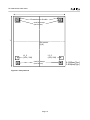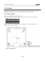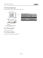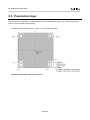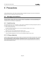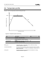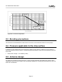
1
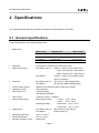
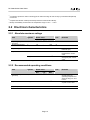
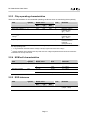
Card IC RC-S966 Series Data Sheet Version 1.2 No. M751-E01-20 RC-S966 Series Data Sheet Introduction This document describes major function of RC-S966 series (i.e. RC-S966/1A, RC-S966/1C, and RC-S966/1S, hereinafter referred to as “RC-S966”), a chip for the contactless IC card that uses Sony's FeliCa technology. RC-S966 supports commands that FeliCa Lite-S products need. You are advised to read this document if you are responsible for manufacturing of products which uses contactless IC card chip. The authors assume that readers of this document are familiar with contactless IC card technology, electronic circuit and integrated circuit. FeliCa is a contactless IC card technology developed by Sony Corporation. FeliCa is a trademark of Sony Corporation. All names of companies and products contained herein are trademarks or registered trademarks of the respective companies. No part of this document may be copied, or reproduced in any form, without the prior consent of Sony Corporation. Information in this document is subject to change without notice. Sony Corporation assumes no liability for damages arising from, or in connection with, the use of this document. Page 3 RC-S966 Series Data Sheet Cautions Responsibility for quality assurance, defect warranties and other items relating to individual transactions shall conform to these sales contracts and other adjunct contracts concluded between the Sony Sales Department or Sony agents and customers, and this Data Sheet shall not in any way add to or modify the contents of said contracts. Sony makes the utmost efforts to improve the quality and reliability of its products, but semiconductor failure of a certain percentage is unavoidable. Therefore, we request that sufficient care be given to ensuring safe design in customer products such as redundant design, anti-conflagration design and design for preventing misoperation in order to prevent accidents resulting in injury or death, fire or other social damage from occurring as a result of semiconductor failure. In addition, be sure to consult your Sony sales representative beforehand when there is a chance that customer products manufactured using Sony products may pose a life- or injury-threatening risk or are highly likely to cause significant property damage in the event of such a failure. Sony reserves the right to change the contents of this Data Sheet without notice. Be sure to check the latest information before using Sony semiconductor products. Technical materials shown in this Data Sheet do not convey any license by any implication or otherwise under any Sony or third party patents or other rights, and Sony cannot assume responsibility for any problems arising out of the use of this information or for any infringement of patent or other right due to same. Export of products noted in this Data Sheet which fall under the category of regulated commodities as prescribed by the Foreign Exchange and Foreign Trade Control Act requires approval under said Act. The contents of this Data Sheet may not be reproduced or transferred in any form, in part or in their entirety, without the express written permission of Sony Corporation. Page 4 RC-S966 Series Data Sheet Contents 1 Major functions and features ...................................................................................................... 7 2 Specifications............................................................................................................................... 9 2.1 General specifications ........................................................................................................................... 9 2.2 Electrical characteristics...................................................................................................................... 10 2.2.1 Absolute maximum ratings ........................................................................................................ 10 2.2.2 Recommended operating conditions ......................................................................................... 10 2.2.3 Chip operating characteristics ................................................................................................... 11 2.2.4 NVM cell characteristics ............................................................................................................ 11 2.2.5 ESD tolerance............................................................................................................................ 11 3 Internal configuration ................................................................................................................ 12 4 File system and command ........................................................................................................ 13 4.1 File specification .................................................................................................................................. 13 4.2 Service ................................................................................................................................................ 14 4.3 Command list ...................................................................................................................................... 15 4.4 Command parameters specific to RC-S966 ....................................................................................... 16 5 Security ....................................................................................................................................... 17 6 Die geometry .............................................................................................................................. 18 6.1 Pads .................................................................................................................................................... 18 6.1.1 Number of pads ......................................................................................................................... 18 6.1.2 Pad material ............................................................................................................................... 18 6.1.3 Pad positions ............................................................................................................................. 18 6.2 Bumps ................................................................................................................................................. 20 6.2.1 Bump position ............................................................................................................................ 20 6.2.2 Bump dimensions ...................................................................................................................... 21 6.2.3 Bump material............................................................................................................................ 21 6.2.4 Bump hardness.......................................................................................................................... 21 6.3 Passivation layer ................................................................................................................................. 22 6.4 Die thickness ....................................................................................................................................... 23 6.5 Die dimensions .................................................................................................................................... 23 6.6 Characters on die ................................................................................................................................ 23 7 Packing specifications .............................................................................................................. 24 7.1 Packing specifications for sawn wafers on wafer rings ....................................................................... 24 7.1.1 Wafer ring .................................................................................................................................. 24 7.1.2 Inner carton ................................................................................................................................ 26 7.1.3 Outer carton package ................................................................................................................ 29 7.1.4 Identification of defective dies ................................................................................................... 31 7.1.5 Maximum quantity of dies on a wafer ........................................................................................ 31 7.1.6 Yield of wafer ............................................................................................................................. 31 7.2 Packing specifications for unsawn wafers .......................................................................................... 32 7.2.1 Wafer ......................................................................................................................................... 32 7.2.2 Inner carton ................................................................................................................................ 33 7.2.3 Outer carton package ................................................................................................................ 35 7.2.4 Identification of defective dies ................................................................................................... 38 7.2.5 Maximum quantity of dies on a wafer ........................................................................................ 38 7.2.6 Yield of wafer ............................................................................................................................. 38 8 Precautions ................................................................................................................................ 39 8.1 Storage precautions ............................................................................................................................ 39 8.1.1 Shelf life of die ........................................................................................................................... 39 8.1.2 UV tape adhesivity ..................................................................................................................... 39 8.2 Temperature profile ............................................................................................................................. 40 8.3 Bonding precautions ........................................................................................................................... 41 8.4 Pressure applicable to the chip surface .............................................................................................. 41 Page 5 RC-S966 Series Data Sheet 8.5 Antenna design ................................................................................................................................... 41 8.6 Handling precautions .......................................................................................................................... 42 8.7 External appearance of a sawn wafer ................................................................................................. 42 9 Dicing an unsawn wafer ............................................................................................................ 43 Appendix A FeliCa Terminology .................................................................................................. 44 A.1 Abbreviation ........................................................................................................................................ 44 A.2 Glossary .............................................................................................................................................. 44 Page 6 RC-S966 Series Data Sheet 1 Major functions and features RC-S966 is a contactless IC card chip, based on Sony’s FeliCa technology. The features of RC-S966 are described below. Lower price With simplified security functionality and an optimized file system, RC-S966 is offered at lower prices than conventional FeliCa chips (hereinafter referred to as “FeliCa Standard chips”). RC-S966 are suited for embedding in such low-cost products as sales promotion articles, membership cards, points cards, game cards, gift cards, and multi-use ticket. Use of existing FeliCa infrastructure RC-S966 is based on the same wireless communication method as conventional FeliCa Standard-compatible products and a command system compatible with that for conventional FeliCa Standard chips. Therefore, you can use your existing infrastructure, including FeliCa ports, and development environment without change. You can issue and operate RC-S966 with only three commands: Polling, Read Without Encryption, and Write Without Encryption. Mutual authentication function RC-S966 has a mutual authentication function, which is different from that in conventional FeliCa Standard chips, for authentication with the Reader/Writer. This function is suited for applications such as ID and Points cards. Detection of falsification RC-S966 can detect falsification by adding MAC (Message Authentication Code) to the data read out and written in. Compliance with NFC Forum Type 3 Tag RC-S966 is compliant with the Type 3 Tag defined by the NFC Forum. Therefore, they can communicate with any Reader/Writer that is compliant with the NFC Forum standard. The RC-966 can be used for Handover and Smart Poster applications. Reduction in chip size RC-S966 has succeeded to achieve smaller chip size (0.99mm x 0.99mm (Typ.), after dicing) by adopting a fine process technology and only the command set of the minimum requirement, with suppressed memory capacity. Communication system The communication system of RC-S966 is based on inductive coupling. Page 7 RC-S966 Series Data Sheet Power-saving design RC-S966 is a low-power consumption designed chip. All significant functions of FeliCa contactless IC card are implemented into RC-S966, except antenna circuitry. Because RC-S966 can operate at a low electromagnetic field density, you can use RC-S966 for stickers, smart posters, and other non-card media that have miniaturized antennas. High data reliability RC-S966 has highly-reliable NVM (Non-Volatile Memory) inside the chip. Write cycle endurance of memory cells is 50,000 when chip is used at Tj*1 = 25°C, or 10,000 when used at Tj = 85°C. *1 Tj stands for Junction temperature. IDm RC-S966 has chip-unique IDm written in its NVM, which is written at the time of shipment. Data transfer rate RC-S966 supports automatic data transfer rate switching between fc*1/64 (approx. 212kbps, hereinafter referred to as “212kbps”) and fc/32 (approx. 424kbps, hereinafter referred to as “424kbps”) . *1 fc stands for frequency of carrier signal (13.56MHz). Simple file system Data can be written in block (16-byte) units into the on-chip memory of RC-S966. The adaption of a non-hierarchical file system enables access to blocks using only a single service. Each block can be set: o o o to be write-protected whether or not authentication is necessary when the data is written-in to/read out of the block whether or not MAC is necessary when the data is written in to the block Data protection function against power interruption (anti-tearing) In RC-S966, the function to guarantee the data integrity at the command level is implemented. If data write to NVM is interrupted due to power failure, the data is replaced by the previously stored data. See "FeliCa Lite-S User's Manual" for detailed descriptions. Page 8 RC-S966 Series Data Sheet 2 Specifications This chapter describes general specifications and electrical characteristics of RC-S966. 2.1 General specifications General specifications of RC-S966 are listed below. Model name : Model name Shipping form Pad or bump*1 RC-S966/1A Sawn wafer on wafer ring Bump on pad RC-S966/1C Sawn wafer on wafer ring Pad RC-S966/1S Unsawn wafer Bump on pad Application : Contactless IC card based on FeliCa technology External dimensions : RC-S966/1A and /1C 0.99mm×0.99mm (Typ.) (After dicing) (Face) 980 (±50) µm x 980 (±50) µm (Back) 995 (±50) µm x 995 (±50) µm RC-S966/1S 1.08mm×1.08mm (Typ.) (Before dicing) (Size of die pattern) Thickness : RC-S966/1A and /1C RC-S966/1S Communication system : Wireless communication based on inductive coupling*2 Modulation system : ASK modulation Data transfer rate : 212kbps/424kbps automatically switchable User memory : 14 Blocks (1 Block = 16 Bytes) NVM cell performance : Data retention period : 10 years 5 years Rewriting durability : 50,000 times (at Tj = 25°C) 10,000 times (at Tj = 85°C) Shipping form : RC-S966/1A and /1C RC-S966/1S Operating temperature : -25°C to +100°C*3 Storage temperature : -55°C to +125°C Minimum operating current : 500µA (max.) Page 9 120 (±15) µm (After backgrinding) 725 µm (Typ.) (Before backgrinding) (at Tj = 25°C) (at Tj = 85°C) Sawn wafer on wafer ring (8”) Unsawn wafer (8”) RC-S966 Series Data Sheet *1 A conductive protrusion made on bonding pad for interconnecting die and circuitry by Controlled Collapse Chip Connection. *2 Complies with ISO/IEC 18092 (212/424 kbps Passive Communication Mode). *3 Quality and reliability are assured in the temperature range of -25°C ~+85°C 2.2 Electrical characteristics 2.2.1 Absolute maximum ratings *1 Item Symbol Rated value Unit Min. Typ. Max. Operating temperature (junction) Storage temperature Tj -40 - +125 °C Tstg -55 - +125 °C Input voltage Vain - - 15 V0p Input current Iain - - 191 mApeak Iain_avg - - 74.2*1 mA Remarks Between antenna terminals (AC) Antenna terminal instantaneous current value Antenna terminal average of peak current value Under the condition that carrier signal of 13.56MHz sine wave is inputted. 2.2.2 Recommended operating conditions *1 Item Symbol Rated value Unit Remarks Min. Typ. Max. Operating temperature (junction) Tj -25 - +100 °C 66*1 mA Quality and reliability are assured when the operating temperature is within the range of -25°C to 85°C Antenna terminal average of peak current value Input current Iain_avg 0.5 - Input frequency fc 13.56 MHz - - Under the condition that carrier signal of 13.56MHz sine wave is inputted. Page 10 RC-S966 Series Data Sheet 2.2.3 Chip operating characteristics These are characteristics of recommended operating conditions when not mentioning them specially. Item Symbol Rated value Unit Remarks Min. Typ. Max. Current consumption Reset start voltage*1 *2 ICC VARSTA - 2.84 - 3.19 500 3.54 μA V0p Tj = -25°C to +85°C Between antenna terminals (AC) @Tj = +25°C Reset release voltage*3 *4 VARSTN 3.19 3.54 3.89 V0p Between antenna terminals (AC) @Tj = +25°C Input capacitance CIN 14.79 17.00 19.21 pF Capacitance value between antenna terminals (designed value) *1 Voltage amplitude that resets the chip when the voltage amplitude between antenna terminals is decreased from the chip operating state. *2, *4 It is guaranteed that Reset release voltage is always higher than Reset start voltage *3 Voltage amplitude which releases the chip reset when the voltage amplitude between antenna terminals is increased from the chip reset state. 2.2.4 NVM cell characteristics Item Symbol Rated value Unit Remarks Data retention period tret 10 Year Tj = +25°C 5 Number of rewrite Nend Year Tj = +85°C 4 5 × 10 Cycle Tj = +25°C 1 × 10⁴ Cycle Tj = +85°C 2.2.5 ESD tolerance Item Symbol Electrostatic stress VESDHBM Rated value Min. Typ. Max. 2000 - - Page 11 Unit Remarks V See "JEDEC JESD22". (100pF, 1.5kΩ) RC-S966 Series Data Sheet 3 Internal configuration Internal configuration block diagram of RC-S966 is shown in Figure 3-1. L1 Rectifier circuit and shunt circuit Regulator circuit L2 Load modulation circuit ASK demodulation circuit Wireless communication logic circuit RAM Timer EEPROM Cryptography circuit CRC circuit CTRL NOTE The diagram illustrates a conceptual image. Figure 3-1 : Internal configuration block diagram Page 12 CLK extraction circuit Power on / reset circuit RC-S966 Series Data Sheet 4 File system and command This chapter describes file specification, supported Service and supported commands on RC-S966. 4.1 File specification The number of usable Block and the simultaneously accessible Block are tabulated in the Table 4-1 and Table 4-2, respectively. Table 4-1 : Number of usable Block Item Max. number Remarks Number of usable Block 15 Number of User Block (14 S_PAD blocks*1 and 1 REG block*2) Table 4-2 : Simultaneously accessible Block Item (Command) Max. number Read Without Encryption 4 Write Without Encryption 1 *1, *2, *3 Remarks 2 when Write-in with MAC*3 is performed. Please see “FeliCa Lite-S User’s Manual” for description of S_PAD blocks, REG blocks, and Write-in with MAC Page 13 RC-S966 Series Data Sheet 4.2 Service RC-S966 supports the following types of Service. Also, the relationship between Service and Block is shown in Figure 4-1. Table 4-3: Service Supported by RC-S966 Service Attribute Random Service Read/Write Access: authentication not required Read Only Access : authentication not required NOTE Necessity for authentication can be set by another way (every each Block). Please see “FeliCa Lite-S User’s Manual” for details. Necessity for authentication can be set for each Block. Random service (Read-Only Access: unnecessary to authenticate) 000Bh block(s) set to be Read-Only Random service (Read/Write Access : unnecessary to authenticate) 0009 h block(s) set to be Read/Write Figure 4-1: Service and Block Page 14 RC-S966 Series Data Sheet 4.3 Command list Table 4-4 provides a list of commands supported by RC-S966 and a brief description of each. For more details, see the "FeliCa Lite-S User’s Manual". Table 4-4: Command list Command name Function overview Common commands Polling Read Without Encryption Use this command to acquire and identify a card. Use this command to read Block Data from Service. Write Without Encryption Use this command to write Block Data to Service. Page 15 RC-S966 Series Data Sheet 4.4 Command parameters specific to RC-S966 Table 4-5 provides a list of parameters specific to RC-S966, which is used in Command Packet Data and Response Packet Data supported by RC-S966. Table 4-5: Parameters specific to RC-S966 Command Parameter Value Polling Request Code 00h:No request 01h:System Code request 02h:Communication performance request PMm 00F1000000014300h Request data when Request code RC-S966o Service.. 0083h: 212kbps communication is possible 424kbps communication is possible Communication rate automatic detection compliant Read Without Encryption The maximum number of Blocks that can be read simultaneously 4 Blocks Write Without Encryption The maximum number of Blocks that can be written simultaneously 1 Block (2 Blocks in case of Write with MAC) Page 16 RC-S966 Series Data Sheet 5 Security RC-S966 has the following security functions. Mutual authentication (Internal Authentication/External Authentication) MAC generation, addition, and verification functions Tamper-resistance function Page 17 RC-S966 Series Data Sheet 6 Die geometry This chapter describes mechanical dimensions of RC-S966. Details of pads of the RC-S966/1C, bumps of the RC-S966/1A and RC-S966/1S, and specifications common to RC-S966/1A, RC-S966/1C and RC-S966/1S are described in section 6.1 “Pads”, 6.2 “Bumps”, and 6.3 “Passivation layer” and following sections, respectively. 6.1 Pads This section describes pads of the RC-S966/1C. 6.1.1 Number of pads Antenna pads : 2 6.1.2 Pad material All pads are made of aluminum. 6.1.3 Pad positions Figure 6-1 shows a schematic view of pad positions. The central coordinates of each pad are as follows when the point of origin is set at the die center. Other than L1_P and L2_P, Pads for bumps (parts painted in grey in the Figure 6-1) are allocated. Because these pads for bumps of RC-S966/1C are processed specially for forming bumps, they cannot be used. PAD X Y L1_P L2_P -424 424 -318 -318 Page 18 RC-S966 Series Data Sheet Characters on the die Pads for bumps (Not for use) Y Die center (0,0) L2_P (424,‐318) L1_P (‐424,‐318) Pads for bumps (Not for use) Figure 6-1: Pad positions Page 19 X: 990μm(Typ.) Y: 990μm(Typ.) RC-S966 Series Data Sheet 6.2 Bumps RC-S966/1A and RC-S966/1S have a bump formed on each pad. These bumps are formed by means of electroplating. The positions of bump for antenna pads differ from antenna pad positions. 6.2.1 Bump position Figure 6-2 shows a schematic view of bump positions. The central coordinates of each bump are as follows when the point of origin is set at the die center. Bump X Y DMY 1 DMY 2 L1_B L2_B -410 410 -410 410 410 410 -410 -410 NOTE DMY1, DMY2 are not connected to the internal circuits. There is no problem to connect DMY1/DMY2 to L1_B/L2_B, respectively. Figure 6-2: Bump positions Page 20 RC-S966 Series Data Sheet 6.2.2 Bump dimensions Figure 6-3 shows a schematic view and dimensions of bump. Top surface length (X) Bump dimensions [μm] Top surface width(Y) Cavity depth Au bump Top surface length (X) 70 to 85 Top surface width (Y) 70 to 85 Height Height variation (within a chip) Cavity depth 22 ± 4 3 or less (evaluation value) 1.5 or less Height AL Insulating layer Figure 6-3:Bump dimensions 6.2.3 Bump material All bumps are made of gold. 6.2.4 Bump hardness Hardness of a bump is between 20 and 80 HV. Page 21 RC-S966 Series Data Sheet 6.3 Passivation layer The die surface is protected by a passivation layer (the shaded areas in Figure 6-4), except the pads and bumps, and the scribed area (die edge). Thickness of the passivation layer: 4.0 μm ± 1.0 μm (reference value) Figure 6-4: Passivation layer on die surface Page 22 RC-S966 Series Data Sheet 6.4 Die thickness RC-S966/1A and RC-S966/1C : 120 μm ± 15 μm (After backgrinding) RC-S966/1S 725 μm (Typ.) : (Before backgrinding) 6.5 Die dimensions RC-S966/1A and RC-S966/1C : 0.99mm(X) x 0.99mm(Y) (Typ.) (After dicing) (Face) 980 (±50) µm x 980 (±50) µm (Back) 995 (±50) µm x 995 (±50) µm RC-S966/1S : 1.08mm(X) x 1.08mm(Y) (Typ.) (Before dicing, size of die pattern) (See Figure 6-1 for XY directions.) 6.6 Characters on die Following characters are allocated on the die surface (see Figure 6-1and Figure 6-2). Characters on die (example) SONY 2012 CXD90003 04 Page 23 RC-S966 Series Data Sheet 7 Packing specifications This chapter focuses on the packing specifications for wafers. Section 7.1 “Packing specifications for sawn wafers on wafer rings” is applied to RC-S966/1A and RC-S966/1C. And section 7.2 “Packing specifications for unsawn wafers” is applied to RC-S966/1S. 7.1 Packing specifications for sawn wafers on wafer rings This section describes packing specifications applied to RC-S966/1A and RC-S966/1C. 7.1.1 Wafer ring Ring dimensions are shown in Figure 7-1. A FrameID label (see Figure 7-2) is attached on the lower side when the notched edge of the ring is placed on the upper side. Ring is made of plastic. (Unit: mm) Frame ID label NOTE Please use this size for reference. Figure 7-1: Ring dimensional drawing Page 24 RC-S966 Series Data Sheet Figure 7-2: Frame ID label (example) NOTE The barcode is inscribed by using CODE39 (without check digits). Readability of the barcode depends upon performance of the barcode reader, distance between the reader and the barcode, and scan angle. RC-S966/1A and RC-S966/1C use Frame ID to take one-to-one mapping between a wafer and a map data. The value on the Frame ID label (abcdefMgh) matches “the name of the map data” and “the value of Frame ID in the map data”. Page 25 RC-S966 Series Data Sheet 7.1.2 Inner carton The inner carton specification is as follows (See Figure 7-3). 1) Wafer rings, each holding a 200 mm (8”) wafer, are inserted into groove of the container. All wafers face the same direction and the notched edge of the frame comes to the upper position. Each container holds up to 25 wafers which fabricated in the same production lot. 2) Wafer container label (See Figure 7-4) is attached to the side of the wafer container. 3) The container is bagged in a moisture-resistant bag. The bag is then deaerated and sealed. 4) Identification label (See Figure 7-6) is attached to the sealed bag. 5) EIAJ C-3 label (See Figure 7-5) is attached to the side of the sealed bag. Figure 7-3: Inner carton Page 26 RC-S966 Series Data Sheet TYPE Area Managed by Sony ADD.C Area Managed by Sony Q’TY 300000 P (13W) Quantity of die (quantity of wafer) P/N RC‐S966 /1A Product name NOTE DATE: yyyy‐mm‐dd Initial date of reckoning storage life LOT: 123456 Production lot no. DIFFUSED IN JAPAN Figure 7-4: Wafer container label (example) Figure 7-5: EIAJ C-3 label (example) NOTE The barcode is inscribed by using Code39 (without check digits). Readability of the barcode depends upon performance of the barcode reader, distance between the reader and the barcode, and scan angle. Page 27 RC-S966 Series Data Sheet Figure 7-6: Identification label (example) Page 28 RC-S966 Series Data Sheet 7.1.3 Outer carton package Outer carton package specification is as follows (See Figure 7-7). 1) Each outer carton package contains one inner carton. Inner carton is protected with foam polystyrene cushion boards. 2) Outgoing inspection report that stipulates the shipping lot number (see Figure 7-8) is attached on top surface of the outer carton package. 3) EIAJ C-3 label (See Figure 7-5) is attached to the side of the outer carton package. Figure 7-7: Outer carton package Page 29 RC-S966 Series Data Sheet Figure 7-8 : Outgoing inspection report (example) Page 30 RC-S966 Series Data Sheet 7.1.4 Identification of defective dies Defective dies are indicated by an ink mark specified below to identify them. Size (Diameter) : 350 μm ± 100 μm Color : Black Height : 30 μm or less Identification of defective dies on each wafer is also possible by using electronic data (map data conforming to SEMI G85 specifications). For more information about the map data, contact Sony sales representative. 7.1.5 Maximum quantity of dies on a wafer Maximum quantity of dies on a wafer differs by presence or absence of bump on pad. Maximum quantity of dies on a wafer of RC-S966/1A (bump on pad) is 23,908 dies, and Maximum quantity of dies on a wafer RC-S966/1C (pad) is 23,912 dies. The number of the good dies differs in each wafer. 7.1.6 Yield of wafer For wafers, a yield rate of more than 50% will be maintained. Page 31 RC-S966 Series Data Sheet 7.2 Packing specifications for unsawn wafers This section describes packing specifications applied to RC-S966/1S. 7.2.1 Wafer External appearance of a wafer is shown in Figure 7-9. (Unit: mm) NOTE Please use this size for reference. Figure 7-9: External appearance of a wafer RC-S966/1S uses wafer mark to take one-to-one mapping between a wafer and a map data. Wafer mark will correspond to the WaferID (the value in the map data) by replacing “-” to “M”. (Example) Wafer mark : 00001-01 Control no. : 00001 Wafer no. : 01 WaferID : 00001M01 Page 32 RC-S966 Series Data Sheet 7.2.2 Inner carton The inner carton specification is as follows (See Figure 7-10). 1) Wafers are inserted into groove of the container. All wafers face the same direction. Wafer no. corresponds to the number displayed on wafer container. Each container holds up to 25 wafers which fabricated in the same production lot. 2) Wafer container label (See Figure 7-11) is attached to the top surface of the wafer container. 3) The container is bagged in a polyethylene bag. The bag is then deaerated and sealed. 4) EIAJ C-3 label (See Figure 7-12) is attached to the top surface of the sealed bag. Figure 7-10: Inner carton Page 33 RC-S966 Series Data Sheet Figure 7-11: Wafer container label (example) Figure 7-12: EIAJ C-3 label (example) NOTE The barcode is inscribed by using Code39 (without check digits). Readability of the barcode depends upon performance of the barcode reader, distance between the reader and the barcode, and scan angle. Page 34 RC-S966 Series Data Sheet 7.2.3 Outer carton package Outer carton package specification is as follows (See Figure 7-13). 1) Each outer carton package contains one inner carton. Inner carton is protected with corrugated fiberboards. Identification label (See Figure 7-14) is enclosed in outer carton package. 2) Outgoing inspection report that stipulates the shipping lot number (see Figure 7-15) is attached to the top surface of the outer carton package. 3) EIAJ C-3 label (See Figure 7-12) is attached to the side of the outer carton package. Figure 7-13: Outer carton package Page 35 RC-S966 Series Data Sheet Figure 7-14: Identification label (example) Page 36 RC-S966 Series Data Sheet Figure 7-15: Outgoing inspection report (example) Page 37 RC-S966 Series Data Sheet 7.2.4 Identification of defective dies Identification of defective dies on each wafer is possible by using electronic data (map data conforming to SEMI G85 specifications). For more information about the map data, contact Sony sales representative. 7.2.5 Maximum quantity of dies on a wafer Maximum quantity of dies on a wafer differs by presence or absence of bump on pad. Maximum quantity of dies on a wafer of RC-S966/1S is 23,908 dies. The number of the good dies differs in each wafer. 7.2.6 Yield of wafer For wafers, a yield rate of more than 50% will be maintained. Page 38 RC-S966 Series Data Sheet 8 Precautions Unlike packaged devices, RC-S966 is small and easily susceptible to damage. They must be handled with special care, with the following precautions kept in mind. 8.1 Storage precautions After unpacking the carton, make sure to protect the dies from any electrical, physical and mechanical effects caused by extreme temperature, excessive moisture, and/or contaminated air. It is recommended that you use desiccators for the storage of unpacked dies. 8.1.1 Shelf life of die The storage period of the chip is as follows, counting from the "initial date of reckoning storage life" printed on the wafer container label, EIAJ C-3 label, and Identification label. 1) Before opening the package 6 months at ambient temperature of 15°C to 35°C and relative humidity of 45% to 75% 2) After unpacking the package 20 days in dry air or dry nitrogen (dew point of below -30°C) 3) After unpacked or removed from the dry air or dry nitrogen environment 7 days at ambient temperature of 15°C to 35°C and relative humidity of 45% to 75% 8.1.2 UV tape adhesivity When RC-S966 is shipped as sawn wafer on wafer ring, UV tape is used to adhere and secure dies. The shelf life of UV tape depends on the die detaching method and environment. For more information, contact your Sony sales representative. While the quality is not affected in any way, some chips may differ in color from other chips when observing the wafer from the back side. We have confirmed that this will not result in any issues when picking up the chips. Page 39 RC-S966 Series Data Sheet 8.2 Temperature profile Figure 8-1 shows the temperature profile for bonding RC-S966. (2) Chip surface temperature (℃) 250℃ (3) (1) Process time (sec.) Figure 8-1: Temperature profile for bonding Item Description Value Unit (1) Heating rate Allowable maximum rise speed of chip surface temperature during chip bonding Allowable temperature of chip surface including temperature variation during chip bonding Allowable maximum fall speed of chip surface temperature during chip bonding +200 ℃/s See Figure 8-2 - -200 ℃/s (2) Constant temperature (3) Cooling rate Heating rate : Heat quantity (time x temperature) must be below the heating condition illustrated in Figure 8-1. Constant temperature : The chip surface temperature must be held at below 250°C including temperature variations. Conditions for presetting the temperature are shown in Figure 8-2. Cooling rate : The drop in heat (time x temperature) must be below the cooling condition illustrated in Figure 8-1. Page 40 RC-S966 Series Data Sheet 300 1200, 250 Chip surface temperature (℃) 250 200 150 3600000, 100 100 50 3600000, 85 0 1 10 100 1000 10000 100000 1000000 10000000 100000000 Process time [sec.] Figure 8-2: Constant Temperature 8.3 Bonding precautions The antenna must be assembled so that it does not touch the cross-sectional surface of the chip edge. 8.4 Pressure applicable to the chip surface It depends on the bonding method and equipment. Determine the optimum conditions for your system by performing pressure tests in advance. The following data represents the mechanical characteristics from the test results. Bump shear strength : Over 40MPa (0.20N) 8.5 Antenna design RC-S966 may generate heat when placed in a strong magnetic field after assembled with antenna. When designing an antenna with RC-S966, chip's operational temperature, including the generated heat, has to be taken into consideration. Page 41 RC-S966 Series Data Sheet 8.6 Handling precautions RC-S966 must be handled carefully, keeping the following precautions in mind. 1. Make sure not to cause any chemical or physical damage. 2. Use adequate assembly techniques so that optimum electrical, thermal and mechanical characteristics can be obtained. 3. Do not expose the chip surface to a contaminated environment or material 4. Ground all workers’ bodies, as well as jigs, workbenches and machines, to protect the chips from electrostatic charges. 8.7 External appearance of a sawn wafer When RC-S966 is shipped as sawn wafer on wafer ring, it is possible that chips located on the outermost portion of a wafer which have been excluded from any outgoing inspection are missing when the package is shipped. Page 42 RC-S966 Series Data Sheet 9 Dicing an unsawn wafer RC-S966/1S is shipped as unsawn wafer. When wafer dicing process is executed, it must be handled carefully, keeping the following precautions in mind. 1. After dicing RC-S966/1S, GND (substrate) level will appear on the cross-sectional surface of the die. To avoid causing die defect by forming short circuit, which will occur when conductive material touching both pads/bumps and the cross-sectional surface of the die, make sure no dicing dust remains. 2. Metal layers of the die are located on the inside of the PSG layer edge, but some elements are located on the dicing line (see Figure 9-1). To avoid occurrence of edge touch, make sure dicing lines are completely removed by the dicing process. When the edges of die are located within the area between the dicing lines and the edges of PSG layer after dicing process, no metal layers are exposed on the cross-sectional surface of the die. 3. When the edge of die are located nearby the edge of PSG layer after dicing process, the die may have chipped off or cracked. Figure 9-1: Dicing lines and around Page 43 RC-S966 Series Data Sheet Appendix A FeliCa Terminology This appendix contains definitions of important abbreviations and terminology used in this publication. A.1 Abbreviation IDm PMm Manufacture ID Manufacture Parameter A.2 Glossary <B> Block The minimum unit of data written to or read from memory. Block Data 1. Data to be written to or read from Block. 2. Data to be stored to Block. <C> Chip IDm IDm, which is written when the chip is shipped. <M> Manufacture ID (IDm) The value that comprises Manufacturer Code and Card Identification Number. The Reader/Writer uses this value to identify each card with which to communicate. Manufacture Parameter (PMm) Card-specific information that is set by the card manufacturer. <R> Random Service Service that enables read operations or write operations by specifying Block. <S> Service The concept that identifies both the method of access to Block Data and a set of Block Data. Page 44 Card IC RC-S966 Series Data Sheet April 2012 December 2012 First Edition Revision Version 1.2 FeliCa Business Division Sony Corporation No. M751-E01-20 © 2012 Sony Corporation Printed in Japan