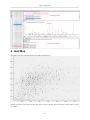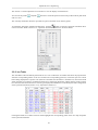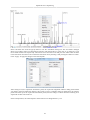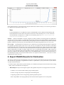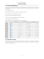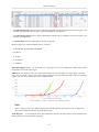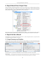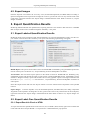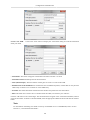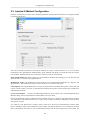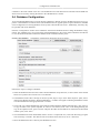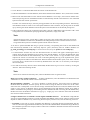
1
PEAKS 6 User Manual
PEAKS Team
PEAKS 6 User Manual
PEAKS Team
Publication date 2012
Table of Contents
1. Overview ................................................................................................................................. 1
1. How to Use This Manual ................................................................................................... 1
2. What Is PEAKS? .............................................................................................................. 1
3. What Is New in PEAKS 6 .................................................................................................. 2
4. Quick Walkthrough ........................................................................................................... 4
4.1. Open an Existing Project .......................................................................................... 4
4.2. PEAKS Main GUI .................................................................................................. 5
4.3. Result Summary and Filtration .................................................................................. 6
4.4. Result Visualization ................................................................................................ 7
4.5. Creating a PEAKS Project ........................................................................................ 8
4.6. Conduct an Identification Analysis ............................................................................. 9
2. Installation and Activation ......................................................................................................... 12
1. Package Contents ............................................................................................................ 12
2. System Requirements ....................................................................................................... 12
3. Installation on a Windows Computer ................................................................................... 12
4. Activation ...................................................................................................................... 13
4.1. Activate PEAKS with a trial or purchased license key .................................................. 14
4.2. Register to get a free 30-day trial license key ............................................................. 14
4.3. Use PEAKS as a viewer ......................................................................................... 15
4.4. Activate PEAKS manually ...................................................................................... 15
4.5. Re-registering PEAKS ........................................................................................... 17
4.6. Common Errors during Registration ......................................................................... 18
5. PEAKS Performance Configuration .................................................................................... 18
6. What's Next .................................................................................................................... 19
3. Configuration Wizard - Configure Instruments and Public Databases ................................................. 20
1. Overview ....................................................................................................................... 20
2. Instrument Selection ......................................................................................................... 20
3. Database Selection ........................................................................................................... 21
4. Download Information ...................................................................................................... 22
5. Commit the Changes ........................................................................................................ 23
4. Loading Data to a PEAKS Project .............................................................................................. 25
1. Overview ....................................................................................................................... 25
2. Supported Data Formats ................................................................................................... 26
3. Vendor Specific Requirements ........................................................................................... 26
3.1. Thermo Data ........................................................................................................ 27
3.2. Waters/Micromass (MassLynx) Data ........................................................................ 27
3.3. Agilent Data ......................................................................................................... 27
3.4. Applied Biosystems/Sciex Data ............................................................................... 28
3.4.1. QSTAR or QTRAP ..................................................................................... 28
3.4.2. Convertors for WIFF ................................................................................... 28
3.4.3. ABI 4700/4800 .......................................................................................... 29
3.5. Bruker Data ......................................................................................................... 30
3.6. Shimadzu Data ..................................................................................................... 30
3.7. Varian ................................................................................................................. 31
3.8. PEAKS 5.3 Projects .............................................................................................. 31
4. Creating a New Project ..................................................................................................... 32
5. Adding Data to an Existing Project ..................................................................................... 33
6. Changing the Default Project Location ................................................................................ 33
5. Data Visualization ................................................................................................................... 35
1. Overview ....................................................................................................................... 35
2. MS View ....................................................................................................................... 35
3. MS/MS View .................................................................................................................. 36
4. Heat Map ....................................................................................................................... 37
4.1. Blur / Unblur Heat Map ......................................................................................... 38
4.2. Highlight Feature / Hide Feature .............................................................................. 38
iii
PEAKS 6 User Manual
4.3. Mark Feature / Unmark Feature ...............................................................................
4.4. Show MS2 / Hide MS2 ..........................................................................................
4.5. Show PID ............................................................................................................
4.6. Noise Level ..........................................................................................................
6. Adding a Sequence Database .....................................................................................................
1. Configuring Sequence Databases ........................................................................................
2. Databases to be Used in PEAKS' inChorus Function ..............................................................
7. Data Refinement ......................................................................................................................
1. Overview .......................................................................................................................
2. Data Refinement Parameters ..............................................................................................
2.1. Saving the Parameters for Future Use .......................................................................
8. Peptide De Novo Sequencing .....................................................................................................
1. Overview .......................................................................................................................
2. De Novo Sequencing Parameters ........................................................................................
2.1. Error Tolerance .....................................................................................................
2.2. Enzyme Specificity ................................................................................................
2.3. Fixed and Variable PTMs .......................................................................................
2.4. Other Parameters ...................................................................................................
2.5. Saving the Parameters for Future Use .......................................................................
3. Understanding PEAKS De Novo Sequencing Results .............................................................
3.1. Summary View .....................................................................................................
3.2. De Novo Peptide View ...........................................................................................
3.2.1. Peptide Table .............................................................................................
3.2.2. Spectrum Annotation ...................................................................................
3.2.3. Ion Table ..................................................................................................
3.2.4. Error Map .................................................................................................
3.2.5. Spectrum Alignment ....................................................................................
3.2.6. Parent Scan ...............................................................................................
4. Filtering De Novo Sequencing Results .................................................................................
5. Export De Novo Results ...................................................................................................
6. Run Auto De Novo Sequencing on a Single Spectrum ............................................................
7. Manual De Novo Sequencing .............................................................................................
7.1. Manual De Novo Graphical User Interface .................................................................
7.2. Manual De Novo Operations ...................................................................................
9. Peptide, PTM and Mutation Identification (PEAKS DB, PEAKS PTM, SPIDER) ................................
1. Overview .......................................................................................................................
2. Set PEAKS Parameters .....................................................................................................
3. Understanding PEAKS Database Search Result .....................................................................
3.1. The Peptide and Protein Scores ...............................................................................
3.2. Summary View .....................................................................................................
3.3. Protein View ........................................................................................................
3.3.1. Protein Table .............................................................................................
3.3.2. Coverage Tab .............................................................................................
3.3.3. Peptides Tab ..............................................................................................
3.3.4. De novo Tags Tab ......................................................................................
3.4. Peptide View ........................................................................................................
3.4.1. Peptide Table .............................................................................................
3.4.2. Peptide Spectrum Match ..............................................................................
3.5. De Novo Only View ..............................................................................................
4. Filter PEAKS Result ........................................................................................................
5. Export PEAKS Results for Publication ................................................................................
6. Running PEAKS PTM and SPIDER Separately .....................................................................
6.1. Run PEAKS PTM on PEAKS DB Result ..................................................................
6.2. Run SPIDER on PEAKS DB or PEAKS PTM Result ..................................................
7. Comparison of PEAKS Results ..........................................................................................
7.1. Comparison Result ................................................................................................
7.2. Peptide Comparison ...............................................................................................
7.3. Protein Comparison ...............................................................................................
iv
39
40
40
41
43
43
44
46
46
46
48
49
49
50
50
51
51
53
53
53
53
54
55
56
58
59
59
59
59
60
60
60
60
62
68
68
69
72
72
72
76
77
77
81
81
82
82
83
84
84
85
86
86
87
88
88
89
90
PEAKS 6 User Manual
10.
11.
12.
13.
14.
15.
7.4. Statistical Charts ................................................................................................... 90
7.5. Exporting Comparison Results ................................................................................. 91
PEAKS InChorus ................................................................................................................... 92
1. PEAKS inChorus Overview ............................................................................................... 92
2. Understanding PEAKS inChorus Result ............................................................................... 94
3. Filtering PEAKS inChorus Result ....................................................................................... 96
4. Exporting inChorus Result ................................................................................................ 97
PEAKS Q - MS Level ............................................................................................................ 98
1. Overview ....................................................................................................................... 98
2. Setting Parameters ........................................................................................................... 98
3. Understanding the Result .................................................................................................. 99
3.1. Summary View ................................................................................................... 100
3.2. Protein View ...................................................................................................... 100
3.3. Peptide View ...................................................................................................... 101
3.4. Filtering Quantification Result ............................................................................... 101
4. Export Quantification Results ........................................................................................... 101
PEAKS Q - MS/MS Level ..................................................................................................... 102
1. Overview ...................................................................................................................... 102
2. Setting Parameters .......................................................................................................... 102
3. Understanding the Result ................................................................................................. 103
3.1. Summary View ................................................................................................... 103
3.2. Protein View ...................................................................................................... 104
3.3. Peptide View ...................................................................................................... 105
3.4. Filtering Quantification Result ............................................................................... 105
4. Export Quantification Results ........................................................................................... 106
PEAKS Q - Label Free ......................................................................................................... 107
1. Overview ...................................................................................................................... 107
2. Setting Parameters .......................................................................................................... 107
3. Understanding the LFQ Result ......................................................................................... 109
3.1. Summary View ................................................................................................... 109
3.2. Protein View ...................................................................................................... 110
3.2.1. Extracted Ion Chromatogram ....................................................................... 111
3.2.2. Heat Map ................................................................................................ 111
3.2.3. MS2 Annotation ....................................................................................... 112
3.2.4. Isotope .................................................................................................... 112
4. Filter LFQ Result ........................................................................................................... 113
5. Export Quantification Result ............................................................................................ 113
6. Replicate Analysis in LFQ ............................................................................................... 113
6.1. Assign Replicate Number to a Sample ..................................................................... 113
6.2. Run Replicate Analysis ........................................................................................ 115
6.3. Understand the Replicate Analysis Results ............................................................... 116
6.4. Export Replicate Analysis Result ............................................................................ 118
Workflow ........................................................................................................................... 119
1. Identification Workflow .................................................................................................. 119
2. Quantification Workflow ................................................................................................. 120
3. inChorus Workflow ........................................................................................................ 121
Exporting Data/Reports and Printing ........................................................................................ 122
1. Export Data .................................................................................................................. 122
2. Export Result From Project View ..................................................................................... 123
3. Export De Novo Result ................................................................................................... 123
3.1. Export Summary and Peptides ............................................................................... 123
3.2. Export Images ..................................................................................................... 124
4. Export Database Search Result ......................................................................................... 125
4.1. Export Summary, Proteins and Peptides ................................................................... 125
4.2. Export Images ..................................................................................................... 127
5. Export Quantification Results ........................................................................................... 127
5.1. Export Labeled Quantification Results ..................................................................... 127
5.2. Export Label-Free Quantification Results ................................................................. 127
v
PEAKS 6 User Manual
5.2.1. Export Result in Excel or HTML .................................................................
5.2.2. Export Summary and Detected Features ........................................................
6. Export inChorus Result ...................................................................................................
16. Configuration and Preferences ................................................................................................
1. PEAKS Environment Preferences .....................................................................................
1.1. General Preferences .............................................................................................
1.1.1. Display Options ........................................................................................
1.1.2. RMI Connections ......................................................................................
1.1.3. Derby Database ........................................................................................
1.2. Raw File Converter Preferences .............................................................................
1.2.1. ABI (.wiff) ..............................................................................................
1.2.2. Bruker (.yep/baf, fid) .................................................................................
1.2.3. Shimadzu AXIMA (.run) ............................................................................
1.2.4. Varian (.xms) ...........................................................................................
1.2.5. Waters (.raw) ...........................................................................................
1.3. Search Engine Preferences ....................................................................................
1.3.1. Mascot Settings ........................................................................................
1.3.2. X!Tandem Settings ....................................................................................
1.3.3. OMSSA Settings .......................................................................................
1.4. Spectrum Annotation Preferences ...........................................................................
2. PEAKS Configuration .....................................................................................................
2.1. Enzyme Configuration ..........................................................................................
2.2. PTM Configuration ..............................................................................................
2.3. Labeled Q Method Configuration ...........................................................................
2.4. Database Configuration .........................................................................................
2.5. Instrument Configuration ......................................................................................
vi
127
128
129
130
130
130
131
131
131
132
132
132
132
132
133
133
133
133
134
134
135
135
136
139
140
142
Chapter 1. Overview
Welcome to PEAKS.
1. How to Use This Manual
This chapter of the manual provides an overview of PEAKS' distinctive features and describes a typical data analysis workflow in PEAKS. Users are strongly recommended to read this chapter to get a big picture of what PEAKS
provides and how PEAKS is used. Other parts of this manual are intended for reference and do not need to be read
from cover to cover. Many contents of this manual can be read from the software's inline help. An electronic (and
most up-to-date) version of this manual can be found at http://bioinfor.com/doc/peaks6/htmlmanual/index.html.
The installation of the software is covered in a separate chapter, Chapter 2, Installation and Activation.
2. What Is PEAKS?
PEAKS is a complete software package for proteomics mass spectrometry data analysis. Starting from the raw
mass spectrometry data, PEAKS takes care of every step of data conversion; peptide and protein identification;
PTM and mutation characterization; as well as result validation, visualization and reporting.
1
Overview
The following is a partial list of the distinctive features of PEAKS software:
• Complete Analysis
PEAKS combines four complementary algorithms for de novo sequencing, database search, characterizing unspecific PTMs, and detection of peptide mutations. The combined use of the four algorithms maximizes the
number of identifications.
• Built-in Result Validation
A decoy fusion method is used to validate the peptide identifications automatically. The decoy fusion method
is an enhanced result validation method that avoids several pitfalls existing in the commonly used target-decoy
method. With an informative result summary view, the results can be easily filtered by false discovery rate
(FDR).
• Protein Coverage View
All the identified peptides are mapped to the identified proteins and displayed in a consolidated protein coverage view. All the PTMs and mutations on the protein sequence are highlighted. The interactive graphical user
interface (GUI) allows the in-depth and effortless examination of every amino acid in the identification results
and every peak in the data.
• Accuracy and Sensitivity
The superiority of each identification algorithm used by PEAKS has been demonstrated by publications and/
or third-party evaluations. By combining four complementary algorithms together, the sensitivity is further
improved.
• Multiple-enzyme Project
To maximize a protein's sequence coverage, it is advantageous to use different proteolysis enzymes to digest
the protein sample. PEAKS supports the use of different enzymes in different samples of a single project. The
software will automatically use the enzyme specified in each sample, and combine all samples' results together.
• Multiple Instrument Vendor Support
PEAKS supports most major instruments' raw file formats, which saves the trouble for file format conversion
by the users. More importantly, the algorithms' parameters are optimized for each different instrument type,
respectively, to ensure the accuracy and sensitivity.
• Result Exporting
The analysis result can be exported to a variety of text files. The website format makes it easy to share the
results on a website as html pages; whereas other text formats such as .csv make it easy to post-analyze the
results with Excel or users' in-house software. Additionally, PEAKS can export to standard result formats such
as pepxml and mzIdentML.
• inChorus
If your lab already acquired other database search engines, PEAKS can import the other engines' results and
combine all the results together. The inChorus function supports the result filtering of all engines' results with
a unique FDR. For each identified peptide, PEAKS also displays all the engines that identified the peptide, as
well as each engine's identification score.
3. What Is New in PEAKS 6
Here is a list of the noteworthy new features in PEAKS 6.
Highlights.
2
Overview
• Interactive protein coverage view
In this beautiful graphical display, all peptides identified for a protein are mapped to the protein sequence. The
PTMs and mutations are highlighted. Individual peptide-spectrum matches can be examined with simple mouse
clicks.
• Easy workflow for complete analysis
With a single mouse click, the PEAKS PTM (blind search for PTMs) or the SPIDER (mutation detection)
algorithm can be included in the analysis workflow.
• Multiple enzyme support
One project can include multiple samples, each with a different proteolysis enzyme. The overlapping peptides
from different enzyme digests maximize the protein coverage.
• Blind search of PTMs
Users can turn on all of the more than 600 variable PTMs in the Unimod database, and let the software find
what PTMs are present.
Algorithm Improvements.
• New nonspecific enzyme digestion support
Now one can allow nonspecific enzyme digestion at 0, 1, or both ends of a peptide. Having more nonspecific
digestion ends will increase the search sensitivity at a reduced search speed.
• Neutral loss of phosphorylation and sulfation PTMs are considered in the scoring functions of PEAKS DB and
PEAKS PTM
• New support for protein N-term PTMs
• New -10lgP score and FDR control for PTM and SPIDER results.
• FDR control of the inChorus result
Different search engines results can now be combined according to a unified FDR for each search engine.
• Improved precursor mass correction
The mass correction function in the "data refine" step recognizes the real monoisotopic mass even if the
instrument's raw data reported the isotope mass. The algorithm is improved in the new version.
GUI Improvements.
• Easier PTM selection interface
The PTMs are separated in three "common", "uncommon", "customized" to make it easy to specify the PTMs
to search for. Additionally, a "Recent" list includes all the PTMs recently used by the user.
• De novo only view added to the inChorus result
The de novo only view reports peptides found exclusively by de novo sequencing. This useful view is now
available to the inChorus result too.
• Improved spectrum annotation view
Mouse over an amino acid in the spectrum annotation will highlight the supporting fragment ions. Setting an
anchor peak will show the mass different between the current peak and the anchor peak.
3
Overview
• Improved project creation interface
The selection of instrument type and fragmentation mode is easier. Users can specify a proteolysis enzyme for
each sample at the project creation interface.
• More searching functions to locate a specific de novo sequence result.
Now de novo sequencing results can be sorted and searched with the amino acid sequence.
• Display absolute intensity in PEAKS Q
Users now can choose to display absolute intensities or ratios in PEAKS Q results. For the ratio display, users
can choose which sample the ratio is based on.
• More statistics in the summary view
The PTM profile table is improved. A protein FDR value is added.
• One-click specification of common FDR values (e.g. 1%) in the FDR selection pane.
Better Community Support.
• A new configuration wizard to assist the download and installation of public protein databases and raw file
readers/convertors.
• Major accuracy and sensitivity improvement on the analysis of AB SCIEX TripleTOF data.
• Proteome Discover support
Now PEAKS can load the pepXML result file generated from Thermo's Proteome Discover software.
• Support mzIdentML result format
Now PEAKS can export mzIdentML file for downstream analysis such as Scaffold PTM.
• Export high resolution images of the spectrum annotation and protein coverage view.
• Export to website or single webpage format for easy sharing of results.
4. Quick Walkthrough
In this section we present a quick walkthrough of a typical data analysis and result visualization process. By using
the sample project included in PEAKS installation, we first introduce the main GUI of PEAKS and showcase how
to filter and visualize the analysis result (Sections 4.1 - 4.4). This will help understand what can be accomplished
with PEAKS. After that we demonstrate how to create a PEAKS project from raw data and conduct data analysis
(Sections 4.5 - 4.6).
4.1. Open an Existing Project
The installation of PEAKS can be found at Chapter 2, Installation and Activation. After installation and running
PEAKS, you can open the sample project by one of the following two ways (see screenshot below):
1. If this is a fresh installation, click the "Sample Project" in the "Recent Projects" list of the Start Page.
2. Click the open project button, and browse to the directory where PEAKS6 was installed, select "SampleProject"
and click the open button in the file browser.
4
Overview
4.2. PEAKS Main GUI
The main graphical user interface (GUI) of PEAKS is divided into several areas (see screenshot below):
1. The project tree shows all the opened projects. Each project may include multiple samples and each sample
may include multiple fractions (LC-MS runs). The analysis results are also displayed as result nodes under
the project.
2. The menu and toolbar. Selecting a node (project, sample, fraction, or result) in an opened project will highlight
the common analysis tool icons available to the selected node.
3. A result node in a project can be opened by double clicking the node. All opened result nodes are shown here
as different tabs.
4. Each opened result node provides several different "views" as different tabs. In particular, the summary view
shows the result statistics. The summary view is also the central place to filter and export the results.
5. The information pane shows useful information such as the node properties and the progress of running tasks.
5
Overview
4.3. Result Summary and Filtration
After opening a result node by double clicking it, i.e. the "SPIDER" node in the sample project, the default view
of the opened result node is the summary view. The summary view provides mainly three functions:
1. Specify score thresholds to filter the results.
2. Examine the result statistics.
3. Export results.
The top region of the summary view is a control pane and the bottom region is a statistics report page. The result
filtration is controlled at the top control pane (see screenshot below):
• The peptide identification is filtered by the peptide-spectrum match's -10lgP score. Or, one can simply specify
the desired FDR (false-discovery rate) by clicking the FDR button.
• The protein identification is filtered by the protein's -10lgP score and the number of unique peptides the protein
contains.
• The de novo only peptides are those with confident de novo sequence tags but cannot be identified by other
algorithms used for database search. To report a de novo only peptide, the TLC (total local confidence) and
ALC (average local confidence) scores must be better than or equal to the specified threshold. Meanwhile, the
spectrum's best database search result's score should be no greater than the specified -10lgP threshold.
TLC measures the approximate number of correct amino acids in the de novo sequence, and ALC measures the
approximate percentage of correct amino acids in the de novo sequence.
By default, the -10logP threshold used for de novo only is locked to be the same as the -10lgP threshold used
for filtering peptides. To specify a different value, first click the lock icon to unlock it.
After the filtration criteria are changed, the "Apply Filters" will change to red. Click it to apply the new criteria.
6
Overview
The top control pane has two additional buttons: "Export" and "Notes". The result can be exported by clicking
the "Export" button. The Notes button allows you to type in a text note about the project, which will be displayed
in the result summary report.
After applying filters, the statistics report page at the bottom of the summary view will be updated accordingly.
We only explain two statistical charts here (see screenshot below).
Figure 2 (a) shows the PSM score distribution. If the search result and the peptide -10lgP score threshold is of high
confidence, then you should observe very few decoy matches (brown) in the high score region. Additionally, if
the FDR estimation method (decoy fusion) worked properly, then you should observe a similar or larger number
of decoy (brown) matches than target (blue) matches in the low score region.
Figure 2 (b) plots the precursor mass error v.s. score for all the PSMs above the -10lgP score threshold. This
figure is the most useful for high resolution instruments. Generally you should see that the high-scoring points
are centered around the mass error 0. And only below a certain score threshold the data points start to scatter to
have bigger mass error.
4.4. Result Visualization
Besides the summary view, there are three other views, "protein", "peptide", and "de novo only", for visualizing
the results in different ways:
• The protein view contains a list of proteins passing the filtration. The proteins identified with the same set (or
a subset ) of peptides are grouped together.
• The peptide shows all the peptide identifications passing the filtration. The multiple spectra that identified the
same peptide sequence are grouped together.
• The de novo only view shows all the peptides identified exclusively by de novo sequencing.
Here we only focus our attention on the new protein coverage view in PEAKS 6. Click the protein view tab,
and select one protein. The following protein coverage will show at the bottom of the protein view. The protein
coverage view maps all peptide identifications of the selected protein onto the protein sequence. It enables the
effortless examination of every PTM and mutation on each amino acid. Some most commonly used operations on
this protein coverage view are listed in the following (see screenshot below):
1. Each blue bar indicates an identified peptide sequence. A gray bar indicates a de novo only tag match.
Peptide identifications with the same amino acid sequence and the same "interesting" PTMs are grouped together and displayed as a single bar. A PTM is "interesting" if it's checked in the display option (see item 5).
7
Overview
2. PTMs and mutations are highlighted with colored icons and white letter boxes. Highly confident PTM and
mutations are displayed on top of the protein sequence.
A PTM or mutation is regarded as confident if the two fragment ions at both sides of the modified residue have
relative intensity higher than the user-specified threshold in the display option (see item 5).
3. Click a peptide to show the spectrum annotation.
4. Mouse over an amino acid to show the supporting fragment ion peaks.
5. Options to control the coverage view display.
• The "coverage/outline" choice turns on/off the peptide bars.
• The "de novo only tag" specifies the minimum number of consecutive amino acid matches between a de
novo only sequence and the protein before it can be displayed as the gray bar.
• The "confident PTM" specifies the minimum fragment ion relative intensity in one of the MS/MS spectra
before a PTM location is regarded as confident, and displayed on top of the protein sequence.
• The checkboxes in the PTM list specifies which PTMs are "interesting". Click the color boxes to change a
color. Double click a PTM name to see the PTM detail.
6. The full screen button and tool box button.
Full screen provides a larger view of the coverage. The tool box provides some common tools, such as exporting
the coverage pane as a high-resolution image file.
4.5. Creating a PEAKS Project
To create a new PEAKS project from raw data files, follow the following steps (see screenshot below):
1. Click the new project button at the tool bar.
2. Click the "Add sample" and "Add data file" buttons to add samples to the project and data files to each sample.
8
Overview
3. For each sample, specify the sample details.
In particular, each sample can use a different proteolysis enzyme. Using multiple enzymes to analyze the same
proteins can produce overlapping peptides and therefore increase the protein coverage.
4.6. Conduct an Identification Analysis
To conduct an identification analysis: 1) select a project, sample, or result node from the project tree. 2) Click the
desired analysis tool button. Here we show the PEAKS complete identification analysis workflow.
9
Overview
A search parameter pane will pop up. Most search options are standard and straightforward. More details are
provided in the following (see screenshot below):
1. If the proteolysis enzyme was specified for each sample at the project creation step, one can choose to use
the enzyme specified in each sample. This makes it possible to use multiple enzymes in a single project and
a single search.
2. Specify the fixed PTMs and a few common variable PTMs expected in the sample.
3. Select a protein sequence database, or copy and paste the protein sequences for the database search.
4. Conduct de novo sequencing using the same parameters, or base the search on an existing de novo sequencing
result node.
5. Estimate the false discovery rate (FDR) with the decoy fusion method.
Decoy fusion is an enhanced target-decoy method for result validation with FDR. Decoy fusion appends
a decoy sequence to each protein as the "negative control" for the search. See BSI's web tutorial (http://
www.bioinfor.com/peaks/tutorials/fdr.html) for more details.
6. Including PEAKS PTM and SPIDER algorithms for the search.
By default, PEAKS PTM performs a blind search for additional PTMs in the data. Users can also limit the
PEAKS PTM search on a large number of PTMs by clicking the "Advanced Setting" button.
SPIDER performs homology search based on de novo sequencing tags. If selected, the SPIDER algorithm will
be conducted on every confident de novo tag (ALC>30%) whose spectrum is not identified by PEAKS DB
with high confidence (-10lgP<30). SPIDER will construct new peptide sequences by altering amino acids of
database peptides. For each spectrum, the better sequence constructed by SPIDER or found by PEAKS DB will
be used as the identified peptide. SPIDER is good for cross-species searches and for finding point mutations
of the protein. It makes no difference to invoke SPIDER through this workflow or by clicking the SPIDER
icon in the toolbar.
10
Overview
11
Chapter 2. Installation and Activation
This section of the manual will guide users through the installation and registration of PEAKS.
1. Package Contents
The PEAKS package contains:
• This manual
• PEAKS Software
• Quick reference guide for PEAKS
• Quick reference sheet for mass spectrometry
2. System Requirements
PEAKS runs and has been tested on Windows XP, Vista, and 7. The computer on which PEAKS is installed should
meet the following hardware requirements:
Minimum: A dual core processor, 2GB RAM and 100GB free hard drive space (this suggestion is mainly for
viewing purposes only; for data analysis we strongly suggest following the recommended requirements below).
Recommended: A quad core processor, 8GB RAM, 500GB free hard drive space and 64-bit OS.
3. Installation on a Windows Computer
Important
Please uninstall any older version of PEAKS currently installed on the system before proceeding.
Important
Avoid installing PEAKS in any directory that contains a white space, for example the Program Files
directory as some features may not function correctly in such situations. Please make sure that the user
account has full access permissions (read/write/execute) on the selected directory.
Important
To open an instrument's raw data using PEAKS, it is necessary to install PEAKS on the same computer
where the instrument vendors' own software is installed. Refer to Section 3, “Vendor Specific Requirements” for the vendor-specific requirements for raw data loading.
1. Close all programs that are currently running.
2. Insert the PEAKS disc into the CD-ROM drive. Or double click on the downloaded PEAKS installation file
and move ahead to step 4.
3. The installation window should automatically appear after the CD-ROM is inserted. If it does not, find the CDROM drive and open it to access the disc. Double-click on PEAKS_Studio_Installation.exe.
4. A menu screen will appear. Select the top item “PEAKS Installer”. The installation utility will launch the
installer. When the PEAKS installation dialogue appears, click the “Next” button.
12
Installation and Activation
5. Follow the on-screen instructions to finish the installation.
4. Activation
All users are required to go through a software activation process in order to use PEAKS. A license wizard will
appear to guide the activation process the first time PEAKS is launched.
13
Installation and Activation
Important
Keep your license key safe. After a computer hardware upgrade, it might be required to re-activate the
software.
4.1. Activate PEAKS with a trial or purchased license key
The software activation process is very simple. If your computer connects to the internet, you can activate PEAKS
by clicking on the first option in the wizard. In the 'Enter the License Key' dialog, paste or type in the license
key and click 'Activate' button. If the activation is successful, PEAKS will then start. In the situations where the
activation failed with the message 'An error occurred while communicating with BSI licensing server ...', refer to
Section 4.4, “Activate PEAKS manually”.
4.2. Register to get a free 30-day trial license key
This option allows new PEAKS users to evaluate the software before purchase. If the computer is connected to
the internet, clicking on this option will bring up a web form in the default web browser. Please provide your
full name, institution, email address and phone number in the form. After the form is submitted by clicking the
14
Installation and Activation
'Register' button, an email from [email protected] will be sent to you with the trial license key. This key can
then be used to fully activate PEAKS for evaluation purposes.
Important
Each computer can only have one free trial. Request trial license repetitively will not extend your trial
automatically. Please contact [email protected] to discuss a trial license extension.
4.3. Use PEAKS as a viewer
BSI has consolidated the PEAKS product line. PEAKS Studio and Viewer are now one product. Unlicensed
PEAKS Studio can be used in viewer mode. Researchers around the world are now able to take advantage of
PEAKS most advanced user interface to share PEAKS results. In the viewer mode, all non-analytical features,
such as read/display raw data, open/navigate through existing PEAKS results, exporting etc, work the same way
as the full PEAKS Studio version.
4.4. Activate PEAKS manually
In certain situations, when the computer does not have an Internet connection (or is behind a firewall that blocks
the activation), the activation process requires the assistance of another computer with an Internet connection (or
outside the firewall). Manual activation can be accessed via the link on the bottom-right corner of the wizard.
Manual activation consists of the following steps.
1. Provide the license key and user information required to the license wizard on the computer that will be running
PEAKS.
2. Save a generated request file to a removable storage device (e.g. a USB memory key).
15
Installation and Activation
3. From another computer with an Internet connection, upload the license request file to BSI's license server as
described in the following screen.
16
Installation and Activation
4. If the license request is sent successfully, an automated BSI service will generate the license file (license.lcs)
and send an email (from <[email protected]>) to the email address provided to the License Wizard.
Either save the attached license file or copy the content between '===>' and '<===' in the email to the Windows
clipboard.
5. Transfer the license file to the computer running PEAKS, and import the license file into the license wizard.
4.5. Re-registering PEAKS
Re-registering PEAKS may be necessary when an additional software module was purchased or SPS was renewed.
BSI will modify the license information accordingly on the server side. A new license file is required to make
the changes effective. Select “About PEAKS” from the Help menu. The “About BSI PEAKS Studio” dialogue
box will appear:
17
Installation and Activation
Click the “License Wizard” button to continue. Then follow the instructions in Section 4.1, “Activate PEAKS with
a trial or purchased license key” or Section 4.4, “Activate PEAKS manually” for re-registering PEAKS.
4.6. Common Errors during Registration
1. The license key contains only English letters and numbers. It is recommended to copy (ctrl-C) / paste (ctrl-V)
the license key whenever possible.
2. The user information can only contain English characters (letters, digits and symbols). Characters from a nonEnglish encoding may cause the activation to fail.
3. If the computer is behind a firewall or has other internet connection problems, the activation may fail. Please
follow the on screen instructions or refer to Section 4.4, “Activate PEAKS manually”.
5. PEAKS Performance Configuration
The PEAKS Performance Configuration tool can be accessed from the Windows Start Menu. By default, PEAKS
automatically determines its performance parameters, to take full advantage of the processors and memory available on the computer. In most situations, the 'Automatically Configure PEAKS Performance' option should be
used. For advanced users, the 'Manually Configure PEAKS Performance' option will come in handy in situations
where users want to start PEAKS using different JVMs, or to change the size of JVM heap to their preferred
configuration.
18
Installation and Activation
1. Main Program JVM Heap Size (MB). This is the amount of memory assigned to the main PEAKS program. In
some computers, more often on 32 bit systems, if PEAKS fails to start, lower this number, e.g. 800, may help.
2. Number of Computing Nodes to Start. This option determines the number of concurrent processes PEAKS
will use. One PEAKS license will allow up to four computing nodes to be used. The more nodes started the
more memory PEAKS requires. It is important not to start more nodes than the computer can handle. On 32
bit systems, this number should always be set to one. On 64 bit systems, a safe estimation on the number of
nodes can be calculated as: min(4,[RAM in GB]/2). For example, on the Windows 7 64 bit computer with 6GB
RAM, the maximum number of nodes that can be used is min(4,6/2) = 3.
3. Start Client Separately. This option provides the raw file reading abilities of a 32 bit JRE and the processing
power of 64 bit system together. Use the 'Browse' button to point to the 'bin' directory of an installed 32 bit Java
Runtime. Specify the 'Client JVM Heap Size (MB)' to assign memory to PEAKS Client components. Usually
1024 works fine.
4. Start Compute Node Separately. This option should be used on 64 bit systems when the 'Number of Computing
Nodes to Start' is greater than 1. Use the 'Browse' button to point to the 'bin' directory of an installed 64 bit
Java Runtime. Specify the 'Computing Node JVM Heap Size (MB)' to assign memory to each node. Usually
a number greater than 1500 should be used.
Important
The total amount of memory used by all the nodes computing nodes are 'Computing Node JVM Heap
Size (MB)' multiplied by the 'Number of Computing Nodes to Start'.
6. What's Next
You are almost done. Depending on the data formats and the type of analysis needed, there may still be two
additional configuration steps before data analysis can be conducted.
• To read the instrument's raw data formats, it might be required to install specific software libraries to support
the instrument. See Section 3, “Vendor Specific Requirements” for this requirement.
• To conduct database search for protein identification, a protein (or EST) sequence database must be configured.
See Chapter 6, Adding a Sequence Database.
If you are eager to try PEAKS now, leave these two configuration steps aside for a while, and try out the 15-minute
walkthrough to get familiar with PEAKS' GUI and basic operations. See Section 4, “Quick Walkthrough”.
19
Chapter 3. Configuration Wizard Configure Instruments and Public
Databases
1. Overview
The configuration wizard guides you through some easy to follow steps to configure PEAKS for instrument raw
data support and database searching. The configuration wizard can also be invoked from the menu: Window -> Config Wizard.
PEAKS supports different instrument vendors' raw data formats. A list of supported formats can be found in
Section 2, “Supported Data Formats”. Some vendors' formats may require the vendors' specific software to be
installed on the same computer that PEAKS is running on. The configuration wizard helps you to select the proper
instrument and install the appropriate vendor software.
A sequence database must be configured in PEAKS to identify peptides and proteins with the MS/MS spectra by
database searching. The configuration wizard helps you to select the appropriate database from a list of standard
sequence databases, download and configure them automatically. The list of standard databases can be found in
Section 3, “Database Selection”.
2. Instrument Selection
When you select "Window --> Config Wizard", the configuration wizard will run and display a welcome message.
Clicking the“Next” button shows the following instrument selection panel.
20
Configuration Wizard - Configure
Instruments and Public Databases
The instrument selection panel lists all the supporting instruments and their vendor specific softwares. Select the
instruments as necessary. A small description about the instrument is displayed once it is selected. Click “Next”
to proceed.
3. Database Selection
The database selection panel lists the standard databases. The automatically downloadable databases are NCBI nr,
SwissProt, TrEMBL, and IPI human. Select the databases to be configured. A small description of the database is
displayed once selected. If a standard database is already configured using this wizard then “[configured]” text in
green will appear beside its name in the list. It can be selected again to overwrite the configuration.
21
Configuration Wizard - Configure
Instruments and Public Databases
The “Database Path” displays the location where the configured database will be stored. Click the “Browse” button
to change the default database path. Click “Back” to go back to the instrument selection panel. Click “Next” to
proceed to the download information panel.
4. Download Information
The download information panel displays all the requested instrument software and database downloads in two
tables - “Downloads” and “Selected Instrument Software”.
22
Configuration Wizard - Configure
Instruments and Public Databases
Downloads - The “Downloads” table shows all the downloadable requests, their status and available actions on
them. The status of an ongoing download is displayed in the “Progress” column. To cancel an ongoing download,
click the “Cancel” button in the “Action” column. Once completely downloaded, the “Install” button appears in the
“Action” column. The corresponding software can be installed or the corresponding database can be configured
by clicking the “Install” button. The “Next” button remains disabled until all the downloads and the installations
are completed. An already installed item can be reinstalled by clicking the “Reinstall” button that appears in the
“Action” column once the corresponding item is installed.
Selected Instrument Software - The configuration wizard cannot download some vendor specific software as the
corresponding vendor needs to be contacted to get that software. If any of those software packages were selected in
the instrument selection panel then their information appears in the “Selected Instrument Software” table. Clicking
the “Display Information” button shows information on how to get the software from the vendor in a popup dialog.
Click “Back” to go back to instrument selection or the database selection panel to change the selection. Click
“Cancel” to cancel the wizard anytime. All ongoing downloads will be cancelled if the wizard is cancelled. Click
“Next” to finalize the configuration. A warning message box will pop up in case any downloaded item is not
installed.
5. Commit the Changes
After configuring the necessary downloaded vendor specific software and standard databases, click the “Next”
button to get to finalize the panel.
23
Configuration Wizard - Configure
Instruments and Public Databases
A summary about the changes that the wizard is going to make will be displayed. Click the “Finish” button to
commit to the changes to the configuration file. The changes will be immediately available to PEAKS.
24
Chapter 4. Loading Data to a PEAKS
Project
1. Overview
Mass spectrometry data needs to be loaded into a PEAKS project before any analysis can be done. After creation,
a PEAKS project is shown as a project node in the top left corner of the PEAKS user interface. On the computer's
file system, a project is saved as a directory that contains multiple files that contain the compressed spectral data
and the analysis results. It is possible to transfer the whole project directory to another user to open with PEAKS
Studio or the free PEAKS Viewer.
To create a new project simply click the new project button
on the toolbar. The following “New Project”
dialog will appear. This is where new samples and data files (a.k.a. fractions of samples) can be added. Users
also get the chance to specify important properties of the data files, such as the name, replicate number, enzyme,
fragmentation method and instrument type. Clicking the "Copy to whole project" button will let the whole project
share the same settings of enzyme, instrument and fragmentation.
PEAKS supports different instrument vendors' raw data formats. A list of supported formats can be found in
Section 2, “Supported Data Formats”. Some vendors' formats may require the vendors' specific software to be
installed on the same computer that PEAKS is running on. Before creating a project with your own data, ensure
that the vendor-specific requirements discussed in Section 3, “Vendor Specific Requirements” are met.
Upon clicking the OK button in the "New Project" dialog, PEAKS will make an effort to import the vendors' raw
MS data into the PEAKS project. Once the data is loaded it becomes a part of that project so that the original data
files can be manipulated or deleted without affecting the analysis in PEAKS.
25
Loading Data to a PEAKS Project
To close an open project, select the project and choose “Close Project” command from the file menu or use the
close project icon
memory.
from the tool bar. It is recommended to close the unused projects to preserve computer
The rest of this chapter discusses the details of data loading and project creation.
2. Supported Data Formats
The following is a list of supported data formats in PEAKS. PEAKS supports these formats at three different levels:
• Native Support - PEAKS can read the following files directly without any additional tools:
• mzXML
• mzData
• mzML
• .DTA file or a directory of .DTA files
• .MGF
• .PKL
• PEAKS 5.3 projects. See Section 3.8, “PEAKS 5.3 Projects”.
• Library Level Support - The instrument vendor's software library is required to be installed on the same computer
as PEAKS. PEAKS will call the software library to read the data directly.
• .RAW file (Thermo Fisher Scientific instruments). See Section 3.1, “Thermo Data”.
• .D directory (Agilent instruments). See Section 3.3, “Agilent Data”.
• .LIFT or .D directory (Bruker instruments). See Section 3.5, “Bruker Data”.
• .RAW directory (Waters QTOF instruments). See Section 3.2, “Waters/Micromass (MassLynx) Data”.
• Convertor Level Support - Third party convertors are required. Users need to install the required convertors
correctly and let PEAKS know their locations. This only needs to be set up once. PEAKS will call the convertor
to convert the data to another supported format before loading. The actual convertion process is invisible to
the user.
• .RAW directory (Waters QTOF instruments). See Section 3.2, “Waters/Micromass (MassLynx) Data”.
• .WIFF file (AB/Sciex QSTAR and QTRAP instruments). See Section 3.4.1, “QSTAR or QTRAP”.
• .T2D file (AB 4700/4800 series). See Section 3.4.3, “ABI 4700/4800”.
• .RUN folders from Shimadzu instruments. See Section 3.6, “Shimadzu Data”.
• .XMS files from Varian instruments. See Section 3.7, “Varian”.
3. Vendor Specific Requirements
Most vendors provide tools for MS analysis software to read their raw data format. PEAKS works best with raw
data because it is unprocessed. This allows it to use the data pre-processing tools built in to the software designed
to maximize identification results. Listed below are the requirements to load raw data from each supported vendor.
26
Loading Data to a PEAKS Project
3.1. Thermo Data
RAW data from Thermo Fisher Scientific mass spectrometers can be loaded, provided that the XCalibur software
or the Thermo MSFileReader package is installed on the same computer as PEAKS. The PEAKS Config Wizard
can download and install MSFileReader automatically (see Section 2, “Instrument Selection”). MSFileReader is
publicly available and can be found at the following link:
http://sjsupport.thermofinnigan.com/peg/file/MSFileReader.zip
Converting with MSFileReader will only work if there are English only characters in the file path.
3.2. Waters/Micromass (MassLynx) Data
Two ways can be used to load Waters's .raw data.
• Library Level Support -- wolf.exe.
RAW data from Waters instruments can be imported provided that MassLynx 4.1 software is installed on the
same computer as PEAKS. MassLynx 4.0 users, can download a different version of wolf.exe. Command line
can be used to convert raw files to mzXML with wolf.exe. The file [Peaks installation directory]/wolf.exe can
be replaced with the program compatible with MassLynx 4.0. For links to different versions of Wolf visit the
link below:
http://www.bioinfor.com/peaks/support/formats/peaks-watersmicromass-masslynx-data.html
• Converter Level Support - massWolf.exe
Note
If you want to use massWolf in PEAKS, please make sure massWolf is installed correctly and works
from command line on your computer.
If you have massWolf installed on your computer and prefer to use massWolf.exe to convert the .raw data,
define the convertor in preferences. Click the “Preferences” toolbar icon
or select “Preferences” from the
“Window” menu to open the “Preferences” window. Clicking on “Waters(.raw)” under the “Raw file convertor”
section on the menu on the left hand side will show the preferences for massWolf. Point to the location of
massWolf.exe on your computer and enable it.
3.3. Agilent Data
Agilent Q-TOF data can be loaded provided that MassHunter software is installed on the same computer as
PEAKS.
Agilent Ion Trap data can be loaded provided that CompassXtract is installed on the same computer as PEAKS.
The spectral data will be contained in the .yep, .baf, or fid file. If loading fid files, select the top level folder to
load them all at once.
27
Loading Data to a PEAKS Project
CompassXtract 3.1 is readily available on the Bruker Daltonics web site. You may need to contact your Bruker
representative to obtain CompassXtract 3.1.
Instrument Preferences for Bruker Data. This type of Agilent data uses a Bruker converter. To set Bruker data
related preferences in PEAKS, click the “Preferences” toolbar icon
or select “Preferences” from the “Window”
menu to open the “Preferences” window. Click on “Instrument” and then “Bruker (.yep/baf, fid)” in the menu on
the left hand side. This will show the Bruker instrument preferences on the right hand side.
CompassXtract by default will export raw data. If the attempt to load raw data results in no spectra, then choose
“Line spectra”. A Bruker .fid file may contain several samples. By default, these samples are not merged into one
data set. Select “Yes” to merge all the samples into one data set.
3.4. Applied Biosystems/Sciex Data
3.4.1. QSTAR or QTRAP
ABI data can be loaded into PEAKS provided the following converters are installed. Analyst QS is required for
QSTAR data. Analyst 1.4 is required for QTRAP data. AB SCIEX MS Data Converter is required for ABI 5600
data. PEAKS Config Wizard can download and install mzWiff automatically. A link is also provided in the PEAKS
Config Wizard to the AB SCIEX MS Data Converter download site (see Section 2, “Instrument Selection”). Please
see the specified software package to find out the requirements for it.
3.4.2. Convertors for WIFF
Three Wiff convertors are supported by PEAKS. They are 1. AB SCIEX's MS Data Converter. 2. mzWiff and
3. MSX
Note
Before defining the converters in PEAKS, please make sure these software packages are installed correctly and convert successfully from command line on your computer.
To set WIFF related preferences in PEAKS, click the “Preferences” toolbar icon
or select “Preferences” from
the “Window” menu to open the “Preferences” window. Select the “Raw file convertor” section in the menu on
the left hand side then "ABI (.wiff)". This will show the preferences for ABI instruments.
28
Loading Data to a PEAKS Project
Select one of the convertors as the default convertor for WIFF file loading.
AB SCIEX MS Data Converter. Click “Browse” to tell PEAKS the location of the raw file converter. Select
the preferred mode of raw data to load. This is a useful option for ABI 5600 instruments.
mzWiff. Click “Browse” to tell PEAKS the location of the raw file converter. Select “Survey Spectrum Centroiding” if centroiding has been performed before loading the data into PEAKS. Select “Product Spectrum Centroiding” if centroiding has been performed on the product spectrum before loading it into PEAKS. This is important to insure PEAKS performs optimally.
MSX. Click “Browse” to tell PEAKS the location of the raw file converter. Select the preferred options to load
the raw data.
3.4.3. ABI 4700/4800
T2D files can be extracted and imported into PEAKS with a free tool created by BSI. The PEAKS Config Wizard
can download and install the AB 4X00 Extractor automatically (see Section 2, “Instrument Selection”).
System Requirements. This extractor can be installed on the same machine as the ABI 4700 Explorer and
the Oracle database or another machine that has direct network access to the 4700 SERVER. There cannot be a
firewall or proxy between the computers. Windows 7 or Windows XP is recommended for use of this tool.
Configuration. Start the ABI 4700 converter tool. Choose “Settings” from the “File” menu. Configuration
requires the following:
29
Loading Data to a PEAKS Project
• 4700 SERVER Name or IP Address: input “localhost” if the Extractor is running on the same computer as
ABI 4700 Explorer (this is the default value), otherwise enter the IP address of the 4700 SERVER.
• The socket used by the 4700 SERVER: this is the port that the Oracle database listens to (the default is 1521).
• Username to access the Oracle database: most likely we do not need to change this (the default is “tsquared”).
• Password to access the Oracle database: mostly likely you do not need to change this either.
Data Extraction Procedure.
The data extraction requires
1. Load Spot Set List from the database: (Do this via menu File | Load Spot Set List). The extractor will export
the peak list of a spot set into a PKL file.
2. Open a Spot Set: (menu File | Open Spot Set) Spot Set Chooser will help the user to choose a spot set. After
selecting a spot set, click 'OK' to open it. The job run information of a spot set will be shown.
3. Select a job to run: There is a button to select before each run. Only the MS/MS job run can be selected for
export, as the precursor information is needed. Select a job run and click 'Convert' to do the extraction.
4. Choose a filename to save: After clicking the 'Convert' button, the user needs to input a file name and the peak
lists of the selected job run will be exported.
3.5. Bruker Data
.D and .LIFT directories from Bruker mass spectrometers can be imported provided that the CompassXtract Runtime library is installed on the same computer as PEAKS. The spectral data will be contained in the .yep, .baf, or
fid file. If loading fid files, select the top level folder to load them all at once.
CompassXtract 3.1 is readily available on the Bruker Daltonics web site. You may need to contact your Bruker
representative to obtain CompassXtract 3.1.
Instrument Preferences for Bruker Data.
To set Bruker data related preferences in PEAKS, click the “Pref-
erences” toolbar icon
or select “Preferences” from the “Window” menu to open the “Preferences” window.
Click on “Instrument” and then “Bruker (.yep/baf, fid)” in the menu on the left hand side. This will show the
Bruker instrument preferences on the right hand side.
CompassXtract by default will export raw data. If the attempt to load raw data results in no spectra, then choose
“Line spectra”. A Bruker .fid file may contain several samples. By default, these samples are not merged into
one data set. Select “Yes” to merge all the samples into one data set.
3.6. Shimadzu Data
RUN files from Shimadzu mass spectrometers can be loaded provided that the Shimadzu software is installed on
the same computer as PEAKS.
Instrument Preferences for Shimadzu Data.
To set Shimadzu data related preferences in PEAKS, click the
“Preferences” toolbar icon
or select “Preferences” from the “Window” menu to open the “Preferences” window. Click on “Instrument” and then “Shimadzu AXIMA (.run)” in the menu on the left hand side. This will show
the Shimadzu instrument preferences on the right hand side. Click “Browse” to tell PEAKS the location of the
Shimadzu run2xml.exe file.
30
Loading Data to a PEAKS Project
3.7. Varian
A conversion tool is embedded into Varian’s data acquisition software which allows the conversion of Varian raw
data into .pkl files which can be immediately read by PEAKS.
The .trans data files are converted in Varian programs by clicking "File", "Save As" and selecting the .pkl file
format or by clicking "File", right clicking "Export" and selecting ".pkl". If you are viewing a chromatogram with
the Varian software, all the spectral data in the viewed chromatogram is converted to the .pkl format. If you are
viewing a single spectrum and choose to convert the data, only the viewed spectra will be converted.
Importing raw data that has not been preprocessed will produce better results when using the preprocessing options
native to PEAKS.
Instrument Preferences for Varian Data.
To set Varian data related preferences in PEAKS, click the “Pref-
erences” toolbar icon
or select “Preferences” from the “Window” menu to open the “Preferences” window.
Click on “Instrument” and then “Varian (.xms)” in the menu on the left hand side. This will display the Varian
instrument preferences on the right hand side. Click “Browse” to tell PEAKS the location of the xmlrai.exe file.
3.8. PEAKS 5.3 Projects
Projects created in any PEAKS 5.3 series software can be opened in PEAKS 6. To convert the project to a PEAKS
6 project, open the project in the same way you would open any existing PEAKS project. The project will be
recognized as a PEAKS project from an older version. The following confirmation dialog box will popup.
Choose “Yes” to convert the project and proceed. The following “Project Converter” dialog will appear.
31
Loading Data to a PEAKS Project
Choose the converted project name and location. Click “Start” to begin the conversion process. A new version of
the project will be created at the new location. The old project is not altered.
Note
For PEAKS 5.x projects early than 5.3, you need PEAKS 5.3 to convert these projects into PEAKS 5.3
projects first, then use PEAKS 6 to convert the 5.3 projects to PEAKS 6 projects.
4. Creating a New Project
1.
To create a new project, select “New Project” from the file menu or using the new project icon
toolbar. The “New Project” dialog will appear.
on the
2. Use the “Project Name” field to name your job. Click “Browse” to select where to save the project. This will
appear in the “Project Location” text box.
Note
Refer to Section 6, “Changing the Default Project Location” for changing the default save location
for projects.
3. Use the “Add data files...” button to browse to the location of the files you wish to load. Select the files you wish
to load and click “Open”. Once the data file appears, select the “Instrument” type, “Fragmentation” method
and “Enzyme” name that was used to generate the experimental data from the drop-down lists. To apply the
same instrument configuration to the whole project, click on the “Copy to whole project” button.
4. To add another sample, click on the “Add Sample” button. To add a data file to Sample 2 click on the “Add data
files...” button. Select the instrument vendor and type from the drop-down menus unless you had previously
applied the instrument configuration to the whole project in step 3. These separate samples can be used to
get batch results for multiple files in the samples. They can also be used to batch export dta, mgf, or pkl files
containing all the data in the sample. Separating into samples is also necessary for label free quantification
(refer to Chapter 13, Label Free Quantification (LFQ)).
32
Loading Data to a PEAKS Project
5. To declare a sample as a replicate, click on the sample node and select the replicate check box and set a replicate
number using the replicate drop down menu. You can set up to 3 samples to be replicates of the same experiment.
Setting replicates allows you to use the “Replicate Analysis” tools (refer to Section 6, “Replicate Analysis in
LFQ”).
6. To delete a sample or data file, select the appropriate node (sample or data file) and click the “Delete” button.
7. To change the order of the samples within a project or data files within a sample using the “Up” and “Down”
buttons.
8. Click the “OK” button once all data files and samples are added to the project.
9.
The project will appear in the “Project View” panel. The outlined
loading. The solid
symbol indicates that the file is still
symbol indicates that the file has finished loading.
5. Adding Data to an Existing Project
1.
To open a saved project, select “Open Project” or “Open Recent Project” command from the file menu or
from the toolbar.
2. To add data to an existing project, choose the project from the “Project View” panel and select the “Add Data”
command from the file menu or use the add data icon
open.
from the toolbar. The original project window will
3. You can add more files to an existing sample using the “Add data files...” button or create additional samples
using the “Add Sample” button.
4. You will need to select the instrument vendor type. For more information on adding files/samples or setting up
the instrument configuration refer to Section 4, “Creating a New Project”.
6. Changing the Default Project Location
If many projects are to be created, it is convenient to change the default project location to the directory where all
the projects are stored. Please make sure this folder is readable/writable by PEAKS.
33
Loading Data to a PEAKS Project
1.
Click
from the toolbar. The following "Preference" dialog pops up.
2. Select "General" in the in the "Preference" dialog and click the "Browse" button below "Default Project Folder"
to specify the default location.
34
Chapter 5. Data Visualization
1. Overview
After the project is created, the spectral data can be visually examined. For a typical LC-MS/MS fraction, three
views are provided:
• MS - this view shows the TIC (total ion chromatogram) plot and all the MS scans. For each MS scan, the
corresponding MS/MS scans are also displayed.
• MS/MS - this view lists all the MS/MS scans. For each MS/MS scan, the corresponding MS scan is also displayed.
• Heatmap - this provides a bird's eye view of the whole LC-MS dataset.
After opening a data file by double clicking the data node on the project tree, the choice of different views can be
made by choosing different tabs at the upper-left corner of the data view window.
2. MS View
The MS View contains the TIC and all the scans. The total ion chromatogram (TIC) is displayed on the left of the
MS view. The navigation buttons are circled in the figure. To collapse the TIC chart, click the left navigation button.
To navigate the survey scans, use the up and down navigation buttons. The survey scans can also be navigated by
using the up and down arrow of the keyboard. Clicking on a specific position in TIC will display the corresponding
survey scan. The tandem scans associated with the current survey scan are shown in the bottom right panel.
35
Data Visualization
The survey scans and tandem scans provide a few convenient way to zoom and navigate in the spectrum:
• Zoom to an m/z region - click the desired start m/z and drag horizontally to the desired end m/z, release the
mouse button.
• Zoom in/out smoothly - place the mouse pointer at a particular m/z value (right below the x-axis line), scroll
the mouse wheel button.
• Increase the peak intensity - place the mouse pointer in the spectrum, scroll the mouse wheel button.
• See the whole spectrum - double click in the spectrum, or click the 1:1 button.
3. MS/MS View
The MS/MS View shows the list of tandem scans on the left. For each MS/MS scan, the list of identification
results, the spectrum and its survey scans are shown on the right. Zoom options are the same as described in the
“MS View” section.
36
Data Visualization
4. Heat Map
Heat Map view shows the distribution of LC-MS signals/features.
Placing the cursor on the heat map will show the m/z value, retention time and intensity of that point in a popup window.
37
Data Visualization
The Heat Map view provides a few convenient ways to zoom and navigate the LC-MS features in the data:
• Zoom to a specific Heat Map area - click the desired start (m/z value, RT) position and drag the cursor to the
desired end (m/z value, RT) position, release the mouse button.
• Zoom in/out smoothly - place the mouse pointer at a particular (m/z value, RT) position, scroll the mouse wheel
button.
• See the whole Heat Map - click the “1:1” button.
4.1. Blur / Unblur Heat Map
The Heat Map view offers various controls to study the LC-MS data features.
For a smoother view of the Heat Map choose “Blur” and for a sharp contrasted view choose “Unblur”.
4.2. Highlight Feature / Hide Feature
“Highlight Feature” highlights the identified MS features by painting them with a chosen colour.
38
Data Visualization
To change the default highlight colour, click on the colour icon of the highlight feature button
to display the color palette. Select the preferred color from the colour palette.
4.3. Mark Feature / Unmark Feature
“Mark Feature” marks the identified features by circling around them using a selected colour.
To change the default mark colour, click on the colour icon of the “Mark Feature / unMark Feature” button to
display the colour palette. Select the preferred colour from the colour palette.
39
Data Visualization
4.4. Show MS2 / Hide MS2
“Show MS2” highlights scans with associated tandem scan by marking them with the selected colour.
To change the default colour, click on the colour icon of the “Show MS2 / Hide MS2” button to display the colour
palette. Select the preferred colour from the colour palette.
4.5. Show PID
“Show PID” displays the positions of peptide identifications from a PEAKS DB search. Select the PEAKS DB
search result from the drop down list.
The peptide identifications are marked with the selected colour. Placing the cursor on a marked peptide displays
more information on the identified peptide in a pop-up window.
40
Data Visualization
To change the default colour, click on the colour icon of the “Show PID” button to display the colour palette.
Select the preferred colour from the color palette.
To view the peptide details of a peptide, place the cursor on a marked peptide, right click to display a pop-up menu
and select the command “Go to peptide detail panel.”. This will show the peptide details in the “MS/MS View”
panel. (see Section 3, “MS/MS View”).
4.6. Noise Level
Select the appropriate threshold for noise filtering. Once selected the Heat Map view will reflect the changes.
41
Data Visualization
42
Chapter 6. Adding a Sequence
Database
1. Configuring Sequence Databases
PEAKS has the ability to search through a database to identify proteins using the PEAKS DB function. In order to
use this function, PEAKS must have access to a protein or EST database in FASTA format (the standard format
for popular public sequence databases). PEAKS can be configured to use existing databases on the system or
download from servers. Additionally, taxonomy may be specified with certain databases.
To add a sequence database, click the
icon in the main toolbar and select “Database” from the left-hand
side. This will open the database configuration dialog. Click the “New” button to create a new sequence database
entry or select a database from the “Database List” and click “Add/Update” button to edit. The database can be
configured in the area below the “Database Details”.
Follow these steps to configure a database:
43
Adding a Sequence Database
1. Select the database format from the “FASTA Format Database” drop-down list, or select “Other” if the desired
format is not present. If “Other” is selected you must enter custom parse rules.
2. In the “Basic Options” section, enter a name for the database. If the database FASTA file is already on the local
system, skip to step 6. Otherwise, select “Download”. A window will appear confirming the database chosen
to be downloaded from the appropriate FTP or website.
3. Click “OK” to invoke the default FTP client software and download the database automatically. Click “Cancel”
to copy the URL to the system clipboard. If “Cancel” was selected, click “OK” on the dialog detailing the
copy to the clipboard. Next, open a browser and paste the URL into the address bar. When the file download
window opens, click “Save”.
4. Once the database has been downloaded, check to see if it is compressed. If so, extract the file using a program
such as WinZip, or WinRar. The desired result is a FASTA format text file (.fas or .fasta file).
5. Move the database file into a directory that PEAKS can access.
6. Click “Browse” to inform PEAKS of the location of the database file.
7. If the selected database is an EST database, check the box labeled “EST database”. If not, ensure that it is blank.
8. Based on the selected format from the “FASTA Format Database” list in Step 2, the accession number information and parsing rules for the database headers are automatically entered in the textboxes in the “Advanced
Options- Fasta Title Format” section below.
If “Other” was selected in Step 2, enter the parsing parameters into the corresponding textboxes. Alternatively,
if the database format is similar to one of the public databases such as NCBI-nr, the parsing rules can be filled
up by selecting the similar database from the drop-down list and edited to set the desired parsing rules.
9. Click the "Add/Update" button to add the configured database. The database name will appear in the “Database
List”.
Note
Apart from starting with a “greater than” symbol, the precise syntax of the FASTA title line varies from
database to database. For this reason, PEAKS uses Java Regular Expressions to define how the accession
string and the description text should be parsed from the FASTA title line.
To be able to run PEAKS DB using a specific taxonomy, corresponding files must be downloaded and
then referenced by PEAKS in the “Taxonomy Options” section. (Taxonomy files for NCBI nr database are:
gi_taxid_prot.dmp.gz and taxdmp.zip; for UniProt/Swiss-Prot, they are speclist.txt and taxdmp.zip.)
1. To download the “taxonid” file, click the “Download” button. A window will appear confirming the FTP or
website which has been identified as the location of the desired database. To invoke the default FTP client
software and download the file automatically, click “OK”. Click “Cancel” to copy the URL to the system
clipboard. If “Cancel” was selected, click “OK” on the dialog detailing the copy to the clipboard. Next, open
a browser and paste the URL into the address bar. When the file download window opens, click “Save”. Use
the same way to download the "taxdmp" file. Be sure to save the file to a location that is accessible by PEAKS.
Please note that it is not necessary to decompress the taxonomy files.
2. Now that the taxonomy files have been downloaded, PEAKS must be given access to them by clicking the
“Browse” button and selecting the file.
Note
Please don't rename the taxonomy files; otherwise PEAKS cannot recognize the files.
2. Databases to be Used in PEAKS' inChorus Function
The database configured here will also be used in the PEAKS' inChorus function to call the X!Tandem and OMSSA
search engines. However, Mascot search depends on Mascot's databases only. When using these third-party software tools, note the following with care:
44
Adding a Sequence Database
• X!Tandem - At the time of writing, X!Tandem has difficulty in searching through large databases and may
crash. It is therefore suggested that X!Tandem only be used with small databases. If used with a large database,
a taxon should be specified. When using NCBInr or SwissProt databases with X!Tandem it is best to use a subtaxonomy.
• OMSSA - At the time of writing, OMSSA cannot be used with databases that are not in NCBI or SwissProt
format in a way that is available to inChorus. Also, a bug in OMSSA prevents easy use of databases with
OMSSA when they are stored in a folder that contains a space in its path. This creates problems when PEAKS
creates temporary databases on your behalf. To avoid this, best practices suggest that all our databases are put in
a folder C:/peaksdatabases. Note that the folder C:/My Documents/databases wouldn’t work as it contains
a space between 'My' and 'Documents'. Using spaces in the database file name causes the same problem. Once
databases have been downloaded and extracted, save the database file as ncbinr.fas, or ncbi_nr.fas rather
than ncbi nr.fas.
• Mascot - The database used by Mascot has to be identical to the database configured in PEAKS in order for
inChorus to parse Mascot results correctly.
45
Chapter 7. Data Refinement
1. Overview
Raw LC-MS/MS data often contains noise, redundancy, as well as errors due to sample preparation and instrument
approximation. The PEAKS Data Refinement tool can be used to improve the overall quality of the data. All or
some of the following functions can be applied to the data in a project according to the user's requirements. Correct
data refinement, especially the precursor m/z correction, can often result in significant improvement in the final
analysis result.
• Merging scans - the redundant MS/MS scans from the same precursor m/z and similar retention time will be
merged together.
• Precursor m/z correction - the precursor m/z value given by some instruments is often not of the monoisotopic
ion. This creates problems in downstream analysis. By examining the isotope shapes in the corresponding MS
scans, this function can accurately correct the precursor m/z to be monoisotopic.
• Precursor charge correction - occasionally the data provides wrong or no charge information for the precursor
ions. This function attempts to correct the charge information.
• Low quality spectrum removal - this function attempts to remove the "junk" spectra. This will save some analysis
time. Use this function with caution as it may also remove a small portion of identifiable spectra.
• Centroiding and charge deconvolution, and isotope deconvolution - centroiding the peaks and deconvolution of
the multiple charge ions to singly charged in the MS/MS scans.
If the data is not refined within PEAKS, most analysis functions (such as de novo sequencing or PEAKS DB) will
ask you to input the refinement parameters before the analysis is done. You can run the data refinement function
separately by selecting a fraction, sample or project on the project tree. All the fraction(s) under the selected node
will be refined. The use of this function is outlined in the following.
1.
Select a project, sample or a fraction node. Click the “Data Refinement” button
on the tool bar.
2. Specify the Data Refinement parameters in the popup dialog and click “OK”. Most of the parameters are selfexplanatory and the default parameters provide a good starting point for the analysis.
3. Wait for the analysis to complete. A new Data Refinement node will appear at the project tree. Later analysis
on this fraction will be based on the refined data.
2. Data Refinement Parameters
After selecting a data node in the project tree, click the data refinement toolbar icon
Parameters” dialogue window will appear:
46
. The “Data Refinement
Data Refinement
• Merge Scans
Retention Time Window: It defines the maximum retention time difference between two spectra to be merged.
Precursor m/z Error Tolerance: The maximum difference in m/z between two spectra to be merged.
Merge CID and HCD scans together: When merging scans, the scans of different fragment type will not be
merged. If users want to enforce merging CID and HCD scans, please check this check box.
• Correct Precursor
Mass only: Correct the precursor's mass only.
Min Charge: The minimum charge a precursor ion can be corrected to.
Max Charge: The maximum charge a precursor ion can be corrected to.
• Filter Scans
Precursor Mass Range: The precursor mass region to select scans for further analysis.
Retention Time Range: The retention time region in minutes to select scans for further analysis.
Quality Threshold: It defines the spectrum quality threshold to select scans for further analysis. The recommended value is 0.65. This is a percentage.
Note
Data pre-process (centroiding, deisotope, deconvolution) option is removed. Now data pre-process is
enforced for all the data sets.
47
Data Refinement
Once all parameters are set, press the “OK” button to initiate the data refinement process.
2.1. Saving the Parameters for Future Use
After setting up the desired parameters, you can save them for future use. Click the drop-down list at the top-right
of the window, select "Save as..." and define a name for these preferences for future use/reference when prompted.
Any parameters that are saved will be available in the drop-down list at the top of the window. To examine the
contents, select a saved parameters file and the parameter values will be automatically displayed.
48
Chapter 8. Peptide De Novo
Sequencing
1. Overview
De novo sequencing is not only the preferred method for identifying peptide sequences yet to be included in
databases, but also is a proven method to measure alongside database findings. PEAKS is the most utilized tool
for de novo sequencing in mass spectrometry labs. PEAKS automated de novo sequencing can process over 10
spectra per second on a moderate desktop PC. Moreover, users can use the manual de novo sequencing tool to
assist the manual interpretation of an individual spectrum. Most importantly, the automated de novo sequencing
results assist other PEAKS search tools, including PEAKS DB for database search, PEAKS PTM for unspecified
PTM search, and SPIDER for homology search, to achieve in-depth protein analysis.
PEAKS assigns a local confidence score for each amino acid in the de novo sequence. This local confidence ranges
from 0% to 99%, indicating how confident the algorithm is about the particular amino acid. The whole peptide is
evaluated by two measures: the ALC (Average of Local Confidence) and TLC (Total of Local Confidence) scores.
Roughly speaking, ALC reflects the average local confidence for amino acid assignments in the sequence, and
TLC reflects the expected total number of correct amino acids in the sequence.
The use of automated de novo sequencing is outlined below. Details of each step can be found in later sections
of this chapter.
1.
Select a project, a sample, or a fraction on the project tree. Click the automatic de novo toolbar icon
select “De novo” from the “Tools” menu.
or
Note
Refer to Chapter 4, Loading Data to a PEAKS Project for how to create a project.
2. Specify the PEAKS de novo parameters in the de novo parameters dialog and click “OK”. If your data is not
refined yet, you also need to specify the data refinement parameters first and click next. Most of the parameters
are self-explanatory and the default parameters provide a good starting point for the analysis.
Note
Refer to Chapter 7, Data Refinement for PEAKS.
3. Wait for the analysis to finish. A new de novo result node will appear in the project tree. Double click the node
to open the result file.
4. The result contains two different views: Summary and De novo. The Summary view allows you to specify
rules to filter the results, and provides statistics of the results. The de novo view shows the de novo sequencing
results in greater details.
49
Peptide De Novo Sequencing
5. You can optionally export the results to other formats by using the Summary view.
2. De Novo Sequencing Parameters
In the “Project Tree”, select the data file(s) or project containing the spectra that you wish to have auto de novo
sequenced. Note that users can run de novo sequencing on a fraction or sample level by selecting the fraction node
or sample node respectively.
Click the automatic de novo toolbar icon
parameters dialogue window will appear.
or select “De novo” from the “Tools” menu. The auto de novo
The meaning of each parameter is discussed in the following sections.
2.1. Error Tolerance
The acceptable levels of mass variance for the parent (precursor) and fragment ions in the respective fields. The
parent ion error tolerance can be specified in either Daltons or ppm.
50
Peptide De Novo Sequencing
2.2. Enzyme Specificity
This informs PEAKS as to what type of enzyme was used to digest the sample. Utilize the drop-down list to select
an enzyme.
Note
It is also possible to use the selection "Use Sample Enzyme", which allows the search to use enzymes
that were chosen for the samples during their project's creation.
Note
"Semi" versions of common enzymes can be created by allowing non-specific cleavage at one or both
ends of the peptide. These semi versions are recommended since digestion enzymes often exhibit some
degree of non-specificity.
If your enzyme (or combination of enzymes) is not in the list, click the “New Enzymes...” button to define the
enzyme used in the experiment in the “Enzyme Editor” window.
You can provide the name of the new enzyme and define the custom cleavage rules/sites.
2.3. Fixed and Variable PTMs
To select the PTMs for de novo sequencing, click the “Set PTM...” button to open the “PTM Options” window.
51
Peptide De Novo Sequencing
The “PTM Options” list displays recently selected PTMs by default. To view PTMs built into PEAKS, select the
“Common” or the “Uncommon” tab. UNIMOD modifications are included in PEAKS, and categorized under the
“Common” or the “Uncommon” tab. To select a PTM as Fixed or Variable, click the PTM from the list and click
the arrow beside the “Selected Fixed PTM” box or the “Selected Variable PTM” box respectively. To remove
a selected PTM, click the PTM from the “Selected Fixed PTM” or “Selected Variable PTM” lists and press the
“Remove” button. The "Switch Type" button can adjust a selected PTM between fixed and variable.
If a desired PTM does not appear on the list or is different than what is listed, select the “New” button and the
“New PTM” window will open, allowing you the ability to enter the information pertaining to your particular
PTM. The newly edited PTM will be displayed in the “Customized” list.
Maximum Number of Variable PTMs per Peptide. This parameter limits the quantity of variable PTMs in a
peptide sequence. In the de novo sequencing result, peptides with more variable PTMs are removed.
52
Peptide De Novo Sequencing
2.4. Other Parameters
Report up to (#peptides) Set how many peptide sequences PEAKS will report per spectrum in the de novo
sequencing analysis.
2.5. Saving the Parameters for Future Use
After setting up the desired parameters, you can save them for future use. Click the drop-down list at the topright of the window, select "Save as ...", and provide a name for the current set of parameters. Saved parameters
are available within this drop-down list. There are also options to delete the current set of parameters or to save
current changes. To examine the contents of another set of saved parameters, select a predefined parameters set
and the values will be displayed.
3. Understanding PEAKS De Novo Sequencing Results
Once de novo sequencing is completed, a new de novo result node will appear at the Project Tree. Double click
the node to open the result file. The following results will be viewable:
3.1. Summary View
The Summary view performs three main functions:
1. Result filtration: This is achieved by specifying the filtration rules in the area at the top of the summary view.
The filtration function is discussed in Section 4, “Filtering De Novo Sequencing Results”.
2. Result exporting: This is achieved by clicking the "Export" button at the top of the summary view. The exporting
function is discussed in Section 3, “Export De Novo Result”.
3. Summary report: Several statistical charts assist in obtaining an overall picture of the results and assessment
of the result quality. This is the main purpose of this section.
The charts in the report are divided into three sections:
1. Notes: A user can enter a special text note regarding the experiment. Click the "Notes" button at the upper right
corner of the Summary View to edit the note.
2. Result Statistics: The figures and tables summarize the data and results.
3. Other Information: The search parameters and MS instrument information are given here.
In the rest of this section we discuss the charts in the summary report are discussed.
53
Peptide De Novo Sequencing
Histogram of Score (ALC). The histogram of ALC scores is a graphical representation showing a visual impression of the distribution of ALC scores of the identified peptides. The peptides are binned in 5% interval of
scores.
Mass Error Distribution. Mass errors (in ppm) of the identified peptides are plotted against their ALC scores.
The mass error is calculated as a ratio of observed mass error (difference between observed mass and theoretical
mass) and the theoretical mass and is expressed in ppm.
3.2. De Novo Peptide View
The de novo view displays the de novo sequencing results in greater detail, as shown in the next figure. The table
at the top section displays all the de novo sequences, and the bottom section provides additional information about
the peptide-spectrum match.
54
Peptide De Novo Sequencing
3.2.1. Peptide Table
PEAKS displays the peptide sequence candidates at the top of the screen. The results can be sorted by clicking
any of the column's titles. For example, to sort the peptide sequence candidates by the scan number click on the
title bar of the “Scan” column.
The following list describes the contents of the columns in the “Peptide Candidates Frame”. The first column is
a unique index for the peptides in the list.
• Scan: Scan number.
• Peptide: The amino acid sequence of the peptide as determined by de novo sequencing. If there is any PTM on
an amino acid, the amino acid is followed by a pair of parentheses enclosing the delta mass of the PTM.
• TLC: Total local confidence. It is calculated by adding the local confidence for each amino acid in the peptide
sequence. TLC reflects the expected total number of correct amino acids in the sequence.
• ALC(%): Average local confidence (TLC divided by the peptide length).
• m/z: The precursor mass-to-charge ratio.
• z: The precursor charge.
• RT: Retention time (elution time) for the spectrum as recorded in the data.
• Mass: The calculated mass for the peptide
• ppm: The precursor mass error, calculated as 106 × (observed mass - theoretical mass) / theoretical mass.
• PTM: Indicates the types and numbers of PTMs present in the peptide with color-coded icons.
Confidence Scores. Next to the proposed sequence candidates, the auto de novo “Total Local Confidence”
(TLC) and “Average Local Confidence” (ALC) confidence scores are shown. The local confidence scores for each
55
Peptide De Novo Sequencing
amino acid (that is, confidence that the correct residue in each position has been identified) are represented by
color coding. Red represents a very high confidence (greater than 90%), purple represents a high confidence (80 to
90%), blue represents a medium confidence (60 to 80%), and black represents low confidence (less than 60%). For
a more detailed positional confidence, place the cursor over the sequence of interest and a “Position Confidence
Table” will appear, showing the confidence that each amino acid/pair of amino acids are correctly identified.
Mass Tags. The low confidence residues can be displayed as mass tags by adjusting the scoring threshold using
the button
in the title bar of the “Peptide Candidates Frame”. If the score is set at 0.0, all of the amino acids
in the peptide sequences will be displayed. Increasing the threshold will display a mass in square brackets if the
residues do not satisfy the threshold.
Modifications. Consider the following sequence, SHM(+15.99)TNLNGNPEDR. The (+15.99) in brackets refers
to a position where a modification may have occurred. If you forgot the PTMs you specified before running de
novo, check Table 3 in the summary view.
Search for a Peptide. Peptide candidates can be searched by entering the value in the search bar located in the
top right corner of the title bar of the “Peptide Candidates Frame”. Peptide candidates can be searched by scan
number, subsequence, m/z value, retention time (RT value), and PTMs (by mass difference). The reported peptide
candidates can be iterated by clicking the circled up and down arrow buttons in the search tool.
Note
To search with an approximate mass value, type only the necessary number of digits after the decimal
point. For example, 130.3 will match any value from 130.25 to 130.35 (exclusive). And 130 will match
from 129.5 to 130.5 (exclusive).
3.2.2. Spectrum Annotation
The spectrum annotation displays a graphical representation of the peptide spectrum.
56
Peptide De Novo Sequencing
The title bar shows the peptide sequence of the spectrum that is being displayed. Press the “All candidates” button
in the title bar to open a pop-up window, which displays all alternative peptides. Click on a peptide sequence in
the pop-up window to select and display the annotation.
Moving the cursor over the spectrum will display a “tooltip” to show the annotation, the m/z ratio and the relative
height/intensity (as a percentage of 100) of that particular peak. Both the m/z ratio and the height of the peak can
be found on the right hand side of the bottom bar of the spectrum annotation panel.
The annotation provides a few convenient ways to zoom and navigate within the spectrum:
• Zoom to a m/z region: Click the desired start m/z and drag horizontally to the desired end m/z, release the
mouse button.
• Zoom in/out smoothly: Place the cursor on a particular m/z value (right below the x-axis line), scroll the mouse
wheel button.
• Increase/Decrease peak intensity: Place the cursor in the spectrum and scrolling the mouse wheel.
• See the whole spectrum: Double click in the spectrum, or click the 1:1 button.
57
Peptide De Novo Sequencing
The “ErrTol” is used to adjust the error tolerance to view the display of matched ions.
You can use the profile
and vice versa.
and peak
buttons to switch the Spectrum View from profile mode to peak mode
The “intensity threshold” check box provides an option to annotate lower intensity peaks.
To change the "Spectrum Annotation Preferences", click the
button to open the “Spectrum Annotation Preferences” window. Refer to Section 1.4, “Spectrum Annotation Preferences” for more details.
3.2.3. Ion Table
The “Ion Match” tab at the bottom panel of the de novo view contains the “Ion Table” that shows the proposed ions
with their corresponding masses. If an ion is found in the corresponding spectrum, it must first pass two criteria
before being displayed in a specific color (blue for N-terminal ions and red for C-terminal ions). It must be found
within the mass error tolerance, as defined in the de novo sequencing parameters, and the intensity of the ion must
be at least 2% of the most intense ion. The ion types displayed in the table are controlled by the same configuration
as the spectrum annotation (Section 3.2.2, “Spectrum Annotation”).
Clicking the header of a column in the Ion Table highlights the corresponding points on the error map and peaks
in the spectrum annotation.
58
Peptide De Novo Sequencing
3.2.4. Error Map
The “Error Map” shows the mass errors of the annotated ions and is displayed on the right hand side of the “Ion
Table”. The m/z ratio is displayed on the x-axis and the error is listed on the y-axis in Daltons. The most confident
results lie on the centerline.
3.2.5. Spectrum Alignment
The “Spectrum Alignment” is displayed under the “Error Map”, presenting the entire spectrum. It is used as a tool
to help navigate the “Spectrum Annotation”. The blue bar along the horizontal m/z axis of the alignment indicates
the range of the spectrum in the “Spectrum Annotation”. This alignment displays how the proposed ions align
with the spectrum. By default, the “Spectrum Alignment” displays b-ions and y-ions. The b-ions are shown right
to left in blue, while the y-ions are shown left to right in red.
3.2.6. Parent Scan
The “Survey” tab displays the precursor ion spectrum. The buttons that appear in this section are identical to those
explained above in the “Spectrum Annotation” section.
4. Filtering De Novo Sequencing Results
PEAKS De Novo sequencing results can be filtered based on TLC (Total Local Confidence) and ALC (Average
Local Confidence) score filters. Set the appropriate values for the filters by changing the filtration parameter values
from the drop-down lists in the title bar of the “Summary” view panel and clicking the “Apply” button. The result
will be updated in the “Summary” view and the “De novo” view accordingly.
59
Peptide De Novo Sequencing
Note
Whenever the score threshold is changed, the "Apply" button will be highlighted in red to remind you
that the change has NOT taken effect yet.
5. Export De Novo Results
The "Export" button at the top of the Summary View allows exporting of the filtered results into a list of top de
novo peptides, a pepXML file, and all de novo peptides. This provides the opportunity to supplement the results
in a publication, or put up the results on a website. To export the filtered results:
1. Click the "Export" button at the top of the Summary View. Different file outputs can be chosen from the
resulting dialog.
2. Click Browse and a file chooser will appear.
3. Choose the location and directory name to put the exported files. Click OK.
This will create a collection of files in the target directory which are also indexed by an html file. Refer to Section 3,
“Export De Novo Result” for details.
6. Run Auto De Novo Sequencing on a Single Spectrum
To perform auto de novo sequencing on a single spectrum, select the spectrum in the MS/MS view of the sample
and click the right button of the mouse to display a pop-up menu. Select the “PEAKS Auto DeNovo” command
from the pop-up menu.
7. Manual De Novo Sequencing
PEAKS 6 provides a set of tools to help manually sequence a peptide using graphic cues from the spectrum.
Note
Manual de novo sequencing does NOT support ETD spectra.
7.1. Manual De Novo Graphical User Interface
To create a new peptide candidate for manual de novo sequencing, select the m/z value in the “Result Panel” and
right click to bring up a pop-up menu.
60
Peptide De Novo Sequencing
Select “New Candidate for Manual De Novo” from the pop-up menu. A new candidate will be created under the
'Manual De Novo' heading. The new candidate will not have been sequenced, so it will be represented by the mass
of the peptide less the mass of water (see an example below).
Note
The pop-up menu will not be accessible if you have highlighted any of the results in the “Result Panel”.
The figure below shows the main panels related to manual de novo sequencing. The five main panels are indicated
in the figure below:
The panels are briefly described below:
61
Peptide De Novo Sequencing
• Result Panel: The “Result Panel” shows all sequencing results. The results of manual de novo are listed in the
sub-tree with root “Manual De Novo”.
• Spectrum Annotation Panel: The “Spectrum Annotation” shows a graphical representation of the spectrum,
the peaks in the spectrum, the user-selected peaks and assigned ions. Pick a peak on the panel with the cursor
and assign ions or tags to it in manual de novo.
• Ion Table Panel: The “Ion Table” shows the proposed ions with their corresponding masses. The default Ion
Table will display immonium, b, b-H2O, b-NH3, y, y-H2O, and y-NH3 ions.
• Spectrum Alignment and Error Map Panel: The “Spectrum Alignment” shows how the proposed ions assigned in manual de novo align with the spectrum. By default, the “Spectrum Alignment” displays b-ions and
y-ions. The b-ions are shown right to left in blue, while the y-ions are shown left to right in red. The “Error
Map” displays the confidence assigned to each ion.
• Tag Panel: The “Tag Panel” will appear when you search tags or ions in the spectrum. You can select the tags
in the list using the “Select” button. Clicking “Apply” will add the selected tags to the sequence candidate.
7.2. Manual De Novo Operations
When the mouse cursor is placed in the “Spectrum Annotation” panel, a green (by default) triangle follows the
movement of the mouse. This is the Position Bar and it is used as a cursor for all manual de novo operations. The
cursor's position on the m/z scale and its relative intensity are shown in a pop-up window on top of the Position Bar.
Selecting a peak. To select a peak, simply click on it. A blue (by default) arrow, called the Freeze Bar, indicates
the selected peak. Alternatively an ion peak can be selected by clicking on its corresponding cell in the Ion Table.
62
Peptide De Novo Sequencing
Measure the m/z difference between two peaks. Select a peak (blue arrow) with the Freeze Bar and move the
mouse to the left or right. Hold the Position Bar (green triangle) above another peak. A pop-up window displays
the difference between the two peaks (in the example below the difference is 109.92297).
Deselect a peak.
Double click anywhere in the “Spectrum Annotation” panel to deselect a peak.
Zoom in on part of the spectrum. In the “Spectrum Annotation” panel, click and drag the mouse horizontally.
The selected area will be enhanced and shown in the “Spectrum Annotation” panel. Click the “1:1” button to
return to the default view.
Setting/removing ions to/from a peak. Select a peak, and then right click the mouse anywhere in the “Spectrum
Annotation” panel. Select “Set y-ion” from the pop-up menu to designate the peak as a y-ion, or “Set b-ion”
from the pop-up menu to designate the peak as a b-ion. Click on “Remove ion” to remove the ion that you have
previously set.
63
Peptide De Novo Sequencing
Select “Set other ions” from the pop-up menu to view the “Ion Editor” dialog box. The “Ion Editor” dialogue
allows you to add or remove ion designations to/from a peak. Select either “C Term Ion” or “N Term Ion” to see
the C and N terminal ions respectively. Then select an ion from the ion list and press the “Add” button to add it
to the selected ion list. Remove an ion from the selected ion list by selecting it and pressing the “Remove” button.
Click “Apply” to apply the changes to the selected peak.
After setting an ion, the “Spectrum Annotation” panel, the “Spectrum Alignment and Error Map” panel and the
“Ion Table” panel will reflect the changes. The peptide sequence candidate name (as displayed in the “Result”
panel and on the top of the “Spectrum Annotation” panel) will also change to reflect the mass remaining to be
sequenced on either side of the ion.
In the example below, the selected peak at 1260.5649 m/z was designated as a y-ion.
64
Peptide De Novo Sequencing
Note
The manual de novo candidate information is updated in the “Result” panel, “Ion Table” panel and “Spectrum Alignment and Error Map” panel. The selected ions are also annotated and color coded in the “Spectrum Annotation” panel.
After setting two ions, PEAKS will estimate the residue found between them (if a residue corresponds closely to the
mass difference). The peptide sequence candidate name will change to show the residue and the mass remaining
to be sequenced on either side of the residue. All other panels will also reflect the changes.
65
Peptide De Novo Sequencing
Searching the left or right side of the spectrum for the first/last y or b ion (Search a sequence tag). Select
a peak, and then right click the mouse anywhere in the Spectrum View Frame to trigger the popup menu. From the
menu, select either “Left tags” or “Right tags”. PEAKS will select the appropriate terminal tags and show them
in the “Tag” panel (see below).
To test the suitability of a tag by highlighting it in the “Searched Tags” list; the corresponding information for the
tag will be shown in the “Spectrum Annotation” panel, the “Ion Table” panel and the “Spectrum Alignment and
Error Map” panel. One or more tags can be inserted by highlighting the desired tags, clicking “Select” to move
them into the “Selected Tags” list and then clicking the “Apply” button. Press the “Cancel” button at any time to
exit the search and discard any changes.
Undoing an edit. If an error has occurred during sequencing it is possible to undo the change. With the peptide
candidate still selected in the “Result” panel, right click the mouse and select the “Undo” command from the pop-
66
Peptide De Novo Sequencing
up menu to return to the previous peptide sequence. This button can be used multiple times to return to previously
made edits.
Redoing an edit. When correcting an error made during sequencing, if the “Undo” button is selected too many
times, right click the mouse and select the “Redo” command from the pop-up menu with the peptide candidate
still selected in the “Result” panel. This button can be clicked multiple times to return to later stages in the edit.
Error Tolerance. To set the mass error tolerance in manual de novo sequencing, with the peptide candidate
selected in the “Result” panel, right click the mouse and select the “Config Error Tolerance in Manua De Novo”
command from the pop-up menu to open a dialog where the error tolerance can be set.
PTM Configuration. To identify post-translational modifications (PTM) while manually de novo sequencing
a spectrum, start by selecting the peptide candidate in the “Result” panel. Right click the mouse and select the
“Config PTM in Manual De Novo” command from the pop-up menu to open the “PTM Setup” window. To know
more about the PTM configuration using the “PTM Setup” window, refer to Section 2.3, “Fixed and Variable
PTMs”.
67
Chapter 9. Peptide, PTM and Mutation
Identification (PEAKS DB, PEAKS
PTM, SPIDER)
1. Overview
The PEAKS software package provides a complete set of database search tools to do in depth protein analysis.
With the help of powerful tools such as PEAKS DB, PEAKS PTM and SPIDER, users can identify all the proteins
which are present in the sample with high sensitivity, while also finding all the possible PTMs and mutations
located on the protein of interest. With the embedded support for multiple enzyme digestion, users can achieve
almost full coverage for single protein study. An automatic validation mechanism is also included in each PEAKS
database search tool to ensure only valid results are reported.
PEAKS DB is a database search tool uniquely assisted by PEAKS de novo sequencing technology to achieve high
sensitivity and accuracy.
Note
For more details check paper: "PEAKS DB: De Novo sequencing assisted database search for sensitive
and accurate peptide identification" Mol Cell Proteomics. 2011 Dec 20.
PEAKS PTM is a dedicated tool for searching unspecified PTMs and mutations. It can identify all the PTMs and
mutations compiled in the Unimod library, as well as custom PTMs
Note
For more details check paper: "PeaksPTM: Mass Spectrometry Based Identification of Peptides with
Unspecified Modifications" Journal of Proteomics Research, 2011, 10(7): 2930-2936.
SPIDER is a homology search tool dedicated to finding novel peptide sequences which are not present in the
protein database.
Note
For more details check paper: " SPIDER: Software for Protein Identification from Sequence Tags Containing De Novo Sequencing Error." J Bioinform Comput Biol. 2005 Jun;3(3):697-716.
The entire PEAKS software follows the design concept of "easy of use". It is just a few clicks away from the raw
data to the complete analysis report combining all of the search tools:
1. Select a project node or a sample node. Click the PEAKS DB button on the tool bar.
68
Peptide, PTM and Mutation Identification (PEAKS
DB, PEAKS PTM, SPIDER)
Note
Refer to Chapter 4, Loading Data to a PEAKS Project for how to create a project.
2. Specify the PEAKS DB parameters in the pop-up dialog. PEAKS PTM and SPIDER can also be enabled from
this dialog box. Most of the parameters are self-explanatory and the default parameters provide a good starting
point for the analysis. Click OK when ready.
Note
If data is not yet refined, you also need to specify the data refinement parameters first, then click next.
Refer to Chapter 7, Data Refinement
3. Wait for the analysis to finish. A new result node will appear in the Project Tree (or several result nodes if
PEAKS PTM or SPIDER are enabled). Double click the last node to examine the analysis report.
2. Set PEAKS Parameters
After selecting a data node in the Project Tree, click the PEAKS DB toolbar icon
dialog will appear:
69
. The PEAKS DB parameters
Peptide, PTM and Mutation Identification (PEAKS
DB, PEAKS PTM, SPIDER)
Note
If your data is not refined in PEAKS yet, you will be prompted to specify the data refinement parameters.
Refer to Chapter 7, Data Refinement for data refinement parameters.
Error Tolerance. The mass error tolerance of the parent (precursor) and fragment ions. The parent ion error
tolerance can be specified in either Daltons or ppm, and using monoisotopic or average mass.
Enzyme. Select enzyme used to digest the proteins. Enzymes built into PEAKS can be chosen and new enzymes
can be created. Please refer to Section 2.2, “Enzyme Specificity” for further details. If enzymes are specified when
creating the project, the option "Specified by each sample" can be selected, which allows the search to use enzymes
that were chosen for the samples during project creation. Nonspecific cleavages specifies how many (0,1,or 2)
ends of the searched peptides can violate the enzyme's cleavage rules.
Note
'None" enzyme search is implemented as a enzyme that can cut at every position, allows non-specific
cleavage at both ends, and by default allows resulting peptides with lengths up to 65 amino acids.
70
Peptide, PTM and Mutation Identification (PEAKS
DB, PEAKS PTM, SPIDER)
PTM. Click the “Set PTM...” button to select from a list of PTMs to be used during the search. Refer to Section 2.3, “Fixed and Variable PTMs” for details. The PEAKS DB tool only supports a limited number of variable
PTMs. This number should not exceed 7.
Database. Select the protein sequence database for the search. Select one from the list of databases that have
been configured in PEAKS, and set the taxonomy if applicable. To configure a new sequence database, refer to
Chapter 6, Adding a Sequence Database.
if you have only a few protein sequences, you can choose to paste the protein sequences from a Windows clipboard.
Note
The pasted protein sequences should follow FASTA format. Each sequence follows a description line
which starts with '>'. PEAKS omits invalid characters, white space and numbers in a sequence. A maximum of 1000 protein sequences can be pasted.
De novo tag options. PEAKS DB requires the de novo sequencing results to improve its search speed, sensitivity
and accuracy. You can choose to perform a fresh new de novo sequencing with current parameter setting, or select
from the existing de novo sequencing results, if there are any.
Estimate FDR with decoy-fusion. Select this option to enable PEAKS database search tools to validate the
search results with an enhanced target-decoy method. A few important statistical charts in the analysis report will
depend on this. Uncheck this only if you want to do your own result validation.
Find unspecified PTMs and common mutations with PEAKS PTM. Select this option to enable a PEAKS
PTM search after PEAKS DB. PEAKS PTM searches those spectra with good de novo hits but not identified by
PEAKS DB. The default setting for PEAKS PTM is to search for all PTMs and mutations in the Unimod database.
"Advanced Settings" allows users to only search for a list of preferred PTMs from the Unimod database or their
own customized PTMs. Although PEAKS PTM allows any number of variable PTMs to be searched, limiting the
number of PTMs does improve the searching speed and accuracy. In advanced settings, users can also specify the
maximum number of variables per peptide, which is recommended to be less than 4, and define the threshold for
what is a good de novo hit by specifying the de novo ALC. If PEAKS PTM search is enabled, a PEAKS PTM
result node will automatically be generated after the search. In the PEAKS PTM report, both results from PEAKS
DB and PEAKS PTM will be displayed.
Note
PTMs selected for the PEAKS DB are automatically added as preferred PTMs to the PEAKS PTM search
and cannot be removed. However, you may add as many additional preferred modifications as desired.
71
Peptide, PTM and Mutation Identification (PEAKS
DB, PEAKS PTM, SPIDER)
Find more mutations with SPIDER. Select this option to enable a SPIDER search. SPIDER performs a homology search on those spectra with good de novo hits but not identified by previous search tools. SPIDER also
searches against the FASTA database specified for the previous tools. If SPIDER is enabled, a SPIDER result
node will be automatically generated after the search. In the report, both results from SPIDER and previous search
tools will be displayed.
3. Understanding PEAKS Database Search Result
After PEAKS DB is complete, several result nodes will be generated. One is from the sub-routine - de novo
sequencing (when not using an existing de novo tag), the others are all results from database search tools. If more
than one database search tool is enabled, the results from previous search tools will automatically be merged into
the last one. Double click the last node to examine the analysis report. The final analysis report consists of four
pages:
• Summary: Outline of PEAKS database search results with statistics. This is the place to examine the overall
performance of the experiment and adjust filters.
• Protein: Protein sequence characterization at amino acid levels.
• Peptide: List identified peptides.
• De novo only: list of quality de novo sequences without a good assignment from database search.
3.1. The Peptide and Protein Scores
Peptide score (-10lgP). The scoring schema of peptide identification involves matched peaks and their intensities, precursor mass error, enzyme specificity, de novo sequence, and peptide length, etc. A statistical evaluation,
-10lgP, is given for each peptide-spectrum match. Here lg() is the common logarithm with base 10, and P is the
probability that a false identification of the current search has the same or better significance. All the PEAKS
database search tools use this -10lgP score. They are comparable through different search tools.
Protein score (-10lgP). The protein -10lgP score in PEAKS is the weighted sum of -10lgP score of all supporting
peptides. After removing redundancies, those peptides from the same protein are sorted according to their -10lgP
scores. In the weighted sum, the k-th ranked peptide gets a weight 1/k.
3.2. Summary View
The summary view provides three main functions:
72
Peptide, PTM and Mutation Identification (PEAKS
DB, PEAKS PTM, SPIDER)
1. Result filtration: This is achieved by specifying the filtration rules in the area at the top of the Summary View.
The filtration function is discussed in Section 4, “Filter PEAKS Result”.
2. Result exporting: This is achieved by clicking the "Export" button at the top of the summary view. The exporting
function is discussed in Section 5, “Export PEAKS Results for Publication”.
3. Summary report: Several statistical charts assist the user to get an overall picture of the results, assess the result
quality, and examine the reliability of the mass spectrometer. This function is the focus of this section.
The charts in the report are divided into four sections:
1. Notes
A user can enter a special text note regarding the experiment. Click the "Notes" button at the upper right corner
of the Summary View to edit the note.
2. Result Statistics
The first three figures provide important information for validating the database search result. Given the large
volume of MS data, we cannot over-emphasize the importance of statistical result validation. Without it, the
analysis result is simply not trustworthy.
Four tables summarize the data and results, such as the number of confidently identified peptides and how
many contain a particular PTM.
3. Instrument Control
Two figures plot the precursor ion mass error distribution, revealing how well the instrument is calibrated. A
table concerning enzyme digestion efficiency for each sample is also displayed in this section.
4. Other Information
The search parameters and MS instrument information are given here.
In the rest of this section we discuss the most important charts in the Summary View.
False Discovery Rate (FDR) Curve. Figure 1 in the Summary View is the FDR curve for the identified peptide-spectrum matches (PSM). PEAKS keeps at most one peptide for each spectrum (peptides with only I/L isoform difference are counted as one). Thus, the number of PSMs is the same as the number of spectra with assigned
peptides. The PSMs are sorted according to their -10lgP scores. The curve shows the FDR with respect to the
number of PSMs to be kept in the final result. If a score threshold has been provided in the result filtering, a vertical
dashed line indicates the score threshold.
Normally a <1% FDR is recommended for score filtering. If you notice a rapid growth of FDR around the 1%
FDR threshold, you may decide to sacrifice several PSMs to significantly reduce the FDR.
The FDR curve is estimated with the decoy fusion method (an enhanced target-decoy method that is more conservative in keeping results) performed together with the PEAKS database search tools. The "Estimate FDR with
decoy-fusion" checkbox must be checked in the search parameters to enable this function.
73
Peptide, PTM and Mutation Identification (PEAKS
DB, PEAKS PTM, SPIDER)
Note
The decoy hits are removed from the counting of the number of PSMs in the FDR curve. Similarly, unless
otherwise specified, all the counts in the Summary View have excluded the decoy hits. By default, the
false hits are also excluded from the Peptide and Protein views, as well as the exported results.
PSM Score Distribution. Figure 2 (a) and (b) help assess the quality of the results and the effectiveness of
the enhanced target-decoy method (decoy fusion). It is strongly recommended to turn on the "Estimate FDR with
decoy-fusion" checkbox in the search parameters, so that both the target and decoy PSMs are shown in the same
figure with different colors.
Figure 2(a) shows the number of PSMs at each score interval. If the target-decoy method worked as promised,
then you should observe a similar number of the target (blue) and decoy matches (brown) in the low score region.
If the search result is of high confidence, then you should observe very few decoy matches (brown) in the high
score region. The vertical dashed line indicates the user-specified score threshold.
Figure 2(b) plots the precursor mass error verses score for all the PSMs. This figure is the most useful for high
mass resolution instruments. Generally you should see that the high-scoring points are centered around the mass
error 0. And only below a certain score threshold the data points start to scatter to have bigger mass error. The
vertical dashed line indicates the user-specified score threshold.
Statistics of Data and Results.
Tables 1-4 shows the statistical numbers of the data and results.
74
Peptide, PTM and Mutation Identification (PEAKS
DB, PEAKS PTM, SPIDER)
Most entries in these tables are self-explanatory. A few worth-mentioning are:
• Peptide Sequences (Table 3)
This is the number of distinct peptides in the filtered result. Peptides with the same primary sequence but different PTMs are counted separately. But several peptides differentiated with only I/L isoform are counted as
one. Since the same peptides may be identified by multiple spectra (due to data redundancy and different charge
states), this number is usually smaller than the number of Peptide-Spectrum Matches.
• Protein Groups (Table 3)
PEAKS DB groups the proteins identified by the same set of peptides (or a subset) into the same group, as there
is not enough information to determine which of them contribute to the identified peptides in the sample. This
number in the table shows the number of protein groups in the filtered result.
• Proteins (#Unique Peptides) (Table 3)
These show the number of identified proteins with the specific number of unique peptides. A unique peptide is
a peptide that passes the user's peptide filtration score threshold and appears in only one protein group.
• PTM Profile (Table 4)
For each type of PTM, delta mass, number of PSMs containing this PTM and PTM locations presented in the
sample are listed.
Experiment Control. Figures 3(a) and 3(b) plot the precursor m/z error of the identified PSMs. These plots can
help determine whether the MS instrument functioned properly. Figure 3(a) is the histogram of the mass errors. If
the instrument worked properly, then the histogram should be concentrated around 0 ppm. Figure 3(b) plots each
PSM using its m/z (x-axis) and mass error (y-axis). For a well-calibrated instrument, the data points should be
distributed within a narrow horizontal band centered at the 0 ppm horizontal line. Table 5 shows the number of
peptides by number of missed cleavages for each sample which indicates the efficiency of the enzyme digestion.
75
Peptide, PTM and Mutation Identification (PEAKS
DB, PEAKS PTM, SPIDER)
3.3. Protein View
The Protein View list all the proteins presented in the sample and characterize each protein at the amino acid level.
It has four components:
• Protein table: List all the proteins presented in the sample
• Coverage: Characterize the protein sequence at the amino acid level. All the PTMs and mutations happen on
the protein sequence will be displayed together with the MS/MS data supporting the inference.
• Peptides: The peptides identified from this protein.
• De novo Tags: A subset of de novo tags from the De novo only tab that can be matched to the selected protein
76
Peptide, PTM and Mutation Identification (PEAKS
DB, PEAKS PTM, SPIDER)
3.3.1. Protein Table
Each row of the table is a group of proteins that share the same set (or a subset) of identified peptides. A dark blue
node at the beginning of the row indicates that the group has multiple proteins. To expand the group, click the "+"
button at the left. The drop down list above the protein table controls which proteins are shown for each protein
group: "all" shows all the protein in the group; "top" shows only the top proteins which have the most significant
peptides in this group; "first" shows only one protein for each group, this protein is one of the top proteins for
this group. The table's columns are:
• Accession: The accession number of the protein entry in the database.
• -10lgP: Protein confidence score.
• Coverage: The number of amino acids spanned by the assigned peptides divided by the protein length × 100.
The blue blocks indicate assigned peptides at particular positions in the protein. Darker blocks indicate highconfidence (passing the user's filtration score threshold) peptides. If SPIDER has been run, SPIDER peptides
will be represented as blocks coloured in various shades of red.
• #Peptides: The number of high-confidence peptides assigned to the protein.
• #Unique: The number of high-confidence peptides that are unique to the group of proteins (not found in other
protein groups).
• PTM: All the PTMs that occurred on the protein (displayed in color-coded icons).
• Avg. Mass: The average mass of this protein.
• Description: The part of the protein’s header information as parsed from the database.
• Mark: Allows the selection of specific proteins. This allows the selection of proteins for multiple sequence
alignment as well as selecting which proteins are exported from the export feature in the summary view.
Note
For the counting of #Peptides and #Unique, two peptides with the same starting and ending positions in
the protein are counted as one, regardless of their PTM forms. This seemingly counter-intuitive counting
rule is to follow the MCP (Molecular & Cellular Proteomics) guideline.
3.3.2. Coverage Tab
The coverage tab characterizes the protein sequence at the amino acid level. It has three major components:
• Protein sequence display area. This area displays protein header information and protein sequence. If one
region of the protein sequence is covered, it will be displayed in bold font and grey background. All the confident
PTMs and mutations are displayed above the protein sequence on their occurred positions. PTMs are displayed
as small color-coded icons with the first character of the PTM (a star is displayed if the PTM is a combination of
the other two PTMs). Mutations are displayed as white framed icons with the amino acid the position mutated.
Mouse over these icons to show the names of the PTMs and mutations. The number above the PTM or mutation
is the index of the position in the protein sequence.
77
Peptide, PTM and Mutation Identification (PEAKS
DB, PEAKS PTM, SPIDER)
• Control area. This area controls what to display in the protein sequence display area. These are the following
controls:
78
Peptide, PTM and Mutation Identification (PEAKS
DB, PEAKS PTM, SPIDER)
• Mode control. The protein sequence display has two modes.
• Outline mode. The outline mode only displays protein sequences, and confident PTMs and mutations. To
show the MS/MS data evidence for a specific position, left click on the amino acid at the position (or
the PTM and mutation above the position). All the identified peptides which cover this position will be
shown as blue bars under the protein sequence. Cursor over these blue bars, some details of the identified
peptide will be shown (confident PTMs and mutations are shown in bold font). Left click on the blue bar,
a window will pop-up to show the spectrum matching information for that peptide. Right click on the
blue bar to show the pop-up menu for some quick operations. "Remove peptide" operation will hide the
selected peptide (to restore it, check the corresponding checkbox in the peptide tab). Sometimes there are
also some grey bars shown below. These grey bars are matched de novo only tags. Left click these grey
bars to check matching details.
79
Peptide, PTM and Mutation Identification (PEAKS
DB, PEAKS PTM, SPIDER)
• Coverage mode. Under the coverage mode, all the supporting peptides and matched de novo tags will be
shown.
• De novo only tags sharing X AAs. This controls whether to show the grey bars for the de novo only tags.
Only when the de novo only tag has at least X consecutive amino acids matching the protein sequence, it
will be shown as a grey bar.
• Confident PTM. A PTM location is confident only when at least one pair of ions which fragment on both
sides of the PTM location exists. The peak intensity of this pair of ions must be greater than the threshold
set in this control.
• AA per line and 10AA gap. This controls how many amino acids to show per line and whether to show a
gap for each group of ten amino acids.
• PTM table. The PTM table shows all the PTMs that occurred on this protein. For each PTM, the delta mass
and the number of PSMs containing this PTM are listed. The checkbox on the left controls whether to show
this PTM or not. Double clicking on the PTM name will show the detailed information about the PTM. Right
clicking on the PTM, a pop-up menu will show up to allow some quick operations.
• Tools bar. Tools bar is at the upper-right corner of the protein sequence display area. It has two icons on it:
80
Peptide, PTM and Mutation Identification (PEAKS
DB, PEAKS PTM, SPIDER)
• Full screen . Left click on this icon enlarges the coverage tab to full screen mode. Click
screen mode.
to exit the full
• Tool
box
.
Tool box contains the following tools:
• Copy template protein. Copy the original database protein into the system clipboard
• Copy mutated protein. Copy the protein with detected mutations into the system clipboard
• Save coverage tab as image
• Coverage statistics
• NCBI BLAST search
• NCBI Entrez search
• Multiple sequence alignment. Multiple sequence alignment for selected proteins
3.3.3. Peptides Tab
The “Peptides” tab displays the supporting peptides assigned to the protein. The table is almost the same as the
peptide table in the Peptide View, except that three additional columns are added:
• Start: the start position of the peptide in the protein.
• End: the end position (inclusive) of the peptide in the protein.
• (Checkbox): this allows you to control which peptides appear within the Coverage Tab as blue bars.
• Unique: whether this peptide is unique to the current protein group.
Additionally, the peptides from the protein and below the user-specified score threshold are also displayed in the
table, but in a grey color. Although their correctness is questionable, they are worth-examining once an interesting
protein is confidently identified by other high-confidence peptides.
3.3.4. De novo Tags Tab
The "De novo Tags" tab displays de novo tags from the De novo only View that can be loosely matched to the
selected protein via five amino acid seed matches. i.e. this displays de novo peptides that pass the confidence
thresholds set in the filter pane yet are not confidently matched to peptides identified via any PEAKS database
search tools for the protein in question.
81
Peptide, PTM and Mutation Identification (PEAKS
DB, PEAKS PTM, SPIDER)
3.4. Peptide View
The “Peptide View” shows identified peptides. The interface contains a peptide table that supports sorting and
the search for a peptide. Selecting any peptide in the table will display the peptide-spectrum matching details at
the bottom half of the peptide view.
3.4.1. Peptide Table
All peptides above the user-specified peptide score threshold are listed in the table. If there are more than 1000
peptides, the list is broken into multiple pages.
The table provides the following controls:
• Sorting by column: Table can be sorted by clicking the headers.
• Going to a different page: Use the combo box or the left/right arrows located at the left upper corner of the table.
• Searching for a specific peptide: First select the search criterion by clicking the triangle beside the search box,
and then type in the value in the search box. Search criteria include scan ID, partial sequence, m/z, retention
time (RT), and PTM delta mass. Once a search is done, click the circled up and down arrows to navigate in
the matched peptides.
• Jumping to the spectrum in the data view: Right click on one row to show the pop-up menu. Select "Show
original spectrum" to jump to the spectrum in the data view to check other results for this spectrum.
For each peptide sequence in the table, several columns are given:
• Peptide: The amino acid sequence of the peptide. If there is any PTM on an amino acid, the amino acid is
followed by a pair of parentheses enclosing the delta mass of the PTM.
Note
If multiple PSMs have the same sequence, then only the top scoring one is displayed. The #Spec
column shows how many spectra are assigned to the same peptide. The other PSMs can be examined
by selecting the peptide. See Section 3.4.2, “Peptide Spectrum Match” for details.
• -10lgP: The peptide matching score.
• Mass: The theoretical mass of the peptide (including the H2O but not the extra proton for the positive charge).
• ppm: The precursor mass error, calculated as 106 × (observed mass - theoretical mass) / theoretical mass.
• m/z: The precursor mass to charge ratio.
• RT: Retention time.
• Scan: Scan number.
• #Spec: Number of spectra assigned to the peptide.
• Accession: The accession number of the highest-scoring protein containing this peptide.
82
Peptide, PTM and Mutation Identification (PEAKS
DB, PEAKS PTM, SPIDER)
• PTM: PTMs are indicated by colour-coded icons.
• Found by: the peptide is found by which PEAKS DB.
3.4.2. Peptide Spectrum Match
For each peptide, the “Peptide Spectrum Match” shows the peptide-spectrum matching details.
The default display is divided into four areas:
1. The spectrum information.
When multiple spectra match the same peptide, the top-scoring spectrum is chosen by default. The spectrum
information, including the peptide-spectrum matching score and mass error, are displayed in this area. The
other spectra can be examined by clicking the “All matches” button. Clicking the "Protein" button shows a
drop down list of all the proteins which contain this peptide. Left click one protein, it jumps to the protein in
the protein table.
2. The spectrum annotation. The annotation provides a few convenient ways to zoom and navigate in the spectrum.
• Zoom to a m/z region - click the desired start m/z and drag horizontally to the desired end m/z, release the
mouse button.
• Zoom in/out smoothly - place the cursor pointer at a particular m/z value (right below the x-axis line), scroll
the mouse wheel button.
• Increase the peak intensity - place the mouse pointer in the spectrum, scroll the mouse wheel button.
• See the whole spectrum - double click in the spectrum or click the “1:1” button.
• Cursor over an amino acid to see the fragment ion peaks for this amino acid
3. The controls for the spectrum annotation.
83
Peptide, PTM and Mutation Identification (PEAKS
DB, PEAKS PTM, SPIDER)
•
Click the
button to decide the fragment ion types to be annotated in the spectrum.
• Click the "ErroTol" to set the mass error tolerance to annotate fragment ions.
• Check the "preprocess" checkbox to switch between pre-processed spectrum and original raw spectrum.
• Deselect the "low intens." checkbox to turn on the low intensity peak annotation.
4. The ion match table, error plot, and peptide-spectrum alignment.
• Clicking the header of an ion type column in the ion table will let the spectrum annotation and the error plot
only display only that particular ion type.
• The error plot shows the mass error and m/z of each annotated peak. A good peptide spectrum match should
have these dots centered at error=0 line.
3.5. De Novo Only View
The de novo only view displays high-confidence de novo sequences whose corresponding spectra only have low
confidence database matches. High-confidence de novo sequences mean the TLC and ALC score of the sequence
passes the corresponding user-specified score threshold. A low confidence database match means the peptide
-10lgP score is below the user-specified score threshold. The table is identical to the peptide table in a de novo
sequencing result node. Refer to Section 3.2, “De Novo Peptide View” for on how to use it.
4. Filter PEAKS Result
Through the summary view, users can effectively filter the database search results to ensure the result quality by
specifying score thresholds for peptides, proteins, and de novo sequences.
Note
Whenever you change a score threshold, the "Apply" button changes color to remind you to apply the
filter by clicking it.
Peptides. The threshold here will affect both Peptide and Protein Views and therefore has to be chosen with
caution (for the peptide view, only peptides with -10lgP score above the threshold will be kept in the table). For the
protein view, the number of supporting and unique peptides is based on the filtered peptide results). If the "Estimate
FDR with decoy-fusion" option was turned on in the search parameters, the score threshold for peptides can be
easily chosen by clicking the FDR button. An FDR curve will pop up. Move the cursor along the curve. When the
desired FDR is reached, right click and select "Copy score threshold", or simply select a predefined FDR value.
84
Peptide, PTM and Mutation Identification (PEAKS
DB, PEAKS PTM, SPIDER)
If the "FDR estimation" is turned off, then an empirical threshold is needed. Usually a score of 20 is a good choice.
At -10lgP=20, the equivalent P value is 0.01.
Note
P-value and FDR are two very different concepts. In PEAKS DB, P-value is defined as the probability that
a false identification in the current search achieves the same or better matching score. A 1% P-value does
not automatically correspond to a 1% FDR. For more details, please see http://www.bioinfor.com/
peaks/tutorials/peaksdbscore.html
Proteins. Empirical thresholds for protein -10lgP score and the number of unique peptides are needed here.
A protein score of 20 or higher is recommended. The unique peptides are the high-confidence peptides that are
unique to the group of proteins (not found in other protein groups). To achieve confident results, at least one unique
peptide is needed for a protein group. The thresholds here do not affect the peptide and de novo only views.
De novo Only. The minimum TLC and ALC de novo sequencing scores and the maximum peptide -10lgP score
for a peptide to possibly appear in the de novo only view. De novo sequences with TLC and ALC scores above
the threshold and whose corresponding spectra only have database matches with -10lgP score below the threshold
will be shown in the De novo Only view. The thresholds here do not affect the Peptide and Protein views. Again,
empirical thresholds are needed. A peptide -10lgP score of 8 is recommended. This peptide -10lgP value for de
novo only can be locked the same as the threshold for filtering peptides on the first line. Or users can unlock this
field to set a different value. Recall that roughly TLC is the estimated number of correct amino acids and ALC is
the estimated percentage of correct amino acids in the de novo sequence. Check Section 1, “Overview” for more
explanation about TLC and ALC.
5. Export PEAKS Results for Publication
The "Export" button at the top of the Summary View allows exporting of the filtered results into multiple formats.
This provides the opportunity to supplement the results in a publication, or put up the results on your website.
To export the filtered results:
1. Click the "Export" button at the top of the summary view. Different file outputs can be chosen from the resulting
dialog. They are divided into two categories:
• HTML Report. Export all the figures together with peptides and protein in web page format. It includes:
• Summary view: statistical data summary page including figures
• Protein coverage: the protein coverage figure with PTM legends
• Supporting peptides: the list of supporting peptides grouped by protein
• Best unique PSMs: the unique peptide-spectrum match with the highest score for each protein
85
Peptide, PTM and Mutation Identification (PEAKS
DB, PEAKS PTM, SPIDER)
• Put all protein details in a single html: collecting all the above information into one single html report,
otherwise one reported html for each protein
• Text Formats. Export all the results in .csv or .XML format for further processing.
• Proteins: the .csv listing of selected proteins details
• Supporting peptides: the .csv listing of supporting peptides (peptides that support the identification of
selected proteins)
• DB search peptide-spectrum matches: the .csv listing of all peptide-spectrum matches
• De novo only peptides: the .csv listing of de novo tags from the de novo only view
• Proteins - fasta: the FASTA file of selected proteins
• Peptides - mzidentml: the mzIdentML file with all information for both proteins and supporting peptides
• Peptides - pepxml: the pepXML file with all information for peptides
• De novo only peptides - pepxml: the pepXML file of de novo tags from the de novo only view
2. Click Browse and a file chooser will appear.
3. Choose the location and directory name where you want to put the exported files. Click OK.
Note
A better way to share results is to share the whole PEAKS project directory. It can be opened in our free
PEAKS Viewer (http://www.bioinfor.com/peaks/viewer/index.php) that has the same GUI as
PEAKS Studio.
Note
Labs with in-house software can easily make use of the csv files in their own analysis work flow.
This will create a collection of files in the target directory which are also indexed by an html file. Refer to Section 4,
“Export Database Search Result” for details.
6. Running PEAKS PTM and SPIDER Separately
PEAKS PTM and SPIDER can also be run independently based on PEAKS DB results. In both cases, the search
is invoked by selecting a PEAKS DB result and clicking the appropriate icon on the toolbar.
Note
SPIDER can also be run based on PEAKS PTM result. Under this case, select a PEAKS PTM result node
then click the SPIDER button on the toolbar.
6.1. Run PEAKS PTM on PEAKS DB Result
Invoke PEAKS PTM by selecting a PEAKS DB result and clicking the PEAKS PTM icon on the toolbar
or choosing PEAKS PTM from the Tools menu. Running PEAKS PTM on a PEAKS DB result is functionally
equivalent to running the two together in an integrated search.
The parameters used in a PEAKS PTM search are very similar to a PEAKS DB search. The only difference is that
no protein database needs to be selected and some parameters previously in the "Advanced Setting" need to be set.
86
Peptide, PTM and Mutation Identification (PEAKS
DB, PEAKS PTM, SPIDER)
6.2. Run SPIDER on PEAKS DB or PEAKS PTM Result
Invoke SPIDER by selecting a PEAKS DB or a PEAKS PTM result and clicking the SPIDER icon on the toolbar
or choosing SPIDER Search from the Tools menu. Running SPIDER on a PEAKS DB or a PEAKS PTM result
can be functionally equivalent to running the two together in an integrated search. However, the configuration
panel in this case appears as follows and allows for a few additional options:
87
Peptide, PTM and Mutation Identification (PEAKS
DB, PEAKS PTM, SPIDER)
Note
For users of previous versions of PEAKS, SPIDER now defaults to what was previously called Homology
Match.
PTM. Clicking the "Set PTM" button will bring up a separate window for PTM configuration. The PTM configuration is the same as it is in de novo sequencing (Section 2.3, “Fixed and Variable PTMs”).
Filter. The filter option asks for the minimum de novo tag score (ALC) for a spectrum to be used. If the ALC
is too small, then the spectrum is unlikely to provide a significant hit.
7. Comparison of PEAKS Results
In PEAKS 6, we support comparisons of up to three PEAKS DB results (including filtered results) in one project.
To do such a comparison, select those PEAKS DB nodes and right click. Click on “Compare Results” and the
comparison will be done automatically.
7.1. Comparison Result
After comparison is finished, a comparison node will be added to the project as shown in the following picture.
88
Peptide, PTM and Mutation Identification (PEAKS
DB, PEAKS PTM, SPIDER)
The result panel will be opened automatically after completing the comparison. Since the comparison run is done
on the fly it will not be saved, and therefore, it is suggested to export the results before closing the result panel.
The details of exporting will be given in the next subsection.
The result consists of three parts: peptide comparison, protein comparison and statistical charts. Below is an outline
of each.
7.2. Peptide Comparison
All the peptides identified in up to three PEAKS DB searches are displayed in the table. We show m/z, retention
time, peptide score, charge and whether there are multiple hits for each peptide. The ‘coverage map’ is a quick
graphical illustration of the presence of the given peptide in one or both PEAKS DB results. A solid icon indicates
a successful detection of the peptide.
You can also select to show only the common peptides of those PEAKS DB results, or the unique peptides of each
PEAKS DB result by changing the display settings at the bottom of the panel.
PEAKS provides filters on the peptide comparison results. After inputting the PEAKS score threshold on each
PEAKS DB result and clicking the “Apply Threshold” button, those peptides below the threshold will be filtered
out.
The following screenshot is a typical peptide comparison result:
89
Peptide, PTM and Mutation Identification (PEAKS
DB, PEAKS PTM, SPIDER)
7.3. Protein Comparison
The top proteins identified in the PEAKS DB results are displayed in the table. The display setting, score filter and
coverage map function the same as in the peptide comparison frame. The following information is also displayed
for each protein:
Score: PEAKS protein score
#Spec: the number of spectrum on which this protein has been detected.
#Pep: the number of supporting peptides of the protein
#Uniq: the number of unique peptides of the protein
%Spec: the ratio of detected peptides to the theoretical numbers
%Cov: the peptide coverage of the protein
The following screenshot is a typical results tab for protein comparisons:
7.4. Statistical Charts
PEAKS provides a number of statistical charts which are easily exported for use in publications. The peptide
score distribution, protein score distribution, peptide number Venn diagram and protein number Venn diagram
help users to validate their results.
90
Peptide, PTM and Mutation Identification (PEAKS
DB, PEAKS PTM, SPIDER)
7.5. Exporting Comparison Results
To export the comparison results of PEAKS DB searches, please right click on the comparison run node and
choose to export to Excel file. Choose the image quality and filter the content desired for export.
91
Chapter 10. Combining Multiple
Database Search Engines with
PEAKS inChorus
1. PEAKS inChorus Overview
It is well-recognized that properly combining the results from different database search engines can enhance the
accuracy and sensitivity of peptide identifications. PEAKS inChorus is such a tool to invoke or import the results
of the database search engines SEQUEST (Proteome Discover 1.3), Mascot (v2.4), X!Tandem (v2010.12.01.1)
and OMSSA (v2.1.8). PEAKS inChorus uses uniform FDR to combine multiple engines' results.
For this step, familiarity with PEAKS database search tools (Chapter 9, Peptide, PTM and Mutation Identification
(PEAKS DB, PEAKS PTM, SPIDER)) is recommended before reading this chapter. The use of this function is
outlined in the following overview. Details of each step can be found in later sections of this chapter.
1.
Select a project node or a sample node. Click the PEAKS inChorus button
on the tool bar.
2. If a search engine's result exists in the current project, select it from the dropdown list of that search engine.
If the result is in a separate file, select “Import” from the dropdown list. Otherwise, select “New Run” from
the dropdown list of each engine to be used. Specify the search parameters for each engine in the parameter
dialogs that will pop up automatically. Each engine's parameter setting interface in PEAKS is kept very similar
to their native interface. Please refer to third party softwares' user manuals for how to use them. For PEAKS
database search tools, refer to Section 2, “Set PEAKS Parameters”.
Important
The results of the other search engines should be based on the same refined data node in order to do
inChorus.
Note
If the data is not refined by PEAKS, a data refinement with default parameter will be performed first.
92
PEAKS InChorus
Important
To get the inChorus FDR, the same target-decoy database needs to be searched by all the engines.
For PEAKS, X!Tandem and OMSSA, this target-decoy database is generated automatically. For SEQUEST and Mascot, a target-decoy database needs to be exported from PEAKS and added to their
database list. Use the tool from Configuration->Database to export the target-decoy database.
Then check the "Search decoy database from PEAKS" checkbox for each third-party engine in their
parameter setting or importing dialog (for PEAKS check the "Estimate FDR with decoy-fusion" checkbox).
93
PEAKS InChorus
3. Wait for the analysis to complete. A new result node will appear in the Project Tree. Double click the node
to open the result file.
4. The result presentation is similar to the PEAKS DB result, with additional information to show which peptide
is identified by which engine(s).
2. Understanding PEAKS inChorus Result
The inChorus result is displayed in a very similar format of the PEAKS DB result (Section 3, “Understanding
PEAKS Database Search Result”). This section only highlights the differences.
Peptide Score. The first noticeable difference is that the inChorus peptide score is not the -10lgP score used
in PEAKS DB. Instead, a percentage confidence score is used to reflect the probability that this peptide-spectrum
match is correct. The percentage score is calculated in accordance with the empirical calculation used in PeptideProphetTM (Keller et al. Anal. Chem. 2002, 74:5383-92).
1. The method of PeptideProphetTM is applied to each engine's result to estimate the probability of correctness
for each peptide identification.
2. If a peptide-spectrum match is identified by multiple engines, the scores for all those engines are added up
with a weighted sum.
3. The weighted sum scores of all peptides are converted to a probability by using the PeptideProphetTM method
again.
Protein Score. The protein score is also a percentage score. It's calculated as follows. The scores of the peptides
from a protein are added up by a weighted sum. Then the PeptideProphetTM method is applied to the weighted
sum scores of all proteins to convert to a probability score.
Engines Icon. For each peptide in the peptide view, an "engines" icon is displayed to show the engine(s) that
identified the peptide. Each engine is represented by a letter code and the block background color.
94
PEAKS InChorus
• The blue background means the engine identified the peptide with high-confidence (above the engine's own
filtration score threshold. See Section 3, “Filtering PEAKS inChorus Result”).
• The white background means the engine identified the peptide with low-confidence (below the engine's own
filtration score threshold).
• A dash symbol means the engine did not identify the peptide.
Different engines are coded by different letters, as follows:
• P: PEAKS DB, PEAKS PTM and SPIDER
• M: Mascot
• S: Sequest
• X: X!Tandem
• O: OMSSA
Individual Engine's Score. In the Peptide view, each engine's own score is displayed. A dash symbol means
the peptide is not found by the engine.
FDR curves. The FDR curves for all selected search engines are placed together in a single figure in the summary view. The black * marks on the search engines' FDR curves denote the thresholds of the corresponding
engines. The red * mark denotes the inChorus FDR threshold.
Note
Since overlap exists between different engines, the FDR threshold for the inChorus result is higher than
the respective FDR threshold for each individual engine.
Venn Diagram. A Venn diagram shows the combination result for the three engines which identified most
PSMs under the current FDR threshold setting.
95
PEAKS InChorus
3. Filtering PEAKS inChorus Result
The filtration differs from the PEAKS DB filtration mostly by the peptide filters. The peptides can be filtered by the
target inChorus FDR or each individual engine's score. If the target inChorus FDR is used, PEAKS will calculate
the score threshold for each search engine automatically to reach the target inChorus FDR. Slight differences may
exist between the final inChorus FDR and the target inChorus FDR.
Click the "Edit filters" button in the Summary View to specify the peptide filtration rules. A peptide is kept as
long as one of the specified rules are satisfied.
96
PEAKS InChorus
4. Exporting inChorus Result
The inChorus result exports contain the same export options as PEAKS DB. Unlike PEAKS DB, the exported
results will contain the inChorus score and the search engine scores for the supporting peptides of the protein
identifications. Refer to Section 4, “Export Database Search Result” for details.
97
Chapter 11. Precursor Ion
Quantification (e.g. SILAC and ICAT)
1. Overview
Precursor ion quantification with isotope labels at the MS-level is one of the three quantification modes that are
supported by the optional PEAKS Q module of PEAKS Studio. In this mode, the isotope labels with different
mass values are introduced to two or more samples. The samples are then analyzed together in an LC-MS/MS
experiment. The same peptide from different samples is recognized by a set of precursor ion peaks with similar
retention time and mass differences within the retention time window and error tolerance set by the user. The
ratio is calculated from the intensities of those peaks. PEAKS Q supports user-defined labels and commercial
quantification labels.
The quantification analysis is based on a PEAKS DB result (See Chapter 9, Peptide, PTM and Mutation Identification (PEAKS DB, PEAKS PTM, SPIDER)). Ensure that you specified the isotope labels as PTMs when you
performed the database search. After database search is complete, follow these steps:
1.
Select a PEAKS DB result node in the project tree. Click the PEAKS Quantification tool bar icon
.
Note
Refer to Section 2, “Quantification Workflow” for how to conduct PEAKS DB and quantification in
a single workflow.
2. Select the quantification protocol “Precursor Ion Quantification” and specify the PEAKS quantification parameters in the dialog and click “OK”.
3.
Wait for the analysis to finish. A new quantification result node
the node to open the result file.
will appear in the project tree. Double click
The quantification result display is similar to the PEAKS DB result, ratio and standard deviation columns are
added to each quantifiable peptide and protein.
2. Setting Parameters
The following parameter dialogue pops up when clicking the quantification tool bar icon
Ion Quantification eg. SILAC” from the left hand side.
98
. Select “Precursor
PEAKS Q - MS Level
The following parameters are available in the “Basic Options” section of the quantification window:
• Mass Error Tolerance: This parameter is used to locate the precursor ion peak group of an identified peptide
in the survey scans. In a SILAC or ICAT experiment, we are usually dealing with non-centroided survey scans;
therefore, the mass error tolerance should be set a little wider than the parent ion error tolerance used in the
PEAKS DB search.
• Upper Bound Precursor Charge: The precursor ion of an identified peptide may produce sibling ions of
different charge states. Only those sibling ions with a charge less than the upper bound precursor charge will
be considered for quantification of the identified peptide.
• Retention Time Range: The retention time range is the maximum elution time range that is considered for the
quantification of an identified peptide.
• Peptide Score Threshold (-10lgP): Only peptides with a score above this threshold are used to quantify the
identified proteins.
Choose the appropriate quantification method used in experiment from the “Select Method” drop-down list that
contains predefined quantification methods. The details of the selected quantification method will appear in the
“Quantification Method Detail” panel. To create a new quantification method, click the “New” button to display
the “New/Edit Quantification Method” dialog. Refer to Section 2.3, “Labeled Q Method Configuration” for how
to create or edit a quantification method.
Clicking the “Save As” button at the top right allows the user to save parameters for ease of use when regularly
performing quantification with the same parameters.
3. Understanding the Result
Once completed, the protein quantification result will be displayed in the quantification node
in the project
tree. Double click on this node to open the result that contains three views: Summary view, Protein view and
Peptide view. The “Summary” view tab will appear by default.
99
PEAKS Q - MS Level
3.1. Summary View
The MS level quantification results are summarized in one page in the "Summary" view. In the heatmap, proteins
are clustered into a tree structure. Proteins are clustered if they exhibit a similar expression trend across samples.
Move the mouse to the tree to select a cluster and left click to show the variation trend chart for that cluster.
3.2. Protein View
The “Protein” view shows a list of proteins that are identified in the database search, together with the protein
coverage of their identified peptides in the window below. The quantification ratios of those quantifiable proteins
are displayed in the ratio columns with label names incorporated into the header. (e.g. "Ratio Heavy") The ratio is
calculated from the unique peptides of the protein. Proteins with no unique peptides will not be assigned a ratio.
The sample on which the ratio is based on can be changed from the “ratio based on” drop-down menu at the top.
The normalization mode can also be selected in the "Summary" view. SD represented the standard deviation of
the peptide ratios in the protein. The peptides of the selected protein, together with their ratios, are displayed at
the bottom half of the protein view.
100
PEAKS Q - MS Level
3.3. Peptide View
The peptide view displays all the identified peptides and their intensities. The interface is similar to the peptide
table in a PEAKS DB result. The intensities of the quantifiable peptides are displayed in the intensity columns
with sample names incorporated into the header (e.g. "Heavy"). The peptide quantification ratios can be displayed
instead of peptide intensity by selecting the proper option from the “Display sample as” drop-down list at the top.
3.4. Filtering Quantification Result
The Quantification result can be filtered based on the number of fold changes between samples. You can set the
appropriate values of the filter by changing the filtration parameter values from the drop-down lists in the title
bar of the “Summary” view panel and clicking on the “Apply Filters” button. The result will be updated in the
“Summary” view, the “Protein” view and the “Peptide” view accordingly. The intensity columns of the “Protein”
and “Peptide” views display the absolute intensity or relative intensity of the quantifiable proteins and peptides.
To change the reference sample, select the appropriate sample (eg. “ratio to light”) from the dropdown list beside
“Show” in the “Summary” view. To change the normalization factor of the protein ratio, select “auto”, “manual”,
or “no” normalization factor from the dropdown list. For manual normalization, provide the normalization factors
in the textbox to the right.
4. Export Quantification Results
PEAKS Q results can be exported to other supported formats. All export functions are available through the
“Summary” view panel. To export the quantification results, press the “Export” button in the title bar of the
“Summary” view panel. Refer to Section 5.1, “Export Labeled Quantification Results” for details.
101
Chapter 12. Reporter Ion
Quantification (e.g. iTRAQ and TMT)
1. Overview
Reporter ion quantification with isotope labels at MS/MS level is one of the three quantification modes that are
supported by the optional PEAKS Q module of PEAKS Studio. This is based on the relative intensities of fragment peaks at fixed m/z values within an MS/MS spectrum. In this mode, isotope labels with the same mass are
introduced to several samples. The samples are then analyzed together in an LC-MS/MS experiment. The same
peptides from different samples will have the same precursor m/z and are fragmented together. In the MS/MS
scans, labels from the different samples will produce different reporter ions; which can then be used to calculate
the quantification ratio between samples. User-defined labels are supported in PEAKS Q as well as commercial
labels such as iTRAQ and TMT.
The quantification analysis is based on a PEAKS DB result (See Chapter 9, Peptide, PTM and Mutation Identification (PEAKS DB, PEAKS PTM, SPIDER)). Ensure that you have specified the isotope labels as PTMs in the
database search. After database search is complete, follow these steps:
1.
Select a PEAKS DB result node in the project tree. Click the PEAKS Quantification tool bar icon
.
Note
Refer to Section 2, “Quantification Workflow” for how to conduct PEAKS DB and quantification in
a single workflow.
2. Select the quantification protocol as “Reporter Ion Quantification” and specify the PEAKS quantification parameters in the dialog box on the right and click “OK”.
3.
Wait for the analysis to finish. A new quantification result node
the node to open the result file.
will appear at the project tree. Double click
The quantification results with labels are displayed in a format that is similar to the PEAKS DB result, A ratio is
added to each quantifiable peptide and protein along with standard deviations for protein ratios.
2. Setting Parameters
The following parameter dialogue pops up when clicking the quantification tool bar icon
. Select “Reporter
Ion Quantification eg. iTRAQ” from the left hand side under the “Tools” heading in the quantification window.
Enter the relevant MS/MS level labeling quantification parameters on the right hand side of the window.
102
PEAKS Q - MS/MS Level
The following parameters are available in the “Basic Options” section of the quantification window:
• Mass Error Tolerance: This parameter is used to locate the reporter ion peaks in the MS/MS spectrum. A little
wider tolerance than the fragment ion error tolerance set in PEAKS DB is recommended.
• Peptide Score Threshold (-10lgP): Peptides with a score above this threshold are used to quantify the identified
proteins. Peptide level quantification results are still shown for peptides with a score below this threshold.
Choose the appropriate quantification method used in the experiment from the “Select Method” drop-down list
that contains predefined quantification methods. The details of the selected quantification method will appear in
“Quantification Method Detail” panel. To create a new quantification method, click the “New” button to display
the “New/Edit Quantification Method” dialog. Refer to Section 2.3, “Labeled Q Method Configuration” for how
to create or edit a quantification method.
Clicking the “Save As” button at the top right allows the user to save parameters for ease of use when regularly
performing quantification with the same parameters.
3. Understanding the Result
Once completed, the protein quantification result will be displayed in a quantification node
in the “Project
View” panel. Double click on this node to open the result that contains three views: Summary view, Protein view
and Peptide view. The “Summary” view tab will appear by default.
3.1. Summary View
The MS/MS labeled quantification results are summarized in one page in the "Summary" view. In the heatmap,
proteins are clustered into a tree structure. Proteins are clustered if they exhibit a similar expression trend across
samples. Move the mouse onto the tree in order to select a cluster and left click to show the variation trend chart
for that cluster.
103
PEAKS Q - MS/MS Level
3.2. Protein View
The “Protein” view shows a list of proteins that are identified in the database search; together with protein coverage
of their identified peptides in the window below. The quantification ratios of the quantifiable proteins are displayed
in the ratio columns with label name as the header (eg. "114"). A protein is considered quantifiable if it was
identified by a unique peptide above the peptide score threshold set in the parameters. The ratio is calculated from
the unique peptides of the protein. Proteins with no unique peptides are not be assigned a ratio. The denominator
sample can be changed from the “Show” drop-down menu in the “Summary” view. The normalization mode can
also be selected in the “Summary” view (see Section 3.4, “Filtering Quantification Result”). The SD is the standard
deviation of the peptide ratios in the protein. The peptides of the selected protein, together with their ratios, are
displayed at the bottom half of the protein view.
104
PEAKS Q - MS/MS Level
3.3. Peptide View
The "Peptide" view displays all the identifiable peptides and their intensities. The interface is similar to the peptide
table in a PEAKS DB result. The intensities of the quantifiable peptides are displayed in the intensity columns
with label name as the header (eg. "114").
Note
Select a peptide and zoom to the reporter ion region of the MS/MS to examine the reporter ions.
3.4. Filtering Quantification Result
The Quantification result can be filtered based on the number of fold changes in proteins. You can set the appropriate values for the filters by changing the filtration parameter values from the drop-down lists in the title
bar of the “Summary” view panel and clicking on the “Apply Filters” button. The result will be updated in the
“Summary” view, the “Protein” view and the “Peptide” view accordingly. The intensity columns of the “Protein”
and “Peptide” views display the absolute intensity or relative intensity of the quantifiable proteins and peptides.
To change the reference sample, select the appropriate sample (eg. “ratio to 114”) from the dropdown list beside
“Show” in the “Summary” view. PEAKS also supports changing the normalization factor of the protein ratio.
Select “auto”, “manual”, or “no” normalization factor from the dropdown list. For manual normalization, provide
the normalization factors in the textbox to the right.
105
PEAKS Q - MS/MS Level
Note
Whenever you changed a filtration parameter, the "Apply Filters" button changes color to remind you
to apply the filter by clicking it.
4. Export Quantification Results
PEAKS Q Summary view and results can be exported to various supported formats. Refer to Section 5.1, “Export
Labeled Quantification Results” for details.
106
Chapter 13. Label Free Quantification
(LFQ)
1. Overview
Label free quantification is one of the three quantification modes supported by the PEAKS Q module. This quantification type is based on the relative intensities of extracted ion chromatograms (XICs) for precursor ions of
identified peptides in multiple data sets. No chemical label is required. Different samples are measured separately
in the same instrument. The same peptides from different samples are correlated by their m/z and elution time.
Label free quantification relies on the assumption that the changes in analyte signals reflect their concentrations in
one sample relative to another. This technology employs overall spectral intensity normalization by interpreting
signals of molecules that do not change concentration from sample to sample. PEAKS Q uses the overall protein
concentration in each sample for the normalization, this makes spiking unnecessary.
Label free quantification is based on the PEAKS DB results (See Chapter 9, Peptide, PTM and Mutation Identification (PEAKS DB, PEAKS PTM, SPIDER)). The use of this function is outlined in the following overview.
1.
Select a
PEAKS DB, fraction, sample or project node in the “Project View” frame. Click the PEAKS
Quantification toolbar icon
or select “Quantification” from the “Tools” menu.
Important
In order to use the label free quantification analysis of PEAKS Q, the survey scans in the data have
to be in profile (un-centroided) mode.
Note
Refer to Section 2, “Quantification Workflow” for how to conduct PEAKS DB and quantification in
a single workflow.
2. Select the quantification protocol as label free, specify the PEAKS Q parameters in the right panel of the
window, and click “OK”.
3. Wait for the analysis to finish. A new quantification result node
the node to open the result file.
will appear at the project tree. Double click
2. Setting Parameters
Select “Label Free” from the left hand side under the “Tools” heading in the quantification window to view the
label free quantification parameters on the right hand side.
107
PEAKS Q - Label Free
The following parameters are available in the “Basic Options” section of the quantification window:
• Mass Error Tolerance: Used to locate the precursor ion peak group of an identified peptide in the survey scans.
PEAKS analyses with non-centroided survey scans in LFQ experiments. So, set the mass error tolerance a little
wider than the parent ion error tolerance in PEAKS DB.
• Retention Time Range: The maximum elution time range that is considered for the quantification of an identified peptide. This also defines the search range for peptide feature pairing across samples.
• Upper Bound Precursor Charge: The precursor ion of an identified peptide may produce sibling ions of
different charge states. Only those sibling ions with charge less than the upper bound precursor charge will be
considered for quantification of the identified peptide.
• Peptide Score Threshold: Only identified peptides with a score above this threshold will be used in quantification.
• Protein Score Threshold: Only identified proteins with a score above this threshold will be used in quantification.
• Do Normalization: If selected, normalization of protein ratios based on total ion intensity will be done automatically.
The “Parameter Table” includes the following information:
• Project Name: name of the project selected for quantification.
• Sample Name: names of samples in the project.
Note
You need to have at least 2 samples with at least 1 file/fraction in each sample.
108
PEAKS Q - Label Free
• Fraction Number: the number of the fractions in the sample.
• File Name: name of the data file.
• Protein ID: PEAKS DB result that will be used in quantification. Select the PEAKS DB result to be used from
the drop down list containing all available results.
• Add to quantification: Check/uncheck to add the sample to the quantification. There must be at least two
samples in label free quantification and the number of fractions within each sample must be the same.
Clicking the “Save As” button at the top right allows the user to save parameters for ease of use when regularly
performing quantification with the same parameters. All the parameters in quantification will be saved except the
“Parameter Table” which will change from one project to another.
The “Assign replicates” button helps to assign the samples a replicate number. This enables PEAKS to perform
replicate analysis. Refer to Section 6, “Replicate Analysis in LFQ” for details on how to assign replicates and
perform replicate analysis.
3. Understanding the LFQ Result
Once completed, the label free quantification result will be displayed in the quantification node in the project
tree. Double click on this node and the “Summary” view tab will appear by default. Right click on the result node
to find more operations supported for a label free quantification result.
PEAKS supports export of the label free quantification results to Excel or HTML file by right clicking the result
node and choose the corresponding function. Please refer to Section 5.2, “Export Label-Free Quantification Results” for details.
PEAKS also supports changing the normalization factor of the protein ratio. Right click on the result node and
select “Normalization Settings”, the “Normalization Settings” dialog will pop up:
If you select “Unormalize Peptide Ratios”, the protein ratio will be calculated from peptide ratios without normalization. PEAKS will normalize the result when “Automatically Normalize Peptide Ratios” is selected. The
normalization factor will be displayed in the text field. You can also set the normalization factor manually by
clicking the “Manually Normalize Peptide Ratios” and by inputting the ratios into the text field. The format of
ratios should be numbers separated by colons and the number of ratios should be the same as the number of samples in the quantification result.
3.1. Summary View
The label free quantification results are summarized in a one page summary as shown in the next figure.
109
PEAKS Q - Label Free
The summary includes an expression profile with candidate proteins assorted in a heat map, result statistics tables,
a list of instrument parameters, and a list of search parameters. To add a summary note, click on the “Edit Notes”
button to open a “Notes Entry” editor where you can edit the notes to be displayed on summary page.
The summary page can be exported to other formats by clicking the “Export” button. For more details, refer to
Section 5.2.2, “Export Summary and Detected Features”.
Heat map. The hierarchical clustering of proteins is represented as a heat map depicting relative protein abundance (normalized SC values logged to base 2) of the protein list with filters. The hierarchical clustering is measured with a Euclidean distance similarity measurement of the log2 ratios of the samples relative to a canonical
sample.
3.2. Protein View
Click the “Protein View” tab. The quantified proteins, supporting peptides of each protein, and peptide features in
the survey spectra from each sample will be displayed in the result panel. The quantified proteins will appear in
the top panel with homologous proteins clustered together. The ratio (eg: ratio of Sample 1 and Sample 2) appears
in the “Ratio” column and the standard deviation (eg: standard deviation of Sample 1 and Sample 2) appears in
the “SD” column.
110
PEAKS Q - Label Free
The supporting peptide is shown under the “Peptides” tab. The retention time is shown for the specific peptide as
well as the peptide ratio from the samples (eg: Sample 1: Sample 2).
Click on the “+” beside the “Outlier” folder to see the peptides that were not included in the protein ratio.
To see which peptides were used to identify the protein during the PEAKS DB search, select the “Coverage” tab.
The entire sequence of the protein is shown and the matching peptides are highlighted in blue. In this example the
total matched part accounts for 3.37% of the protein. This information can be found in the “Coverage” column
above.
3.2.1. Extracted Ion Chromatogram
The reconstructed “Extracted Ion Chromatogram” chart will appear by default in the bottom panel. This displays
the shape of the peptide features over the retention time range where they were identified.
3.2.2. Heat Map
Select the “Heat Map” tab to view the 2D heat map. When viewing the heat map in colour, red represents high
intensity and yellow represents low intensity. The grayscale heat map displays high intensity in black and represents low intensity in white. If the peptide is identified in PEAKS DB, there will be a star after the sample name.
111
PEAKS Q - Label Free
3.2.3. MS2 Annotation
Select the “MS2 Annotation” tab to view a graphical representation of the spectrum annotation. This is similar to
the de novo results and PEAKS DB search results spectrum annotation. Please refer to Section 3.2.2, “Spectrum
Annotation” for more details.
3.2.4. Isotope
Select “Isotope” tab to view the isotope distribution detected in the samples.
112
PEAKS Q - Label Free
4. Filter LFQ Result
PEAKS Q results can be filtered to show all peptides with a certain fold change. You can set the appropriate value
for the filter by changing the filtration parameter from the drop-down list in the title bar of the “Summary” view
panel. Click the “Apply” button to refresh the results. The results will be updated in all views accordingly.
5. Export Quantification Result
PEAKS label-free quantification results can be exported to Excel (.xls) or HTML (.html) format. The summary
page and the detected features can also be exported in various supported formats. Refer to Section 5.2, “Export
Label-Free Quantification Results” for details.
6. Replicate Analysis in LFQ
In liquid chromatography mass spectrometry (LC-MS) based proteomics, multiple samples from different groups
are often analyzed in parallel. Tools that validate the quality of proteomics data based on sound statistical principles
are needed in this field. In PEAKS, comparison functions are provided at three levels:
• Assess the reproducibility of MS data from technical replicates
• Perform comparative analysis of peptides and proteins
• Assess the reproducibility of protein quantification from biological/technical replicates
This section is organized to first introduce how to assign replicate numbers to samples in the project. The replicate
analysis of MS data comparisons and label free quantification are done together and so each function will be
introduced together in one section.
6.1. Assign Replicate Number to a Sample
A sample can be assigned a replicate number in two ways: in the “New Project” window when adding a sample
to a project, and in the quantification window when setting the label free quantification parameters.
113
PEAKS Q - Label Free
To assign the replicate number in the “New Project” window, select the sample from the project view on the left
hand side, select the “Replicate” check box and click the drop-down list beside the check box to select a number.
Once assigned, the name of the sample will be changed to indicate its replicate number and the sample number in
the replicate. The sample node icon colour also will be changed to display the replicates.
To assign the replicate number in the quantification parameters window, click the “Assign replicates” button below
the “Parameter Table” on the right hand side. This will open the “Assign Replicate” dialogue where the replicates
can be defined.
114
PEAKS Q - Label Free
Select the number of replicates from the “Number of Replicates” drop-down list on top of the window. All available
samples are listed in the unassigned samples list on the left hand side. The list of samples in each replicates are
displayed on the right hand side. To assign a sample to a replicate, select a sample from the unassigned sample
list and click on the “=>” button beside the desired replicate.
To remove a sample from a replicate, select the sample and click the “<=” button beside that replicate. To remove
all assignments click on “Clear All” button.
The relative order of a sample in a replicate can be controlled by the “Up” and “Down” buttons, located beside
the corresponding replicate.
6.2. Run Replicate Analysis
Select the project from the “Project View” and right click on the project node. Select “Replicate Analysis” from
the pop-up menu. This will bring up the “Replicate Analysis” window.
115
PEAKS Q - Label Free
Replicate Data Comparison: Select the replicate and samples on which you want to perform data comparison
analysis. Only two replicates can be selected for data comparison analysis.
Replicate Result Comparison: Select the label-free quantification results and samples on which you want to perform replicate result comparison analysis. You need to select one label-free quantification result for each replicate
and two samples you want to compare. Once a sample is selected, all the samples with the same index in other
replicates will be selected.
6.3. Understand the Replicate Analysis Results
Once the replicate analysis is completed, a new replicate analysis result node will appear in the project view.
Double click on the result node to view the result.
The results consist of a few charts to compare the data and results of the two samples. If you selected both the data
and result comparisons when setting up replicate analysis, the following charts will appear:
Feature Comparison. The feature comparison scatter plot represents each feature vector which consists of two
features detected in the two data files you want to analyze and aligned in label free quantification. The x-axis is
the log intensity of the feature detected in the first data file and the y-axis is the log intensity of the feature detected
in the second data file. The Pearson Correlation Coefficient is calculated and listed under the chart. The standard
box plot is shown on the right side of the scatter plot.
116
PEAKS Q - Label Free
Feature Venn Diagram. The feature Venn diagram is a standard Venn diagram showing the number of common
peptide features and unique peptide features of the two data files.
Peptide Scatter Plot. The peptide scatter plot compares the peptides quantified in two label free quantification
results. The x-axis is the ratios of the peptide of label free quantification result A and the y-axis is the ratio of the
same peptide relative intensity ratios in corresponding samples of label free quantification result B.
Peptide Venn Diagram. The peptide Venn diagram is a standard Venn diagram comparing the number of
quantified common peptides and unique peptides of the label free quantification results.
Protein Q-Q Plot. The protein Q-Q plot is a standard quantile plot comparing the protein ratios from selected
samples of label free quantification results. The ratios of the proteins in the first sample is plotted against the
ratios of the proteins in the second sample, both in ascending order of size, and scaled from 0 to 100. In the ideal
case, both replicates should result in the same protein ratios, and thus the expected result is represented by the
diagonal line in red.
117
PEAKS Q - Label Free
6.4. Export Replicate Analysis Result
The replicate analysis plots and diagrams can be exported as image files. To export to an image file, position the
cursor on any of the plots or diagram in the result panel and click the right mouse button to view the pop-up menu
and select the “Export Image” command from the menu. Refer to Section 3.2, “Export Images” for details.
118
Chapter 14. Creating a HighThroughput Workflow
For your convenience, PEAKS software provides workflows for protein identification, quantification and inChorus
search (multi-engine protein ID).
Once a specific workflow is selected, a dialog pops up to allow you to specify the analysis steps and the parameters
to use in each step.
1. Identification Workflow
Click the workflow icon
will appear:
on the toolbar and select “Identification”. The identification workflow setup window
Click “Select Data” to open the “Workflow Configuration” dialogue where you can select the data you wish
to perform identification analysis. Only projects that are open in the “Project View” panel can be selected for
analysis. To select which files/samples you would like to analyze, either select the individual file/sample, click
the “All Samples” or the “All Fractions” buttons and then click the “Add to Right” to transfer the samples/files to
the “Selected Data” list on the right hand side. Use the “Remove” and “Clear” buttons to remove selected files/
samples or all files/samples respectively from the “Selected Data” list. Click “OK” to proceed to the next step.
119
Workflow
Note
All files loaded in a single workflow will be processed in exactly the same way, using exactly the same
parameters. If you want to run some differently than others, then you must set up separate workflows.
Once the data is selected, you can specify parameters for the identification analysis steps one by one by clicking
the other buttons in the workflow dialogue. Please refer to the chapters on each individual function if you require
more details on setting up the parameters.
Note
PEAKS DB, PEAKS PTM and SPIDER are now combined together (see Chapter 9, Peptide, PTM and
Mutation Identification (PEAKS DB, PEAKS PTM, SPIDER)) and are optional in Identification Workflow. You can uncheck them if you do not want to perform those functions.
2. Quantification Workflow
The quantification workflow is similar to the identification workflow with an additional step for quantification
where the quantification parameters to perform labeled or label free quantification can be defined.
120
Workflow
3. inChorus Workflow
The inChorus workflow is similar to the identification workflow, but offers the ability to specify inChorus parameters and invoke multiple search engines.
121
Chapter 15. Exporting Data/Reports
and Printing
PEAKS offers a rich collection of exporting functions to allow users to create reports and share the analysis
results with collaborators, colleagues and clients. The supported formats include HTML, Comma Separated Values
(CSV), pepXML, mzIndentML, and various image formats for image exporting. Labs with in-house software can
easily make use of the CSV files in their own analysis workflow. The exported results in HTML can be viewed
with a web browser. The entire exported result directory can be zipped and emailed to colleagues, or the whole
directory can be put directly on a website.
1. Export Data
Spectrum data can be exported in a number of file formats including .mzxml, .mgf, DTA, MGF and PKL. To do
so, right click on the sample node or the data file that is to be exported and select the desired export format.
Clicking “Export DTA file” will open a dialog prompting for the folder name and location to which DTA files
will be exported. For MGF and PKL, the dialog will ask for a name and a location for the file.
Clicking “Export MzXML File” will open the “Export mzXML File” dialog.
Enter the starting and ending retention times in the appropriate boxes. Then click the “Browse” button to select
a destination to save your file.
122
Exporting Data/Reports and Printing
2. Export Result From Project View
Fraction information and peptide identification results can be exported to Excel or HTML format from the popup menu in the “Project View”. Right click on a project node, a sample node or a fraction node and select the
options “Export Result to Excel” or “Export Result to Html”. The exported result contains fraction information,
PTM information and list of peptide identifications of the selected fractions.
More function specific export options are available from the “Summary” view of the respective results. The following sections describe in details about the function specific exporting options available in various formats.
3. Export De Novo Result
The PEAKS de novo sequencing result can be exported to csv, html, and pepxml formats. All export functions
are available through the “Summary” view panel.
3.1. Export Summary and Peptides
To export results, press the “Export” button in the title bar of the “Summary” view panel. The following export
dialog will appear. Select the items that you want to export from the available options. Select the output location
and click the “Export” button to save the selected result components to the specified location.
The export options are grouped into “HTML Report” and “Text Formats” based on the output format.
HTML Report. This will generate a summary report in the specified location. After the completion of exporting,
it will be opened in the default browser automatically. The following exporting options are available:
123
Exporting Data/Reports and Printing
• Result summary : The “Summary” view page will be saved as summary.html file in HTML format in the
specified location.
Text Formats.
The following exporting options are available in various text formats:
• De novo peptides : The peptides identified by de novo sequencing will be saved in de novo peptides.csv
file in Comma Separated Values (CSV) format in the specified folder.
• De novo peptides - pepxml : In addition to CSV format, the peptides can be saved in pepXML format.
• All de novo candidates : All de novo candidates for each spectrum will be saved to all de novo
candidates.csv file in CSV format.
3.2. Export Images
The annotated Spectrum, Ion Match table, Error Map, and Spectrum Alignment all can be exported to image files.
To do so, position the cursor on any of those items in the result panel and click the right mouse button to view the
pop-up menu and select the “Export Image” command from the menu.
This will bring up the “Export Images” dialog for selecting the result items to export.
124
Exporting Data/Reports and Printing
Select the desired result elements from the “Image Types” list. The “Basic Options” panel offers choices for the
location to save the images and the image size: “Web (Smallest images, suitable for viewing online)” or “Print
(Oversampled images, suitable for printing)”.
The “Advanced Options” panel offers choices for scaling factor, file format, resolution, and oversample factor.
PEAKS supports BMP, GIF, JPEG, PNG, and SVG image formats. After setting all parameters, click the “OK”
button to export the selected result item to an image.
4. Export Database Search Result
The exporting mechanism for PEAKS DB, PEAKS PTM and SPIDER results are the same as that of a de novo
result with the exception of the number and type of available export options. All exporting functions are available
through the “Summary” view panel.
4.1. Export Summary, Proteins and Peptides
To export the result, press the “Export” button in the title bar of the “Summary” view panel. The following export
dialog will appear.
125
Exporting Data/Reports and Printing
The export options are grouped into “HTML Report” and “Text Formats” based on the output format. Select the
items that you want to export from the available options. Select the output location and click the “Export” button
to save the selected result components to the specified location.
HTML Report. This will generate single or multiple HTML reports in the specified location. After the completion of result exporting, the index file for the reports protein.html will be opened in the default browser
automatically. The following exporting options are available:
• Export summary view: The “Summary” view page will be saved as a “summary.html” file in HTML format
in the specified location.
• Export protein coverage: The coverage pane will be saved for each protein.
• Export supporting peptides: A list of supporting peptides will be saved for each protein.
• Export best unique PSM: The best unique PSM will be saved for each protein.
An individual protein will have its own HTML output file where the corresponding protein coverage, supporting
peptides and the best unique PSM are gathered. Select “Put all protein details in a single html” to collect all protein
reports in a single protein.html file.
Text Formats.
The following exporting options are available for various text formats:
• Proteins: The list of protein identifications will be saved to proteins.csv in Comma Separated Values (CSV)
format.
• Supporting peptides: A list of supporting peptides of each protein identification will be exported to protein-peptides.csv.
• DB search peptide-spectrum matches: The peptide-spectrum matches (PSM) with scores greater than the
threshold will be exported to DB search psm.csv.
• De novo only peptides: A list of good de novo sequences that do not have good or no database matches will
be saved in de novo only peptides.csv.
• Proteins - fasta: A list of protein identifications will be saved in proteins.fasta.
• Peptides - mzidentml (version 1.0.0): A list of peptide-spectrum matches will be saved in
peptides_1_0_0.mzid in mzIdentML format version 1.0.0.
• Peptides - pepxml: A list of peptide-spectrum matches will be saved in peptides.xml in pepXML format.
• De novo only peptides - pepxml: A list of good de novo sequences that do not have good or no database
matches will be saved in “de novo only peptides.xml” in pepXML format.
126
Exporting Data/Reports and Printing
4.2. Export Images
From the “Peptide” view and the “De novo only” view, the Annotated Spectrum, Ion Match table, Error Map, or
Spectrum Alignment can be exported to an image file. To do so, position the cursor on any of those items in the
result panel, right click and select the “Export Image” command from the menu. Refer to Section 3.2, “Export
Images” for details.
5. Export Quantification Results
PEAKS Q (labeled and label free quantification) exporting function is also similar to that of de novo or PEAKS
DB. All export functions are available through the “Summary” view panel.
5.1. Export Labeled Quantification Results
PEAKS Q results can be exported to other supported formats. To export the quantification results, press the “Export” button in the title bar of the “Summary” view panel. The following export dialog will appear.
HTML Report: The options are the same as those for PEAKS DB. For PEAKS Q, only quantifiable proteins are
used in result exports. See Section 4.1, “Export Summary, Proteins and Peptides” for details.
Text Formats: The text format export options are the similar to those for PEAKS DB. For PEAKS Q, only
quantifiable proteins and peptides are used in result exports. Unlike PEAKS DB exports, the PEAKS Q export
includes a “Reagent intensity” option and excludes “de novo only peptides” options. The reagent intensities will
be saved to reagent intensity.csv. See Section 4.1, “Export Summary, Proteins and Peptides” for details of
other options.
Select the output location and click the “Export” button to save the selected result components to the specified
location.
Export Images. From the “Peptide” view, the Annotated Spectrum, Ion Match table, Error Map, or Spectrum
Alignment can be exported to an image file. To do so, position the cursor on any of those items in the result panel,
right click and select the “Export Image” command from the menu. Refer to Section 3.2, “Export Images” for
details.
5.2. Export Label-Free Quantification Results
5.2.1. Export Result in Excel or HTML
To export the label free quantification results in Excel (.xls) or HTML (.html) format, right click on a label-free
result node and choose “Export HTML” or “Export Excel” command from the pop-up menu.
127
Exporting Data/Reports and Printing
The following dialog appears.
PEAKS provides two types of exporting functions: “complete protein list” without peptide details, or “MCP compliant output”. When you select MCP compliant output, you can check the “Export only Marked Protein(s) and
Corresponding Peptides(s)” if you are only interested in some proteins and previously marked them in the result
table.
The output of “Complete Protein List” consists of two major sections: one is the representations table which
displays a representative protein for each cluster; the other is the whole protein table, which lists all the clustered
proteins.
The MCP compliant output contains the two tables described above; however, it also provides more information
than the protein table in the software. These additions include all of the supporting peptides and their coverage
within the protein. False discovery rate (FDR) estimation is also displayed if PEAKS DB was run with a decoy
database. The results also include the “Single-Peptide Based Protein” table which contains all the proteins with
only one supporting peptide detected.
5.2.2. Export Summary and Detected Features
The “Summary” view can be exported in HTML format. The detected features in the selected samples can be
saved in features.csv file in Comma Separated Values (CSV) format. To export summary of detected features,
press the “Export” button in the title bar of the “Summary” view panel. The following export dialog will appear.
Select the output location and click the “Export” button to save the selected result components to the specified
location.
128
Exporting Data/Reports and Printing
6. Export inChorus Result
The inChorus exporting function contains the same exporting options as PEAKS DB. Unlike PEAKS DB, the
exported results will contain inChorus scores and individual search engine scores for the supporting peptides of
the protein identifications. See Section 4, “Export Database Search Result” for details.
129
Chapter 16. Advanced Configuration
and Environment Preferences
1. PEAKS Environment Preferences
This section describes the settings of the environment preferences including general, raw file converter, search
engine and spectrum annotation configurations.
To begin, click the “Preferences” toolbar icon
or select “Preferences” from the “Window” menu to open the
“Preferences” dialog. Select the preferences category from left to view the options available for that category.
1.1. General Preferences
Default Input File Directory: Select the “Browse” button to change the directory that will appear when adding
data to a project.
Default Project Folder: PEAKS uses [USER_HOME]/PeaksProjects as the default folder for project files, where
USER_HOME is the user home directory in your system. Select the “Browse” button to change this location. Please
make sure this directory is readable/writable by PEAKS.
130
Configuration and Preferences
Temporary File Directory: PEAKS uses [PEAKS_HOME_DIRECTORY]/temp as the default temporary file output
directory, where PEAKS_HOME_DIRECTORY is the location where PEAKS is installed. Select the “Browse” button
to change this location. Please make sure this directory is readable/writable by PEAKS.
Default Log File Location: Log files for PEAKS can be found at [PEAKS_HOME_DIRECTORY] by default. These
files' locations cannot be changed.
1.1.1. Display Options
Clicking on “Display Options” on the menu on the left hand side will display interface preferences on the right
hand side.
Show Decoy Hits: Check this to display protein and peptide hits from the decoy database in PEAKS DB results.
Show Percentage Score: PEAKS uses -10lgP to display its results by default. Check this to view the percentage
score along with -10lgP in peptide and protein view as well as the exporting files of PEAKS DB results.
Show inChorus Score: Check this to display the percentage score in peptide and protein view of inChorus results.
Set the PTM display threshold by selecting the minimum PTM frequency in the PTM profile table. If there are
fewer instances of a PTM identification in a protein identification that the minimum it will not be displayed in
the PTM profile table.
1.1.2. RMI Connections
Clicking on “RMI Connections” on the menu in the left hand side will show the RMI (Java Remote Method
invocation) connections preferences on the right hand side.
The default port numbers for the Server, Client and Worker will appear. The port numbers can be changed if
conflicts arise. Contact technical support at BSI <[email protected]> for more information.
1.1.3. Derby Database
Clicking on “Derby Database” in the menu on the left hand side will show the derby database preferences on the
right hand side.
131
Configuration and Preferences
Derby Host: The name of the “Derby Host” as well as the “Port” number will come up by default. The port
number can be changed.
Derby Server Start Memory: The amount of memory used to start the derby server will also come up by default
but can be changed if more memory is available; however, it is not recommended to change this from the default
setting. To increase performance, use the performance configuration utility (see Section 5, “PEAKS Performance
Configuration”).
Derby Jar Location: The “Derby Jar Location” panel will list the location of the derby jar file by default. This
is displayed to find its location. This location cannot be changed.
1.2. Raw File Converter Preferences
This section allows users to change preferences for the raw file converters of the following instruments: AB
SCIEX, Bruker, Shimadzu and Varian.
1.2.1. ABI (.wiff)
Clicking on the “ABI SCIEX (.wiff)” option under the “Raw file converter” section in the menu on the left hand
side will show the preferences for the AB SCIEX instrument raw file converter.
Note
Refer to Section 3.4.1, “QSTAR or QTRAP” for details on AB SCIEX (.wiff) preferences.
1.2.2. Bruker (.yep/baf, fid)
Clicking on the “Bruker (.yep/baf, fid)” option under the “Raw file converter” section in the menu on the left hand
side will display the Bruker instrument raw file converter preferences.
Note
Refer to Section 3.5, “Bruker Data” for details on Bruker instrument preferences.
1.2.3. Shimadzu AXIMA (.run)
Clicking on the “Shimadzu AXIMA (.run)” option under the “Raw file converter” section in the menu on the left
hand side will show the Shimadzu instrument raw file converter preferences.
Note
Refer to Section 3.6, “Shimadzu Data” for details on Shimadzu instrument preferences.
1.2.4. Varian (.xms)
Clicking on the “Varian (.xms)” option under the “Raw file converter” section in the menu on the left hand side
will display the Varian instrument preferences.
132
Configuration and Preferences
Note
Refer to Section 3.7, “Varian” for details on Varian instrument preferences.
1.2.5. Waters (.raw)
Clicking on the "Waters (.raw)" option under the "Raw file converter" section in the menu on the left hand side
will display the Waters instrument preferences.
Note
Refer to Section 3.2, “Waters/Micromass (MassLynx) Data” for details on Waters instrument preferences.
1.3. Search Engine Preferences
This section allows users to configure preferences for the following search engines: Mascot, X!Tandem, OMSSA,
and Sequest.
1.3.1. Mascot Settings
Clicking on “Mascot Settings” on the left-hand side will display the Mascot preferences.
These parameters specify how PEAKS accesses the Mascot server (if applicable). Enter the hostname (or an IP
address), port, virtual directory, Mascot server version as well as your username, password and email address. To
make sure that everything is entered correctly and that the server is working, click the “Test Connection” button.
The port and virtual directory match the above settings for most servers.
1.3.2. X!Tandem Settings
Clicking on “X!Tandem Settings” on the left-hand will display the X!Tandem preferences.
133
Configuration and Preferences
For the server version, enter the hostname or IP address as well as the port. To make sure that everything is entered
correctly and that the server is working, click the “Test Connection” button.
As PEAKS provides a local copy of X!Tandem, upon installation, a default path will appear in the Local Settings
section. To use another license/location for X!Tandem, click the “Browse” button to tell PEAKS where to find
the search engine.
1.3.3. OMSSA Settings
Clicking on “OMSSA Settings” on the left hand side will display the OMSSA preferences.
As PEAKS provides a local copy, upon installation, a default path will appear here. To use another license/location
for OMSSA, click the “Browse” button to tell PEAKS where to find the desired search engine.
1.4. Spectrum Annotation Preferences
Clicking on “Spectrum Annotation” on the left-hand side will open the following window:
The annotated spectrums in PEAKS results can be annotated by the selected ion types from a big collection of
ions that PEAKS offers. The selected ion types will be displayed in the “Ion Match” table as well. It is possible
to annotate the spectrum with various ions for both CID and ETD. By default, y-ion, y-H2O, y-NH3, y(2+), bion, b-H2O, b-NH3, b(2+) are selected.
134
Configuration and Preferences
Note
If you are upgrading from an earlier version of PEAKS, or simply wish to reset the settings, use the “Reset
default” button to update to the PEAKS defaults.
Show Decimal Places: Select the number of decimal places that will appear in the ion table and spectrum view.
The default is set to two decimal places.
m/z on Fragmentation: Select this to display the m/z value on top of the annotated ions.
m/z on Unannotated: Select this to display the m/z value on top of the peaks without ions.
sequence fragmentation: Select this to display the sequence fragmentation on top left corner of the “Spectrum
Annotation” view.
In Place Ion Info: Ion information, m/z value and relative intensity are displayed in a pop-up in the “Spectrum
Annotation” view when this option is checked and the cursor is placed on a peak.
Intensity - Set the intensity threshold for spectrum annotation to low (2%), medium (5%), or high (10%). To
apply this intensity threshold, select the “intensity threshold” checkbox in the “Spectrum Annotation” view (see
Section 3.2.2, “Spectrum Annotation”).
2. PEAKS Configuration
This section describes the configuration of enzymes, PTMs, databases, instruments, and parameters. To begin
click the Configuration toolbar icon
or select “Configuration” from the “Window” menu.
2.1. Enzyme Configuration
PEAKS can use almost any enzyme or combination of enzymes in your analysis. Select built-in enzymes from the
extensive list provided in PEAKS or define a new one. From the “Configuration” window select “Enzyme” from
the left-hand side menu to change the enzyme configuration.
Built-in Enzymes. All of the built-in enzymes within PEAKS are listed in the “Enzyme List”. Clicking on one
of these built-in enzymes will display the information about that enzyme in the “Enzyme Details” panel.
135
Configuration and Preferences
Note
A built-in enzyme cannot be deleted or edited.
Create a New Enzyme. Provide the name of the new enzyme in the “Enzyme Name” field and specify how
the custom enzyme will cleave the protein between two amino acids to create peptides in the “Enzyme Details”
panel. The letter X denotes any amino acid in this position, while {set brackets} indicate any amino acid except
the one in the brackets. Choose where the cleave sites are by selecting after or not after and before or not before
to specify the range. Add multiple amino acids to indicate that cleavage happens before or after any of the stated
amino acids. For example, after RK means after R or K not after R and K.
Click the “Add/Update” button to save the changes. The new enzyme will now appear in the “Enzyme List” where
it can be accessed later. To delete a customized enzyme, select the appropriate enzyme and click the “Delete”
button.
Note
For information on defining new enzymes “on the fly” for PEAKS de novo or PEAKS DB, refer to
sections Section 2.2, “Enzyme Specificity”.
2.2. PTM Configuration
From the “Configuration” window select “PTM” from the left-hand side menu to change the PTM configuration.
136
Configuration and Preferences
Built-in PTMs. The built-in standard PTMs within PEAKS are listed in two separate PTM lists under “Common” and “Uncommon” tabs. The "Common" list contains the most commonly used PTMs and the "Uncommon"
list contains less frequently used PTMs. Most recently used PTMs are listed in “Recent” tabs and the “Customized”
tab lists all the user defined PTMs. Double clicking on any of these PTMs will display the information about that
PTMs in the “PTM Info” popup dialog. The same information can be viewed by selecting a PTM from a list and
by clicking the “View” button.
137
Configuration and Preferences
Create a new PTM.
about your PTM.
Click on the “New” button to display the “New PTM” dialog. Provide the information
• PTM Name: This name will appear in the PTM list for future use after it is saved.
• PTM abbreviation: PTM expressed in shortened form.
• Mass (Monoisotopic): The mass that the residue gains or losses as a result of the PTM.
• Residues that can be modified: Enter residues that can be modified anywhere, residues that can only be modified if they are at the N-or C-terminus or in the middle only.
• Formula: The chemical formula of the PTM. This should correspond to the mass listed above.
• Rule: This field can be used to enter a comment about the PTM, to be used for your reference.
Click the “OK” button to save the changes. The new PTM will now appear in the “Customized” PTM list, where it
can be accessed later. To delete a customized PTM, select the appropriate PTM from the list and click the “Delete”
button.
Note
For information on defining new PTMs “on the fly” for PEAKS de novo or PEAKS DB, refer to section
Section 2.3, “Fixed and Variable PTMs”.
138
Configuration and Preferences
2.3. Labeled Q Method Configuration
From the “Configuration” window select “Labeled Q Method” from the left-hand side menu to change the labeled
Q method configuration.
The built-in labeled Q methods are listed in the methods list. Select a method from the list to view the detail
information in the “Quantification Method Detail” panel. Methods with the R icon beside the name are reporter
level methods. Methods with the P icon beside the name are precursor level methods.
Name and Method Type: Name and the type of quantification method. The method type can be “Reporter Ion
Quantification” or “Precursor Ion Quantification”.
Modification Target: The modification target and mass of the unfragmented modification for “Reporter Ion
Quantification”. The modification targets can be N-terminal, C-terminal or Side Chain.
Label Options: List of quantifiable labels. For reporter ion quantification methods label options contain name and
reporter ion mass and for precursor ion quantification methods label options contain sample name, modification
and modification details.
Create a New Method. To create a new labeled Q method click “New” button to open “New/Edit Quantification
Method” dialog where the quantification method details can be specified.
Specify the modification target, modification mass and label options for a “Reporter Ion Quantification” method.
Use “Add Label” and “Delete Current Line” to add or remove a label. Each label is defined by the sample name
and reporter ion mass.
Use “Add row” and “Delete Row” to add or remove a label for a “Precursor Ion Quantification” method. Each
label is defined by sample name, added mass, target residue, and labeling efficiency. If one sample has multiple
labels with different mass shifts, a user can add multiple labels with the same sample name. These labels will
139
Configuration and Preferences
contribute to the same number in the ratio. The modification for each label must be selected from the PTM lists
which can be accessed by clicking the button in the “Modifications” column.
2.4. Database Configuration
To use the PEAKS DB function to search through a database to identify proteins, PEAKS must have access to a
protein or EST database in FASTA format (the standard format for popular public sequence databases). PEAKS
can be configured to use existing databases on the system or download from servers. Additionally, taxonomy may
be specified with certain databases.
From the “Configuration” window select “Database” from the left-hand side menu to change the database configuration. The “Database List” on top lists all the configured databases in the system. Select a database from the list
to view the detailed information about the database in the “Database Details” panel.
Create a new database.
The database configuration parameters appear as follows:
Follow these steps to configure a database:
1. Select the database format from the “FASTA Format Database” drop-down list, or select “Other” if the desired
format is not present and a custom one is to be defined.
2. If the database FASTA file is already on the local system, skip to step 6. In the “Basic Options” panel, enter a
name for the database and select “Download Database”. A window will appear confirming the database chosen
to be downloaded from the appropriate FTP or website.
3. Click “OK” to invoke the default FTP client software and download the database automatically. Click “Cancel”
to copy the URL to the system clipboard. If “Cancel” was selected, click “OK” on the dialog detailing the
copy to the clipboard. Next, open a browser and paste the URL into the address bar. When the file download
window opens, click “Save”.
4. Once the database has been downloaded, check to see if it is compressed. If so, extract the file using a program
such as WinZip, or WinRar. The desired result is a FASTA format text file (a .fas or a .fasta file).
5. Move the database file into a directory that PEAKS can access.
140
Configuration and Preferences
6. Click “Browse” to inform PEAKS about the location of the database file.
7. If the selected database is an EST database, check the box labeled “EST database”. If not, ensure that it is blank.
8. Based on the selected format from the “FASTA Format Database” list in Step 2, the accession number information and parsing rules for the database headers are automatically entered in the textboxes in the “Advanced
Options-Fasta Title Format” panel below.
If “Other” was selected in Step 2, enter the parsing parameters into the corresponding textboxes. Alternatively,
if the database format is similar to one of the public databases such as NCBI-nr, the parsing rules can be filled
up by selecting the similar database from the drop-down list and edited to set the desired parsing rules.
9. If the configuration dialog was invoked from the toolbar, click the "Add/Update" button and then “OK”. If the
configuration was invoked when specifying DB search parameters, simply click "OK".
Note
Apart from starting with a “greater than” symbol, the precise syntax of the FASTA title line varies from
database to database. For this reason, PEAKS uses Java Regular Expressions to define how the accession
string and the description text should be parsed from the FASTA title line.
To be able to perform PEAKS DB using a specific taxonomy, corresponding files must be downloaded and
then referenced by PEAKS in the “Taxonomy Options” panel. (Taxonomy files for NCBI-nr database are:
gi_taxid_prot.dmp.gz and taxdmp.zip; for UniProt/Swiss-Prot, they are speclist.txt and taxdmp.zip.)
1. To download the “taxonid” file, click the “Download” button. A window will appear confirming the FTP or
website which has been identified as the location of the desired database. To invoke the default FTP client
software and download the file automatically, click “OK”. Click “Cancel” to copy the URL to the system
clipboard. If “Cancel” was selected, click “OK” on the dialog detailing the copy to the clipboard. Next, open a
browser and paste the URL into the address bar. When the file download window opens, click “Save”. Be sure
to save the file to a location that is accessible by PEAKS. Please note that it is not necessary to decompress
the taxonomy files.
2. Now that the taxonomy files have been downloaded, PEAKS must be given access to them by clicking the
“Browse” button and selecting the file.
Note
Please do not rename the taxonomy files, otherwise PEAKS cannot recognize the files.
Delete a previously configured database. To delete a database file, select the database to be deleted from the
“Database List” and click the “Delete” button at the bottom.
Moving/Updating a database. To move a database to another directory, the location must be updated in
PEAKS. Select the database, and then specify the new location using the “Browse” button next to the “Path”
field. Then click “Add/Update” to save the new settings. If the database location is invalid, the database name will
appear in red in the list of databases and any protein identification using that database will fail. If an update is
made to the database file (perhaps by downloading the latest database file and overwriting the old database file),
PEAKS will show the database information in light gray. A light gray color could also mean that the database
does not have header information.
Configure databases for use with other search engines in PEAKS inChorus. The databases configured here
will also be used in PEAKS' inChorus to call the X!Tandem and OMSSA search engines. However, Mascot search
depends on Mascot's databases only. When using these third-party software tools, note the following with care:
• X!Tandem: At the time of writing, X!Tandem has difficulty in searching through large databases and may
crash. It is therefore suggested that X!Tandem only be used with small databases. If used with a large database, a
taxon should be specified. For example, NCBI-nr and SwissProt databases should be used with sub-taxa selected
when using X!Tandem.
141
Configuration and Preferences
• OMSSA: At the time of writing, OMSSA cannot be used with databases that are not in NCBI-nr, or SwissProt
format, in a way that is available to inChorus. Also, a bug in OMSSA prevents database use when stored in
a folder that contains a space in its path. This creates problems when PEAKS creates temporary databases on
your behalf. To avoid this, best practices suggest that all our databases are put in a folder C:/peaksdatabases.
Note that the folder C:/My Documents/databases does not work as it contains a space between 'My' and
'Documents'. Using spaces in the database file name causes the same problem. Once the databases have been
downloaded and extracted, save the database as ncbinr.fas, or ncbi_nr.fas rather than ncbi nr.fas.
• Mascot: The database used by Mascot will have to be identical to the database configured in PEAKS in order
for inChorus to parse Mascot results correctly.
2.5. Instrument Configuration
From the “Configuration” window select “Instrument” from the left-hand side menu to change the instrument
configuration.
Built-in Instruments. The names of the built-in instruments are provided in the “Instrument List”. Select an
instrument to view the detailed instrument information in the “Instrument details” panel below.
Note
The details of a built-in instrument cannot be deleted or edited.
Create a new instrument.
1. Click the “New” button and provide a name for the instrument in the “Instrument Details” panel.
2. Next, fill in the details in the “Basic Options” panel.
3. Use the “Ion Source” drop-down list to select the ion source that was used: MALDI/SELDI or ESI (nanospray). This will help the PEAKS Data Refine tool to decide the charge of the ions.
4. Use the “MS Precursor Scan” drop-down list to select the type of MS scan that was performed. This selection
will tell the PEAKS Data Refine tool whether the survey scan is of sufficient resolution to determine the charge
and the monoisotopic peak from the examination of the survey scan.
142
Configuration and Preferences
5. Use the “MSn Product Scan” drop-down list to select the type of MSn scan that was performed. This selection
will help PEAKS decide which internal parameters (for weighing fragments and amount of noise) to use during
PEAKS auto de novo sequencing and PEAKS DB search. Select LIT/FT if alternating high-res/low-res modes
were used. This will allow the algorithm to determine the mass analyzer from the scan header.
6. Use the “Advanced Options” to specify additional parameters.
7. Select “Monoisotopic” or “Average” as “Precursor Mass Search Type”. For ion-trap instruments, it is usually
beneficial to allow PEAKS DB search to use an average mass.
8. Specify the values for “Parent mass error tolerance” and “Fragment mass error tolerance” in Daltons or ppm.
These will appear on the PEAKS de novo and PEAKS DB options screens when the instrument is selected.
9. Click the “Add/Update” button to save the changes. The new instrument will appear in the “Instrument List”
where it can be accessed when creating a new project file. To delete an instrument that was created, select the
appropriate instrument from the “Instrument List” and click the “Delete” button.
143