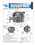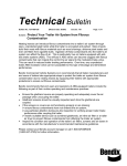
1
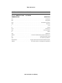
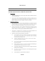
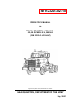
TM 9-2320-302-10
OPERATOR’S MANUAL
FOR
TRUCK, TRACTOR, LINE HAUL:
52,000 GVWR, 6 X 4, M915A3
(NSN 2320-01-432-4847)
Approved for public release; distribution is unlimited.
HEADQUARTERS, DEPARTMENT OF THE ARMY
May 2001
TM 9-2320-302-10
TECHNICAL MANUAL
TM 9-2320-302-10
HEADQUARTERS
DEPARTMENT OF THE ARMY
Washington, D.C., 28 May 2001
OPERATOR’S MANUAL
FOR
TRUCK, TRACTOR, LINE HAUL:
52,000 GVWR, 6 X 4, M915A3
(NSN 2320-01-432-4847)
REPORTING ERRORS AND RECOMMENDING IMPROVEMENTS
You can help improve this publication. If you find any mistakes or if you know of a way to
improve the procedures, please let us know. Submit your DA Form 2028 (Recommended
Changes to Equipment Technical Publications), through the Internet, on the Army Electronic
Product Support (AEPS) website. The Internet address is http://aeps.ria.army.mil. If you need
a password, scroll down and click on “ACCESS REQUEST FORM”. The DA Form 2028 is
located in the ONLINE FORMS PROCESSING section of the AEPS. Fill out the form and
click on SUBMIT. Using this form on the AEPS will enable us to respond quicker to your
comments and better manage the DA Form 2028 program. You may also mail, fax or e-mail
your letter, DA Form 2028 direct to: AMSTA-LC-CI/TECH PUBS, TACOM-RI, 1 Rock
Island Arsenal, Rock Island, IL 61299-7630. The e-mail address is: [email protected]. The fax number is DSN 793-0726 or Commercial (309) 782-0726.
TABLE OF CONTENTS
Page
Warning Summary . . . . . . . . . . . . . . . . . . . . . . . . . . . . . . . . . . . . . . . . . . . . . . . a
How to Use This Manual . . . . . . . . . . . . . . . . . . . . . . . . . . . . . . . . . . . . . . . . . iii
CHAPTER 1 INTRODUCTORY INFORMATION WITH THEORY OF OPERATION
WP 0001 00
WP 0002 00
WP 0003 00
General Information . . . . . . . . . . . . . . . . . . . . . . . . . . . . . . . . . . . . . . .0001 00-1
Equipment Description and Data . . . . . . . . . . . . . . . . . . . . . . . . . . . . .0002 00-1
Theory of Operation. . . . . . . . . . . . . . . . . . . . . . . . . . . . . . . . . . . . . . .0003 00-1
CHAPTER 2 OPERATING INSTRUCTIONS
WP
WP
WP
WP
0004
0005
0006
0007
00
00
00
00
Description and Use of Operator's Controls and Indicators. . . . . . . . .0004 00-1
Operation Under Usual Conditions . . . . . . . . . . . . . . . . . . . . . . . . . . .0005 00-1
Operation Under Unusual Conditions . . . . . . . . . . . . . . . . . . . . . . . . .0006 00-1
Stowage and Decal/Data Plate Guide. . . . . . . . . . . . . . . . . . . . . . . . . .0007 00-1
i
TM 9-2320-302-10
TABLE OF CONTENTS - CONTINUED
Page
CHAPTER 3 OPERATOR TROUBLESHOOTING
WP 0008 00
WP 0009 00
WP 0010 00
Troubleshooting Instructions . . . . . . . . . . . . . . . . . . . . . . . . . . . . . . . .0008 00-1
Troubleshooting Symptom Index. . . . . . . . . . . . . . . . . . . . . . . . . . . . .0009 00-1
Troubleshooting Procedures. . . . . . . . . . . . . . . . . . . . . . . . . . . . . . . . .0010 00-1
CHAPTER 4 OPERATOR MAINTENANCE INSTRUCTIONS
WP 0011 00
WP
WP
WP
WP
WP
0012
0013
0014
0015
0016
00
00
00
00
00
Preventive Maintenance Checks and Services (PMCS)
Introduction . . . . . . . . . . . . . . . . . . . . . . . . . . . . . . . . . . . . . . . . . . . . .0011 00-1
Preventive Maintenance Checks and Services (PMCS). . . . . . . . . . . .0012 00-1
Truck Cleaning and Refueling Instructions . . . . . . . . . . . . . . . . . . . . .0013 00-1
Wheel and Tire Maintenance Instructions . . . . . . . . . . . . . . . . . . . . . .0014 00-1
Battery Box Cover Replacement . . . . . . . . . . . . . . . . . . . . . . . . . . . . .0015 00-1
Lubrication Instructions . . . . . . . . . . . . . . . . . . . . . . . . . . . . . . . . . . . .0016 00-1
CHAPTER 5 SUPPORTING INFORMATION
WP
WP
WP
WP
0017
0018
0019
0020
00
00
00
00
References . . . . . . . . . . . . . . . . . . . . . . . . . . . . . . . . . . . . . . . . . . . . . .0017 00-1
Components of End Item (COEI) and Basic Issue Items (BII) Lists . .0018 00-1
Additional Authorization List (AAL) . . . . . . . . . . . . . . . . . . . . . . . . .0019 00-1
Expendable and Durable Items List . . . . . . . . . . . . . . . . . . . . . . . . . . .0020 00-1
Index. . . . . . . . . . . . . . . . . . . . . . . . . . . . . . . . . . . . . . . . . . . . . . . . . . . . Index-1
ii
TM 9-2320-302-10
HOW TO USE THIS MANUAL
This manual is designed to help you operate and maintain the M915A3 Tractor Truck.
FEATURES OF THIS MANUAL:
•
A Table of Contents is provided at the beginning of this manual.
•
WARNINGs, CAUTIONs, NOTEs, subject headings, and other important information are
highlighted in BOLD print as a visual aid.
WARNING
A WARNING indicates a hazard, which can result in death or serious injury.
CAUTION
A CAUTION is a reminder of safety practices or directs attention to usage
practices that may result in damage to equipment.
NOTE
A NOTE is a statement containing information that will make the procedures
easier to perform.
•
Statements and words of particular importance are printed in CAPITAL LETTERS to create emphasis.
•
Instructions are located with illustrations that show the specific task on which the operator
is working.
•
Dashed leader lines used in illustrations indicate that called out items are not visible (i.e.
they are located within the structure). Dashed leader lines in the Lubrication Chart indicate
that lubrication is required on BOTH sides of the equipment.
•
Technical instructions include metric units in addition to standard units. A metric conversion chart is provided on the inside back cover.
•
An alphabetical index is provided at the end of the manual to assist in locating information
not readily found in the Table of Contents.
FOLLOW THESE GUIDELINES WHEN YOU USE THIS MANUAL:
•
Read through this manual and become familiar with its contents before attempting to operate or maintain the truck.
•
A Warning Summary is provided
•
the beginning of this manual and should be read before attempting to operate or maintain
the truck.
iii/(iv Blank)
TM 9-2320-302-10
CHAPTER 1
INTRODUCTORY INFORMATION WITH
THEORY OF OPERATION
TM 9-2320-302-10
GENERAL INFORMATION
0001 00
SCOPE
1.
Type of Manual. This manual is for use in operating and maintaining the M915A3 Tractor Truck.
2.
Equipment Name and Model Number. Truck, Tractor, Line Haul: 52,000 GVWR,
6X4, M915A3.
3.
Purpose of Equipment. The M915A3 Tractor Truck is a 6 X 4 prime mover of semitrailers used primarily to transport containers, bulk cargo, and petroleum products over primary and secondary roads under worldwide climatic conditions in a military
environment.
MAINTENANCE FORMS, RECORDS, AND REPORTS
Department of the Army forms and procedures used for equipment maintenance will be those
prescribed by DA Pam 738-750, Functional User’s Manual for the Army Maintenance Management System (TAMMS), as contained in the Maintenance Management Update.
REPORTING EQUIPMENT IMPROVEMENT RECOMMENDATIONS (EIRs)
If your truck needs improvement, let us know. Send us an EIR. You, the user, are the only one
who can tell us what you don’t like about your equipment. Let us know why you don’t like the
design or performance. Put it on an SF Form 368 (Product Quality Deficiency Report). Mail it
to us at: Commander, U.S. Army Tank-automotive and Armaments Command, ATTN:
AMSTA-LC-CIP-WT, Rock Island, Illinois 61299-7630. We’ll send you a reply.
CORROSION PREVENTION AND CONTROL (CPC)
1.
Corrosion Prevention and Control (CPC) of Army materiel is a continuing concern. It is
important that any corrosion problems with this item be reported so that the problem can
be corrected and improvements can be made to prevent the problem in future items.
2.
While corrosion is typically associated with rusting of metals, it can also include deterioration of other materials, such as rubber and plastic. Unusual cracking, softening, swelling, or breaking of these materials may be a corrosion problem.
3.
If a corrosion problem is identified, it can be reported using SF Form 368 (Product Quality Deficiency Report). Use of key words such as “corrosion,” “rust,” “deterioration,” or
“cracking” will ensure that the information is identified as a CPC problem. The form
should be submitted to the address specified in DA Pam 738-750.
OZONE DEPLETING SUBSTANCES (ODS)
Listing to be provided by requiring activity.
DESTRUCTION OF ARMY MATERIEL TO PREVENT ENEMY USE
For destruction of Army materiel to prevent enemy use, refer to TM 750-244-6.
0001 00-1
TM 9-2320-302-10
GENERAL INFORMATION - CONTINUED
0001 00
PREPARATION FOR STORAGE OR SHIPMENT
For preparation for storage or shipment procedures, refer to TM 9-2320-302-20.
WARRANTY INFORMATION
The vehicle is warranted by Freightliner Corporation in accordance with TB 9-2320-302-15.
Warranty starts on the date found in block 23, DA Form 2408-9 in the logbook. Report all
defects in material or workmanship to your supervisor, who will take appropriate action.
NOMENCLATURE CROSS-REFERENCE LIST
COMMON NAME
OFFICIAL NOMENCLATURE
Cold Start System . . . . . . . . . . . . . . . . . . . . . . . . . . . . . . . . . . . . . . . . Ether Quick-Start System
Engine Coolant . . . . . . . . . . . . . . . . . . . . . . . . . . . . . . . . . Antifreeze, Ethylene Glycol Mixture
Gladhand . . . . . . . . . . . . . . . . . . . . . . . . . . . . . . . . . . . . . . . . . . . . . .Quick Disconnect Coupling
Jake Brake. . . . . . . . . . . . . . . . . . . . . . . . . . . . . . . . . . . . . . . . . . . . . . . . . . . . . . . . Engine Brake
Komfort Loc® . . . . . . . . . . . . . . . . . . . . . . . . . . . . . . . . . . . . . . . . . . . . . . Seat Belt Adjustment
TufTrac . . . . . . . . . . . . . . . . . . . . . . . . . . . . . . . . . . . . . . . . . . . . . . . . . Rear Suspension System
LIST OF ABBREVIATIONS
NOTE
Refer to MIL-STD-12D for standard abbreviations.
ABBREVIATION
DEFINITION
AAL . . . . . . . . . . . . . . . . . . . . . . . . . . . . . . . . . . . . . . . . . . . . . . . Additional Authorization List
ABS. . . . . . . . . . . . . . . . . . . . . . . . . . . . . . . . . . . . . . . . . . . . . . . . . . . . Anti-Lock Brake System
BII. . . . . . . . . . . . . . . . . . . . . . . . . . . . . . . . . . . . . . . . . . . . . . . . . . . . . . . . . . . Basic Issue Items
C . . . . . . . . . . . . . . . . . . . . . . . . . . . . . . . . . . . . . . . . . . . . . . . . . . . . . . . . .Centigrade or Celsius
CID . . . . . . . . . . . . . . . . . . . . . . . . . . . . . . . . . . . . . . . . . . . . . . . . . . . .Cubic Inch Displacement
cm . . . . . . . . . . . . . . . . . . . . . . . . . . . . . . . . . . . . . . . . . . . . . . . . . . . . . . . . . . . . . . . . Centimeter
COEI . . . . . . . . . . . . . . . . . . . . . . . . . . . . . . . . . . . . . . . . . . . . . . . . . . .Components of End Item
CWS . . . . . . . . . . . . . . . . . . . . . . . . . . . . . . . . . . . . . . . . . . . . . . . . . .Collision Warning System
ECU . . . . . . . . . . . . . . . . . . . . . . . . . . . . . . . . . . . . . . . . . . . . . . . . . . . . Electronic Control Unit
F . . . . . . . . . . . . . . . . . . . . . . . . . . . . . . . . . . . . . . . . . . . . . . . . . . . . . . . . . . . . . . . . . Fahrenheit
GCWR . . . . . . . . . . . . . . . . . . . . . . . . . . . . . . . . . . . . . . . . . Gross Combination Weight Rating
GVWR . . . . . . . . . . . . . . . . . . . . . . . . . . . . . . . . . . . . . . . . . . . . . .Gross Vehicle Weight Rating
kg . . . . . . . . . . . . . . . . . . . . . . . . . . . . . . . . . . . . . . . . . . . . . . . . . . . . . . . . . . . . . . . . . Kilogram
0001 00-2
TM 9-2320-302-10
GENERAL INFORMATION - CONTINUED
0001 00
LIST OF ABBREVIATIONS - CONTINUED
ABBREVIATION
DEFINITION
km . . . . . . . . . . . . . . . . . . . . . . . . . . . . . . . . . . . . . . . . . . . . . . . . . . . . . . . . . . . . . . . . . Kilometer
kPa . . . . . . . . . . . . . . . . . . . . . . . . . . . . . . . . . . . . . . . . . . . . . . . . . . . . . . . . . . . . . . . Kilopascal
kph . . . . . . . . . . . . . . . . . . . . . . . . . . . . . . . . . . . . . . . . . . . . . . . . . . . . . . . Kilometers per Hour
kW. . . . . . . . . . . . . . . . . . . . . . . . . . . . . . . . . . . . . . . . . . . . . . . . . . . . . . . . . . . . . . . . . . Kilowatt
l . . . . . . . . . . . . . . . . . . . . . . . . . . . . . . . . . . . . . . . . . . . . . . . . . . . . . . . . . . . . . . . . . . . . . . . Liter
lb . . . . . . . . . . . . . . . . . . . . . . . . . . . . . . . . . . . . . . . . . . . . . . . . . . . . . . . . . . . . . . . . . . . . . Pound
lb-ft . . . . . . . . . . . . . . . . . . . . . . . . . . . . . . . . . . . . . . . . . . . . . . . . . . . . . . . . . . . . . . . Pound foot
lph . . . . . . . . . . . . . . . . . . . . . . . . . . . . . . . . . . . . . . . . . . . . . . . . . . . . . . . . . . . . .Liters per Hour
m . . . . . . . . . . . . . . . . . . . . . . . . . . . . . . . . . . . . . . . . . . . . . . . . . . . . . . . . . . . . . . . . . . . . . Meter
mm . . . . . . . . . . . . . . . . . . . . . . . . . . . . . . . . . . . . . . . . . . . . . . . . . . . . . . . . . . . . . . . Millimeter
PMCS . . . . . . . . . . . . . . . . . . . . . . . . . . . . . . . . . Preventive Maintenance Checks and Services
psi . . . . . . . . . . . . . . . . . . . . . . . . . . . . . . . . . . . . . . . . . . . . . . . . . . . . . . Pounds per Square Inch
rpm . . . . . . . . . . . . . . . . . . . . . . . . . . . . . . . . . . . . . . . . . . . . . . . . . . . . . Revolutions per Minute
SINCGARS. . . . . . . . . . . . . . . . . . . . . . . . . . . .Single Channel Ground/Airborne Radio System
TMDE. . . . . . . . . . . . . . . . . . . . . . . . . . . . . . . . Test, Measurement, and Diagnostic Equipment
0001 00-3/(0001 00-4 Blank)
TM 9-2320-302-10
EQUIPMENT DESCRIPTION AND DATA
0002 00
EQUIPMENT CHARACTERISTICS, CAPABILITIES, AND FEATURES
1.
2.
Characteristics.
a.
The M915A3 Tractor Truck is used to transport M871, M872, and M1062 semitrailers on line haul missions.
b.
It has a Gross Vehicle Weight Rating (GVWR) of 52,000 lb (23,608 kg) and is
equipped with a two-way oscillating, sliding fifth wheel compatible with a two-inch
kingpin. Maximum towed load on kingpin is 30,000 lb (13,620 kg).
Capabilities and Features.
a.
While operating on Class I roads, the fully loaded M915A3 can maintain a speed of
65 mph (105 kph) on level roads and 29 mph (47 kph) while ascending a 3 percent
grade. It has a minimum turning diameter, curb-to-curb, of 53 ft 9 in (16.4 m).
b.
Average cruising ranges at Gross Combination Weight Rating (GCWR) with a full
tank of fuel will vary based on conditions (e.g., varying loads, prolonged idle, and
climatic conditions). Cruising range is optimally 400 miles (640 km).
c.
The M915A3 is equipped with an instrument panel mounted speedometer and
tachometer which register truck ground speed and engine speed.
d.
The M915A3 has the following capabilities and features:
(1)
air-activated front and rear non-asbestos cam brakes with a four-channel
anti-lock brake system (ABS) to provide significantly improved handling
and braking during emergency stops
(2)
operation in temperatures from -25°F (-32°C) to +125°F (+52°C), and to
-40°F (-40°C) with arctic kit installed
(3)
start and climb capability of a 20 percent grade at GCWR in both forward
and reverse directions
(4)
fording capability up to 20 in (51 cm) deep for 5 minutes without damage or
requiring maintenance before operations can continue
(5)
two-passenger aluminum corrosion-proof cab with a 90 degree tilt-forward
hood for service accessibility
(6)
six cylinder, 12.7 liter, 430 horsepower, in-line turbocharged diesel engine
built by Detroit Diesel
(7)
Allison HD 4560P six-speed automatic transmission
0002 00-1
TM 9-2320-302-10
EQUIPMENT DESCRIPTION AND DATA - CONTINUED
0002 00
EQUIPMENT CHARACTERISTICS, CAPABILITIES, AND FEATURES CONTINUED
(8)
e.
Collision Warning System (CWS) that warns the driver of potentially dangerous driving situations by activating visual and audible alerts.
When operating in arctic conditions, the M915A3 can be equipped with an arctic
heater mounted under the cab, above the battery box. This provides heat for the cab
and engine cooling system. The arctic heater may be operated prior to starting the
engine to provide preheating of engine block.
LOCATION AND DESCRIPTION OF MAJOR COMPONENTS
1
2
3
4
5
15
6
7
14
10
13
12
11
10
0002 00-2
9
8
TM 9-2320-302-10
EQUIPMENT DESCRIPTION AND DATA - CONTINUED
0002 00
LOCATION AND DESCRIPTION OF MAJOR COMPONENTS - CONTINUED
Key
Component
Description
1
Marker Clearance
Lights
Indicate outline of truck.
2
Side Mirrors (Heated)
Provide driver with a view of sides of truck and
semitrailer, if towing.
3
Grabhandles
Provide a hand hold for personnel climbing on truck.
4
Utility Power
Receptacle
Supplies power for work lights. Located on both
sides of truck.
5
Air Horn
Provides an audible alert.
6
Master Battery Switch
Connects batteries to vehicle electrical system.
7
Spare Wheel and Tire
Extra wheel and tire used in case of a flat tire.
8
Battery Box and
Steps
Holds vehicle batteries and provides steps to
access cab.
9
Front Service Lights
Include headlights and turn signals.
10
Bumper Extensions
Provide adjustable attachment point for slings.
11
Blackout Lights
Used during blackout conditions. Include marker
and drive lights.
12
Towing Eyes
Provide attachment points for towing device.
13
CWS Antenna
Forward looking collision warning system antenna.
14
Brush Guard
Protects front of hood and components under hood
from damage.
15
Spotting Mirrors
Provide added visibility to sides and front of truck.
0002 00-3
TM 9-2320-302-10
EQUIPMENT DESCRIPTION AND DATA - CONTINUED
0002 00
LOCATION AND DESCRIPTION OF MAJOR COMPONENTS - CONTINUED
18
20
19
21
3
22
17
16
23
24
31
29 30
25
29 28
27
26
Key
Component
Description
3
Grabhandles
Provide a hand hold for personnel climbing on truck.
16
Ramp
Sloped surface serves as an approach to fifth wheel
and facilitates coupling of semitrailer.
17
Fifth Wheel
Coupling device for semitrailers with kingpins.
18
Utility Lights
Illuminate area in back of cab. There is one light on
each side of cab.
19
Strobe Warning Light
Strobe light alerts other vehicles of presence of
truck.
20
Intervehicular
Receptacles
Installation
Contains 12-volt commercial, 24-volt military, and
trailer ABS receptacles.
21
Antenna Mount
Mount for radio antenna.
22
Exhaust Muffler
Deadens noise of engine exhaust.
23
Hood Latch
Locks hood closed. Located on both sides of hood.
0002 00-4
TM 9-2320-302-10
EQUIPMENT DESCRIPTION AND DATA - CONTINUED
0002 00
LOCATION AND DESCRIPTION OF MAJOR COMPONENTS - CONTINUED
Key
Component
Description
24
CWS Side Sensor
Side looking collision warning system sensor.
25
Fuel Tank
Holds fuel. Steps mounted to tank provide access
to cab.
26
Storage Boxes
Provide stowage area for BII and other items.
27
Mud Flaps
Prevent water and debris from spraying up on
passers by or towed semitrailer.
28
Blackout Lights
Used during blackout conditions.
29
Trailer Gladhands
Provide air supply for trailer brakes.
30
Pintle Hook
Coupling device for trailers with lunettes.
31
Taillights
Contain composite tail, stop, backup, and turn
signal lights.
0002 00-5
TM 9-2320-302-10
EQUIPMENT DESCRIPTION AND DATA - CONTINUED
0002 00
EQUIPMENT DATA
Dimensions:
Length (Overall) . . . . . . . . . . . . . . . . . . . . . . . . . . . . . . . .
276.0 in (701 cm)
Height (Overall). . . . . . . . . . . . . . . . . . . . . . . . . . . . . . . . .
118 in (300 cm)
Width (Overall) . . . . . . . . . . . . . . . . . . . . . . . . . . . . . . . . .
100 in (254 cm)
Wheelbase . . . . . . . . . . . . . . . . . . . . . . . . . . . . . . . . . . . . .
162 in (411 cm)
Ground Clearance . . . . . . . . . . . . . . . . . . . . . . . . . . . . . . .
9 in (23 cm)
Angle of Approach . . . . . . . . . . . . . . . . . . . . . . . . . . . . . .
27°
Weights:
Curb . . . . . . . . . . . . . . . . . . . . . . . . . . . . . . . . . . . . . . . . . .
19,080 lb (8662 kg)
GVWR . . . . . . . . . . . . . . . . . . . . . . . . . . . . . . . . . . . . . . . .
52,000 lb (23,608 kg)
GCWR . . . . . . . . . . . . . . . . . . . . . . . . . . . . . . . . . . . . . . . .
105,000 lb (46,670 kg)
Front Axle (Loaded) . . . . . . . . . . . . . . . . . . . . . . . . . . . . .
12,000 lb (5448 kg)
Rear Axle (Loaded) . . . . . . . . . . . . . . . . . . . . . . . . . . . . . .
40,000 lb (18,160 kg)
Capacities:
Engine Oil (Refill w/Filters) . . . . . . . . . . . . . . . . . . . . . . .
41 qt (38.81 l)
Cooling System . . . . . . . . . . . . . . . . . . . . . . . . . . . . . . . . .
65 qt (61.5 l)
Fuel Tank. . . . . . . . . . . . . . . . . . . . . . . . . . . . . . . . . . . . . .
100 gal. (378.5 l)
Power Steering Reservoir . . . . . . . . . . . . . . . . . . . . . . . . .
2 qt (1.9 l)
Transmission . . . . . . . . . . . . . . . . . . . . . . . . . . . . . . . . . . .
51 qt (48 l)
Rear Axle (Forward/Rear). . . . . . . . . . . . . . . . . . . . . . . . .
13/14.5 qt (12.3/13.7 l)
Engine:
Manufacturer . . . . . . . . . . . . . . . . . . . . . . . . . . . . . . . . . . .
Type . . . . . . . . . . . . . . . . . . . . . . . . . . . . . . . . . . . . . . . . . .
Detroit Diesel
4-stroke, in-line
turbocharged diesel
Model. . . . . . . . . . . . . . . . . . . . . . . . . . . . . . . . . . . . . . . . .
DDEC IV
Cylinders . . . . . . . . . . . . . . . . . . . . . . . . . . . . . . . . . . . . . .
6
Displacement. . . . . . . . . . . . . . . . . . . . . . . . . . . . . . . . . . .
755 CID (12.7 l)
Torque @ 1200 rpm. . . . . . . . . . . . . . . . . . . . . . . . . . . . . .
1400 lb-ft (1898 N·m)
Maximum Horsepower @ 2100 rpm. . . . . . . . . . . . . . . . .
430 (320.6 kW)
Maximum Governed Speed. . . . . . . . . . . . . . . . . . . . . . . .
2100 rpm
Oil Filter Type . . . . . . . . . . . . . . . . . . . . . . . . . . . . . . . . . .
2 full flow,
replaceable elements
Oil Filter Quantity . . . . . . . . . . . . . . . . . . . . . . . . . . . . . . .
0002 00-6
2
TM 9-2320-302-10
EQUIPMENT DESCRIPTION AND DATA - CONTINUED
0002 00
EQUIPMENT DATA - CONTINUED
Fuel System:
Type . . . . . . . . . . . . . . . . . . . . . . . . . . . . . . . . . . . . . . . . . .
diesel fuel injected
Fuel Filter Type . . . . . . . . . . . . . . . . . . . . . . . . . . . . . . . . .
1 primary, 1 secondary
replaceable element
Air Cleaner:
Type . . . . . . . . . . . . . . . . . . . . . . . . . . . . . . . . . . . . . .
Quantity . . . . . . . . . . . . . . . . . . . . . . . . . . . . . . . . . . .
dry element
1
Cooling System:
Radiator Working Pressure . . . . . . . . . . . . . . . . . . . . . . . .
10 psi (69 kPa)
Coolant Inhibitor Filter . . . . . . . . . . . . . . . . . . . . . . . . . . .
1 replaceable element
Electrical System:
Type . . . . . . . . . . . . . . . . . . . . . . . . . . . . . . . . . . . . . . . . . .
dual 12/24 volt
Batteries:
Quantity . . . . . . . . . . . . . . . . . . . . . . . . . . . . . . . . . . .
Voltage . . . . . . . . . . . . . . . . . . . . . . . . . . . . . . . . . . . .
4
12 volt
Transmission:
Manufacturer . . . . . . . . . . . . . . . . . . . . . . . . . . . . . . . . . . .
Allison
Model. . . . . . . . . . . . . . . . . . . . . . . . . . . . . . . . . . . . . . . . .
HD 4560P
Type . . . . . . . . . . . . . . . . . . . . . . . . . . . . . . . . . . . . . . . . . .
6-speed automatic
Shift Selector. . . . . . . . . . . . . . . . . . . . . . . . . . . . . . . . . . .
pushbutton
Front Axle:
Manufacturer . . . . . . . . . . . . . . . . . . . . . . . . . . . . . . . . . . .
Rockwell
Type . . . . . . . . . . . . . . . . . . . . . . . . . . . . . . . . . . . . . . . . . .
I-beam, FF961
Rated Capacity. . . . . . . . . . . . . . . . . . . . . . . . . . . . . . . . . .
12,000 lb (5448 kg)
Maximum Steering Angle . . . . . . . . . . . . . . . . . . . . . . . . .
32°
Rear Axle (Tandem):
Manufacturer . . . . . . . . . . . . . . . . . . . . . . . . . . . . . . . . . . .
Rockwell, RT 40-145P
Rated Capacity. . . . . . . . . . . . . . . . . . . . . . . . . . . . . . . . . .
38,000 lb (17,252 kg)
Ratio. . . . . . . . . . . . . . . . . . . . . . . . . . . . . . . . . . . . . . . . . .
4.44:1
Inter-axle Differential . . . . . . . . . . . . . . . . . . . . . . . . . . . .
bevel gear
Traction Control . . . . . . . . . . . . . . . . . . . . . . . . . . . . . . . .
air controlled
0002 00-7