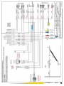
1
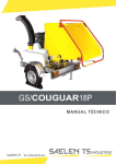
OPERATING MANUAL
TA B L E O F C O N T E N T S
INVENTION PATENT _________________________________ 5
INTRODUCTION__________________________________________ 6-7
SAFETY PRECAUTIONS__________________________________________________ 6-7
GUARANTEE____________________________________________________________ 8
LOCATION OF THE SERIAL NUMBER ____________________________________ 9
SAFETY ___________________________________________________________________ 10
GENERAL SAFETY AND MEANING OF THE LABELS _______________________
SAFE USE________________________________________________________________
SAFE MAINTENANCE____________________________________________________
SAFE TRANSPORTATION_________________________________________________
11-12
13
14
15
GENERAL DESCRIPTION AND FUNCTIONS ______________________ 16-18
OPERATION ____________________________________________________________ 19
STARTING _______________________________________________ 20
CHECKLIST ____________________________________________________________ 20
STARTING _____________________________________________________________ 21
STOPPING ______________________________________________________________ 22
MAINTENANCE___________________________________________ 23
RECOMMENDED LUBRICANTS___________________________________________
MAINTENANCE INTERVALS______________________________________________
LUBRICATION POINTS___________________________________________________
OIL LEVEL ______________________________________________________________
TENSION OF THE METAL BELT __________________________________________
VERIFICATION BELT AND SLIDING PLATE _______________________________
AIR INLETS OF THE ROTOR _____________________________________________
DISASSEMBLY TO REPLACE BLADES AND HAMMER INSERTS ____________
DISASSEMBLY TO CHECK THE COUNTERBLADES ________________________
ADJUSTMENT OF THE ROTOR BELTS ____________________________________
MAINTENANCE OF THE HYDRAULIC COUPLING _________________________
ADJUSTMENT OF THE BRAKES __________________________________________
23
24
25-27
28
29
30
30
31-32
33
34
35
36
DESCRIPTION AND MANIPULATION ______________________________ 37
DASHBOARD ____________________________________________________________
TANKS __________________________________________________________________
SAFETY CAPS ___________________________________________________________
MAINTENANCE/WORK SWITCH__________________________________________
EMERGENCY STOPS _____________________________________________________
GS/VIPER50DS
37
38
39
40
41
2014-10-06
3
TA B L E O F C O N T E N T S
ANTI-OBSTRUCTION SYSTEM "VarioStress": Description______________
ANTI-OBSTRUCTION SYSTEM: Programs _________________________________
ROTOR SENSOR ________________________________________________________
FUNCTIONING OF THE HYDRAULIC COUPLING AND ITS SAFETY
EQUIPMENT ____________________________________________________________
CO2 REDUCTION: (OPTION) Functioning __________________________________
CO2 REDUCTION: (OPTION) Starting ______________________________________
SPECIFIC FUNCTIONS OF CO2 RÉDUCTION_______________________________
DISCHARGE CHUTE _____________________________________________________
42
43-44
45
46
47
48-49
50
51
GENERAL PROBLEM-SOLVING_____________________________________ 52-53
PROBLEM-SOLVING CO2 RÉDUCTION_____________________ 54
SPECIFICATIONS_______________________________________________________ 55
HYDRAULIC COUPLING AND CHANGING THE ENGINE OIL _______ 56
HYDRAULIC SCHEDULE __________________________________ 57
ELECTRICAL CIRCUIT VIPER standard________________________ 58
ELECTRICAL CIRCUIT VIPER WITH CO2 REDUCTION_____ 59
ELECTRICAL CIRCUIT CO2 RÉDUCTION_____________________ 60
ELECTRICAL CIRCUIT MOTOR____________________________ 61-62
SPECIFIC FUNCTIONS: Use of the machine in manual mode_____ 63
CONFIRMATION OF CONFORMITY TS Industrie_____________ 64
GS/VIPER50DS
2014-10-06
4
PATENT FOR INVENTION
Intellectual property law-Books VI
GRANTING DECISION
The General Manager of the National Institute of industrial property has decided
that invention patent # ##-##### the text of which is appended shall be delivered to:
SAELEN S.N.S. Company - FR
The delivery produces its effects for a period of twenty years starting on the date
of deposit of the application, under reserve of payment of the annual royalties.
Mention of the delivery is made in the Official Bulletin of industrial property ###/## of
##:##:## (publication # # ### ###).
INTRODUCTION
Thank you for your purchase and your confidence in us.
It is important to read what follows in order for you to fully benefit from your purchase.
Although this machine is simple and easy to use, we recommend reading this manual before starting to use it.
In order to operate your multi-vegetation chipper in a safe, efficient and effortless manner,
you need to be familiar with the instructions for operation, maintenance and problemsolving that are described in this manual.
This manual describes all the functions of the VIPER chipper. Keep it within reach for
later reference. Please contact your reseller for more information, technical data or if you
want to order an additional copy of this manual.
Safety precautions:
This machine is only suitable for chipping vegetable waste. It may not be operated by
persons younger than 16.
The machine should only be used by persons who have a good physical condition and a
certain technical knowledge.
Maintenance must be done by a qualified technician. All interventions for assembly, disassembly and/or specific maintenance must be handled by a recognized distributor. Before
working on the VIPER for maintenance or other purposes, please remove the ignition key.
Position of the operator: left, right, in front of and behind in this manual are as
seen by the operator from his work station, facing the hopper.
F Front
L
R
Left
Right
B Behind
GS/VIPER50DS
2014-10-06
6
INTRODUCTION
Safety instructions
This machine is only intended for crushing and shredding plants.
Besides shredding wood and plants, the VIPER shredder cannot be used
for any other purpose.
The shredder should only be used by people over 16 years of age.
This machine can only be used by someone who is in good physical condition and who
has some technical knowledge.
Maintenance and repair work should be done by a qualified technician. Assembling,
disassembling and/or specific maintenance work should be performed by an authorized
dealer.
Before beginning work or proceeding to maintenance of the VIPER, always remove the
ignition key.
Proceed to maintenance by scrupulously following the instructions.
Eliminate pieces of metal, plastic, rubber or any other materials that may have been mixed
with the wastes.
Always use protection goggles, work gloves and protection against noise;
The machine can in no case be used to transport equipment, material or people.
The machine cannot be used to push or pull anything.
Battery acid is very corrosive. Avoid any contact with the eyes, skin and garments.
Immediately rinse eventual splashes with water and if the case arises, consult a doctor.
Before touching the electric circuit, always disconnect the cable connected to the battery’s +
terminal.
Always keep the battery out of reach of children.
When performing maintenance, do it in a sufficiently lit workshop.
Respect the safety standards prescribed in the motor’s user and maintenance manual.
Keep children away while the machine is in operation or when performing maintenance
work; Do not work in confined space. Do not run the motor in a non ventilated place (risk of
CO² intoxication)
GS/VIPER50DS
2014-10-06
7
L O C AT I O N O F T H E
SERIAL NUMBER
When ordering spare parts for replacement or if you need technical information, please
always have with you the serial number of your VIPER 50 shredder.
TS Industrie manufacturer’s plate is on the front left chassis.
The serial number is located at the
place indicated on the photo.
Serial number
GS/VIPER50DS
2014-10-06
8
GUARANTEE
The TS Industrie Company guarantees the parts of its VIPER shredders against any defect
that could affect their operating. The guarantee applies in all the cases where the damage is
not the result of improper use, abuse or negligence, accidental, act of God or any other
circumstance beyond the control of TS Industrie. This guarantee extends over a period of
one year starting on the date of delivery to the customer and is limited to the replacement of
defective parts and/or of labour.
GUARANTEE CLAIM
A claim in due form shall be presented to TS Industrie, by the origin purchaser for inspection
by an authorized representative of the company.
This guarantee does not apply to a shredder that has been modified out of our
workshops and that, according to TS Industrie standards, would be affected in its
operation, its safety and its service life.
This guarantee does not cover parts and accessories that are already under their
manufacturer’s guarantee and the servicing of which is covered by the latter’s
administration. Service items such as lubricants, belts, paint and similar are not subject to
guarantee.
USER MANUAL
The purchaser acknowledges having received instructions concerning the correct operation
of the shredder and also acknowledges that TS Industrie cannot assume any responsibility
resulting from the use of his product other than that described in the user manual supplied at
the time of the purchase.
DO NOT FORGET TO REGISTER YOUR GUARANTEE
OTHERWISE IT WILL BECOME INVALID.
GS/VIPER50DS
2014-10-06
9
SAFETY
You are responsible for the safe use and the maintenance of your plant shredder. You
should thus make sure that whoever uses, maintains and works with the appliance has
knowledge of the operating and maintenance methods as well as the safety measures to
apply as described in this manual. The user manual informs you on the security practices
to apply when using the plant shredder.
Remember that you are the person in charge of security. Efficient precautions will protect
you as well as those around you. Make sure that ANYONE working with this appliance
knows how to operate and maintain it. It is very important to prevent accidents. to avoid
injury, respect the security measures explained in this manual.
- Before using the plant shredder, an owner has the duty of giving the user
instructions to operators or eventual employees.
- This equipment’s most important safety device is a safe operator. It is an
operator’s duty to read and understand all the security and operating instructions and to
scrupulously follow them. The best way of avoiding accidents.
- No one is supposed to handle the MV VIPER shredder if they have not read and
understood the instructions on the subject. An operator without knowledge exposes
himself and others to risks of accidents.
- It is not allowed to modify the equipment in any way whatever. Any non
authorized modification could affect the operation or the security and eventually reduce
the equipment’s service life.
THINK CAUTION!
WORK IN COMPLETE SECURITY.
GS/VIPER50DS
2014-10-06
10
GENERAL SAFETY
1) Read and understand the user manual and all the
security symbols before operating, maintaining,
un-jamming or adjusting the shredder.
2) Keep a first aid kit in case of accident.
Keep it in a visible place.
3) Keep a fire extinguisher within reach in case of
need. Keep it in a visible place.
4) Use appropriate protection equipment. Here are a few suggestions,
but do not limit yourself just to this description:
-Helmet and ear protection
-Work shoes with steel non-skid soles
-Protective goggles
-Work gloves and waterproof
garments.
5) Never operate without the protector.
6) Keep people away and especially children, when you are using the
shredder
GS/VIPER50DS
2014-10-06
11
GENERAL SAFETY
Meaning of the labels (cont.)
Attention!
wheel.
Grip
Never enter the
hopper when the
engine is running.
Never open or
remove
the
inspection doors
and carters of the
cutting parts.
Minimum engine
speed
Maximum engine speed
Lubrication point
Rotation commands of the conveyor belt:
Chipping material (forward operation)
Stop the rotation of the feed rolls
Releasing material (backward)
GS/VIPER50DS
2014-10-06
12
SAFE USE
1) Read and understand the user manual as well as all the security signs before any
operating, servicing, adjusting, repairing or un-jamming manoeuvre.
2) Install and make sure that all the protectors and guards are well fixed before starting
or working.
3) Keep hands, feet, hair as well as clothing out of reach of parts in movement.
4) Before performing maintenance, adjustments, repairs or un-jamming of the machine,
put the engine in idle speed with the accelerator handle, wait till all moving parts have
stopped, stop the engine.
5) Place all controls to neutral before starting the machine.
6) Keep people away, especially children before starting.
7) Use protections appropriate to the work to undertake.
8) Always couple the machine horizontally.
To avoid making the machine swing, always
work in a horizontal position if the machine
is unhitched.
9) when shredding, risk of projections of
chips within a 10 metres radius.
GS/VIPER50DS
2014-10-06
13
SAFE MAINTENANCE
1) Follow all the indications in the user manual concerning operating, maintenance and
security.
2) Before performing any maintenance, adjustment, repair or un-jamming of the machine,
put the engine in idle speed with the accelerator handle, declutch the machine and wait till
all the parts in movement have stopped, stop the engine, remove the ignition key.
3) Make sure that all the protectors and guards are efficiently fixed after performing
maintenance or servicing the shredder.
4) Warning! Keep hands, hair and clothing out of reach of moving parts.
5) Install and make sure that all the protectors and all the guards are well fixed before
starting or working.
6) Never wear badly cut, too loose or shredded clothing when working on command system
components.
CONSIGNES DE FONCTIONNEMENT
Read the operating instructions before use
The fuel should be exempt of water and impurities.
Check the tightening of bolts after 30 h, then every 150 h.
Respect the lubricating periodicity
Do not un-jam the machine with the starter or the clutch.
GS/VIPER50DS
2014-10-06
14
SAFE TRANSPORT
1) Follow the highway code in force.
2) Ensure that your equipment is always equipped with working signalling lights that are clean and visible
to other drivers.
3) Reduce your speed on country roads and bumpy surfaces.
Wear of the coupling:
Check the wear indicator when coupling the machine.
Systematically repleace the had and/or the ball of the coupling of the
vehicle if the indicator is in the MINUS zone. You might loose the chipper
on a bump in the road or against a border.
YOU ARE RESPONSIBLE IN CASE AN ACCIDENT HAPPENS.
Head and/or ball of the
coupling OK
Head and/or ball worn
Hitching to a vehicle:
Always hitch the shredder in a horizontal position in order to prevent the
machine from tipping backwards AND check that the tow bar’s nut joints
are secure on a daily basis to prevent jolting which would damage the
hitch and tow system and reduce its lifespan.
GS/VIPER50DS
2014-10-06
15
GENERAL DESCRIPTION
A N D O P E R AT I O N
DESCRIPTION
The TS Industrie VIPER multi plant shredder is intended for the
shredding of plants and branches up to 6,70 inchs (170 mm) in
diameter.
The machine includes the following main components:
(A) : the chassis
(B) : the shredding unit
(C) : the engine and its various transmissions
(D) : the evacuation shaft
(E) : the soundproof cover
(F) : the metallic feed belt
GS/VIPER50DS
2014-10-06
16
GENERAL DESCRIPTION
A N D O P E R AT I O N
A. The chassis.
The shredder’s chassis serves as support to the various components of the VIPER. It
allows moving the machine independently.
B. The shredding unit.
It is composed of a feed hopper (1), a metallic belt (2), a feed roller (3) with serrated bars and a rotor that shreds materials.
1) Feed belt and roller:
They lead the material at constant speed toward the shredding rotor.
An anti-jam system stops it when the rotor’s speed descends too low (jamming at
shredding level), they are automatically
put in rotation when the rotor regains sufficient speed to shred correctly.
They can be activated in both rotation directions (forward and reverse
run) With red or black and yellow push
buttons a the backside of the feed hopper
Their rotation speed is adaptable with a
tooth wheel (4) at the left backside of the
security cover and will depend on the diameter of the material to shred
2) Shredding rotor:
Key element of the machine, it shreds the matter brought by the feed roller.
It is put in rotation by progressively activating the clutch levier.
Its speed is set.
GS/VIPER50DS
2014-10-06
17
GENERAL DESCRIPTION
A N D O P E R AT I O N
C. The engine and its drives
The diesel heat engine is located above the shredding unit, it supplies the energy needed to
drive the rotor and to drive the hydraulic circuit’s oil pump.
It is a four-cylinder Kubota diesel engine. It develops 50 HP at 2900 rpm. For any
additional information on this engine, please refer to the manufacturer’s manual.
The outlet shaft is equipped with a pulley activating 3 belts that drive the shredding rotor’s
rotation.
The hydraulic circuit’s oil pump located on the diesel engine; activates the hydraulic drives
of the belt/feeder unit.
GS/VIPER50DS
2014-10-06
18
GENERAL DESCRIPTION
A N D O P E R AT I O N
OPERATING OF FEEDER CONTROLS
The VIPER is equipped with an electric command hydraulic distributor activated by ‘mushroom’ pushbuttons for the forward and reverse drives and a
red ‘hand rail’ command bar for stopping the feed roller / belt unit.
REM: to
make the feed roller / belt unit run in forward drive the engine’s speed should be at its maximum
FORWARD RUN COMMAND
1: To make the feed roller run in forward
drive the red handrail should be pulled backward
2: Press the yellow pushbutton to make the
feed roller run in forward drive
FEEDER STOP COMMAND
1: Push the red handrail to stop the feed
roller.
(the handrail can be locked in pulled position
and in pushed position)
REVERSE RUN COMMAND
1: To make the feed roller run in reverse
drive, first pull the handrail backward
2: And press the black pushbutton
REM: the feeding cell can be switched directly from forward to backward operation and vice versa without using the operating handle.
GS/VIPER50DS
2014-10-06
19
S TA R T I N G
CHECK BEFORE STARTING
Every operator should read and understand all the inscriptions and should follow the safety
measures described in this section for sure and efficient shredder operating. A checklist
prior to use is supplied to the user. It is important to take it into account for the security of
all as well as to keep the machine in good condition.
The following points should be checked before using the machine:
1) Is the machine sufficiently lubricated according to the lubrication plan indicated in the
user’s manual.
2) Check the different levels for the engine, being:
the engine’s oil level
the radiator’s water level
the gas oil level
3) Check the hydraulic circuit’s oil level.
4) Make sure the air filter is clean.
5) Make sure the engine’s radiator is not clogged up.
6) Make sure the covers are all closed and locked.
GS/VIPER50DS
2014-10-06
20
S TA R T I N G
WARNING!
If for an unknown reason the shredder has difficulty shredding the
material, and that you have to stop it: do not start the engine
again without having eliminated the cause and cleared the
material out of the shredding rotor!
PUTTING IN SERVICE
1) Check that the cap at the top end of the shaft is open.
2) Place the engine’s accelerator handle at idle.
3) Preheat and start the engine by turning the ignition key.
4) Slightly accelerate the engine’s speed. Let the engine’s
temperature rise.
5) Progressively engage the rotor’s clutch handle upwards.
Make sure the cutting rotor is placed in rotation and that it
is not jammed by residual material . Never try to clear it
with the clutch, which would prematurely damage it (see
stopping advice on the next page et page 45)
6) Pull the control bar (1) stopping the feeder right home in rear
position .
7) Put the feed roller in rotation by activating the yellow
control pusher located on the rear left of the branches intake
hopper.
8) Start shredding.
GS/VIPER50DS
2014-10-06
21
S TA R T I N G
STOPPING
1) Let the shredder empty itself for a few minutes to eliminate residual
materials behind the feed roller and inside the shredder, which could jam
on the rotor at the next start. (see advice page 45 )
2) Put forward the control bar to stop the feed roller and the carousel.
3) Progressively bring back the throttle lever to idle.
4) Stop the engine by turning the ignition key on the control panel.
GS/VIPER50DS
2014-10-06
22
MAINTENANCE
MAINTENANCE SECURITY
1) Put the parking brake on, remove the ignition key and wait till all the moving parts
have stopped before performing maintenance or repairs.
2) Make sure you put back all the protection screens after servicing.
LUBRICANT quantities:
Diesel motor: 9,5 L.
Fuel: 45 L.
Hydraulic oil: 24 L.
Hydraulic meter oil: 2,4 L.
Hydraulic reductor feed roller: 1 L.
Recommended LUBRICANT:
1) Lubricant for the hammers of the rotor:
You must use a water-resistant lubricant of type NLGI grade 2
"SAELEN BIOPLEX "
2) Lubricant for bearings, transmission belts and different organs:
Use a versatile high grade SAE lubricant that is compatible with extreme pressures
"SAELEN BIOPLEX "
3) Hydraulic oil:
Use oil AFNOR NFE 48600 Types HV iso VG 46
"MINERVA BIO HYDRO 46 "
4) Oil for hydraulic coupling
Use oil AFNOR NFE 48600 Types HV iso VG 46
"MINERVA BIO HYDRO 46 "
5) Engine oil
Use SAE 15W40 which complies with the standards: API CH4-CG4-CF
"MINERVA POWER LONG WAY 15W-40 "
6) Oil feeding reduction valve:
SAE 90 EP
GS/VIPER50DS
2014-10-06
23
MAINTENANCE
MAINTENANCE PERIODICITY
# of hours
Daily
Every 15
Every 50
Every 150
Servicing
-Check engine’s oil level
-Check radiator’s water level
-Check air filter’s degree of clogging
-Check radiator’s degree of clogging
-Lubrication of rotor’s hammers
-First engine oil change
-Lubrication of the rotor’s two rotations
-Cleanliness check of the air intake under the rotor
-Check if blades and hammers
-Check tension of rotor drive belts
-Lubrication of feed roller’s rotation
-Check level of hydraulics oil
-Check metallic belt’s tension (the first time at 8h)
-Engine oil change (or once a year)
-Lubrication of the metallic belt’s forward and reverse rollers
-Lubrication of feeder articulation axis bearings
-Replacement of hydraulic oil filter the first time and afterward
every 500 hours (or every 2 years)
-Check of counter-blade wear
-Check and remove the branches winding around the bearings'
axes and the hydraulic motors
-Check tightening of coupler head’s articulations
Every 300
-Replacement of gas-oil filter
-Check of belt and slide plate wear
-Check battery’s electrolyte level
-Check tension of alternator’s belt
-Check oil level of feed roller gearbox
Every 400
-1st coupler oil change , then every 1000 hours (or every 2
years)
Every 500
-Change hydraulic oil (or every 2 years)
-Chance hydraulic return oil filter (or every 2 years)
-Change hydraulic oil suction strainer (see page 40)
-Change feed roller gearbox oil
GS/VIPER50DS
2014-10-06
24
MAINTENANCE
LUBRICATION POINTS
Proceed to the lubrication and maintenance of the machine engine stopped and
ignition key removed.
LUBRICATION OF HAMMERS:
To access the rotor:
-Remove the two Nylstop locking nuts
-Open the evacuation shaft by making it pivot on
its two hinges.
-Clean the lubrication holes at the rear of
the hammers with a small screwdriver or
an air gun.
-Lubricate the 14 hammers
lubricant of type NLGI grade 3
compulsory
note: Do not grease excessively; ~2
pump shots per lubricator are sufficient.
Excessive lubrication would entail at the
rotor’s rotation, the centrifugation of
excess grease against the shaft’s inner
wall and deficient sliding of shredded
matter.)
LUBRICATION OF THE ROTOR’S
ROTATION BEARINGS
GS/VIPER50DS
2014-10-06
25
MAINTENANCE
LUBRICATION POINTS
LUBRICATION OF THE FEED
ROLLER’S BEARING
LUBRICATION OF THE TWO
BEARINGS OF THE BELT’S FRONT
ROLLER
LUBRICATION OF THE TWO
BEARINGS OF THE BELT’S REAR
ROLLER
LUBRICATION JOINT AXLE ARM
FEED ROLLER
GS/VIPER50DS
2014-10-06
26
MAINTENANCE
LUBRICATION POINTS
LUBRICATION OF FEEDER ARM’S
ARTICULATION AXIS
COUPLER HEAD’S BRAKE LINKAGE
ADJUSTABLE JOCKEY WHEEL
GS/VIPER50DS
2014-10-06
27
MAINTENANCE
OIL LEVELS
FEEDER REDUCTION GEAR LEVEL
(Oil should slightly flow at the cap’s orifice)
HYDRAULIC TANK LEVEL
ENGINE’S OIL GAUGE
(to change oil see page 56)
GS/VIPER50DS
2014-10-06
28
MAINTENANCE
SETTING THE METALLIC BELT’S TENSION
1
2
3
For good belt engagement, check
its tension after 8h and regularly
afterwards.
1 Belt correctly tightened
2 Belt loose
3 To tighten the belt loosen the 4 screws
on either side rep. (A) and simultaneously tighten the tightener rep. (B) so that the belt
is parallel to the unit’s base (see photo 1). Retighten the screws (A). After tension, run
the belt several times in forward and reverse directions to make sure it remains in line.
(Before tension make sure the belt is well centred in the hopper)
Rem.: do not tighten too much, a good grip of the feed roll
and belt does not require excessive tension.
GS/VIPER50DS
2014-10-06
29
MAINTENANCE
BELT AND SLIDING PLATE CONTROL
1
2
New plate
Used plate
To check the wear of the belt and of the self lubricating polyethylene sliding bearing, completely slacken the belt, lift it with a hook and check:
1
the bearing’s thickness above its four attachment screws
2
the wear of the belt’s strips
THE ROTOR’S AIR INTAKE VENTS
The VIPER has another air intake under the rotor in addition to the usual two in order to improve the rotor’s ventilation so as to optimise the ejection of shredded matter at the shaft’s
outlet
Regularly check the cleanliness of the three air intakes so as to optimise the ventilation
and the ejection of shredded material.
GS/VIPER50DS
2014-10-06
30
MAINTENANCE
DISASSEMBLY FOR REPLACEMENT OF BLADES AND
HAMMER PELLETS
Imperatively remove the ignition key for this type of servicing.
-The hollow hexagonal screws of the blades and hammer inserts are mounted at the
manufacture without Loctite at a torque of 16 M. Kg (157 N.m). Use the appropriate
wrench that is in good condition to remove them.
-Open the chute as described on previous page.
-Remove the screws from blades and inserts. (For the assembly later on, only use the news
screws category 12.9).
-Clean the contact surfaces of the blades and the inserts clean at the base (1) as well as the
wall (2).
GS/VIPER50DS
2014-10-06
31
MAINTENANCE
-Remount sharpened or new blades of identical weight.
IMPORTANT: Sharpening should be done by a professional on a machine specially adapted
for that, and not with a grinding machine.
Also see to it that the angle of 35° of the cutting edge is respected.
The minimum length (A) after sharpening should not be inferior to 50 mm. (The length of a
new knife is 60 mm).
-Tighten the screws class 12.9 to 16 M.kg torque (157 Nm)
and make sure the blades and inserts lean against the wall.
-Grease the axes of hammers (~2 grease gun shots per hammer).
-Close the shaft and the hoods.
-Start the engine and let it rise in temperature for a few minutes.
-Put in the rotor in gear progressively and accelerate up to maximum speed to make sure that
no abnormal vibration disturbs the machine’s operation.
GS/VIPER50DS
2014-10-06
32
MAINTENANCE
DISASSEMBLY TO CONTROL THE COUNTER-BLADE
Imperatively remove the ignition key for this type of servicing.
-Remove the two attachment screws (1) at each end of the counter knife.
-Remove the two safety bolts (2)
-Drive the knife out by sliding it in its housing on either side. If the edge is worn out remove
the wheel and the mudguard; take the counter-knife out of its housing, and remount it by
shifting it by a half turn so as to show a new edge facing the knives.
(The counter-knife can be taken out on the right or on the left side)
(Each of the counter-knife’s four edges that can be used)
GS/VIPER50DS
2014-10-06
33
MAINTENANCE
ADJUSTMENT OF THE ROTOR’S BELTS
The rotor’s belts are permanently kept extended by an extender.
To tighten the belts, loosen the nut (1) of the tensioner, loosen and remove the nut cons (2)
of the tension screw, move forward the tensioner using the nut (3) .
After belt tension, tighten the nuts (1) and (2).
This procedure should be carried out by a qualified technician.
GS/VIPER50DS
2014-10-06
34
MAINTENANCE
MAINTENANCE OF HYDRAULIC COUPLER
The VIPER is fit out with a hydraulic coupler
that needs no special maintenance with a usual
functioning.
Positioning of the security contactor
Oil change
Security green 180° C
Change the oil via the green cap (First
purge the couplyng by unscrewing the top cap)
Oil level
Filling
Security spring red 145° C
Oil
level
Refill the oil (1.14l.) by the detention
stopper or the green fuse cap
Place the mark 45 (corresponding to a filling
of 45°) vertically to the axe of the coupler.
Remove the detention stopper, for the right
level the oil must be just under the hole
GS/VIPER50DS
2014-10-06
35
MAINTENANCE
ADJUSTMENT OF BREAKING TRANSMISSION
-Place the brake lever in released position.
-Check the clearance between the latch
activating the brake cable and the push piston.
The clearance should be about 2mm.
-To adjust the clearance; act on the tightener:
*loosen the nut.
(left hand thread)
*turn the rod
till you obtain the desired clearance.
*retighten the nut
GS/VIPER50DS
2014-10-06
36
DESCRIPTION AND
M A N I P U L AT I O N
ENGINE DASHBOARD
A : Green warning light functioning OK (If flashing, the engine stops after 10 seconds )
B: Warning light battery load
C: Warning light oil pressure
D: Warning light water temperature
E: no utility or preheating 8 seconds
F: Key switch
The engine is stopped automatically if warning light C and D indicate a problem
Motor stopped
Preheat
Start
Do not add the key of the chipper to a heavy
ring; during functioning this could interrupt
contact. The functioning in F and B direction of
belt/feed can be reset and the power supply to
engine can be interrupted.
key
the
the
the
GS/VIPER50DS
2014-10-06
37
DESCRIPTION AND
M A N I P U L AT I O N
THE RESERVOIRS
The machine has two reservoirs:
-the hydraulic oil reservoir including:
-The filler cap (1)
-Hydraulic filter on return (2)
-The hydraulic filter suction (3)
(accessible by removing the suction port)
-The level gauge (4)
-The transparent gas-oil reservoir 45 l.
GS/VIPER50DS
2014-10-06
38
DESCRIPTION AND
M A N I P U L AT I O N
SAFETY HOUSING
The machine has security devices on the opening of hoods:
An inductive pick-off (1) placed on the hood’s right door. The electric contact is made when
the magnet (2) fixed on the left door of the hood is approached.
When you open either one of the doors the security device stops the diesel engine.
There should be no physical contact between the pick-off and its magnet. On the other
hand, respect a functional clearance between the two of 5 to 15mm.
There may be no physical contact between sensor
and magnet. There must be 0,24 (+/- 0.20) in (6 mm+/5) play.
6mm
+/-5
During an intervention on the engine for which it is requireed to run with open cover
(only by a trained technician) this device can be bypassed through switch (3) (please
see the next page)
GS/VIPER50DS
2014-10-06
39
DESCRIPTION AND
M A N I P U L AT I O N
MAINTENANCE / OPERATING CONTACTOR
MAINTENANCE
When the engine requires and
intervention and it must run
with open cover (only by a
trained technician) it is possible to bypass this device by
switching the switch to the
top position (maintenance).
N.B.: In that position the engine can run but the feed roller will not rotate whatever the
engine’s speed. If after servicing the technician forgets to re-toggle the switch in lower
position, the user will not be able to run the machine. He will be obliged to re-toggle the
contactor in operating position and close the hoods to be able to start the engine.
In normal operation, the work/
maintenance switch is in the
bottom position (work)
WORK
When the cover is opened while the engine is running, the
sensor on the left door stops
the diesel engine.
GS/VIPER50DS
2014-10-06
40
DESCRIPTION ET
M A N I P U L AT I O N
EMERGENCY STOP BUTTONS
The machine also has two emergency circuit breaker buttons placed at the top of each side
of the feed hopper.
When they are activated, these emergency circuit-breakers have two functions:
1) stopping the diesel engine
2) instantly stopping the forward run of the feed roller and the belt
GS/VIPER50DS
2014-10-06
41
DESCRIPTION AND
M A N I P U L AT I O N
VarioStress ANTI-JAM SYSTEM
The VIPER is equipped with a controller of the rotation of the rotor that is linked to an
automat. Hence, we can prevent the machine from being blocked: permanent information
about the rotating speed of the rotor is being sent to the VarioStress. When the rotor speed
falls below a factory-set threshold, the hydraulic supply of the feed is interrupted. The feed
and belt will stop, the machine will no longer be fed material and the engine can reach its
working speed agian (2700T/mn). When the speed exceeds the lower threshold, the feed
roll and belt are supplied with oil again and the engine starts running again.
There are three anti-obstruction settings: see the next page
The
distance
between the speed
controller (1) and
the pulse device (2)
is 0,16 to 0,20 in (4
à 5 mm).
An automat (3) controls
the No Stress anti-jam
system’s solenoid valve.
It is located with the
protection fuses (5) (1
amp.) and (4) (10 amp.)
in the distribution box
located on the hopper’s
right front part.
The primary circuit’s protection fuse (6) (10
amp.) is in the watertight fuse-holder on the
starter cable.
GS/VIPER50DS
2014-10-06
42
DESCRIPTION AND
M A N I P U L AT I O N
ANTI-OBSTRUCTION SYSTEM VarioStress:
Different settings:
The VarioStress
anti-obstruction system has three preset configurations.
The user can choose the one that is most appropriate for
the material at hand.
Configuration 1: favours functioning at a wide range of motor speeds, mainly suitable
for chipping branches and light amterials
Configuration 2: suitable for manipulating mixed materials consisting of branches,
vegetation and conifers.
Configuration 3: a higher engine speed to improve ventilation for chipping plants and
confers or heavy and dense materials during a long period of time
Program n°
GS/VIPER50DS
2014-10-06
43
DESCRIPTION AND
M A N I P U L AT I O N
ANTI-OBSTRUCTION SYSTEM VarioStress: cont.
Selecting a setting:
- Engine is on or off, contact is engaged
Use Keys 1,2.3 to display the requested page.
1
2
3
Rem.: push during 1 to 1,5 seconds to change the program.
-Continuous Display of the Engine Rotation/
Operating Speed
-Display of functioning / running hours is
done by pressing the h Key of the Motor
(engine off or on)
Functioning/running
time count can only
be performed if the
chipper
shredder
rotor is in motion
Press the key for about one second
See Use of the machine in manual mode on page 61
+ intervention technician p.52
GS/VIPER50DS
2014-10-06
44
DESCRIPTION AND
M A N I P U L AT I O N
SENSOR NO ROTOR ROTATION
The VarioStress sensor (1) is also used to monitor the rotating movement and complements
the thermal safety (mark (2) on the next page). It stops the diesel engine by cutting off the
fuel supply if the rotor does not rotate after starting the engine.
10 seconds after supplying tension if the contact remains switched on without an attempt to start the engine. The electrical power supply from the automaton is interrupted automatically and the engine cannot start.
10 seconds after starting the engine this sensor checks the rotatino of the
rotor. If the rotor has not exceeded 60 r/mn after this time (minimale intervention threshold)
the sensor will shut the diesel engine down and cut off the electricity supply from the automaton. Check why the rotor has been blocked (residual material), set the contact to zero
and restart.
Please note that if the engine stops
after 10 seconds, you must always
try to find the cause of the
problems. Do not try to start the
engine multiple times. Since the
engine runs during 10 seconds at
every attempt, the coupling
temperature will continue to rise
and activate the safety (2) (next
page)
The distance between the sensor (1) and the index
(2) must be 0,16 to 0,20 in (4 to 5 mm)
See Use of the machine in manual mode on page 61
+ intervention by technician p.52
GS/VIPER50DS
2014-10-06
45
DESCRIPTION AND
M A N I P U L AT I O N
HYDRAULIC COUPLING
FUNCTIONING OF THE HYDRAULIC COUPLING
The Westcar coupling is a hydrodynamic coupling
according to Föttinger’s principle. It mainly consists
of two paddle wheels (pump and turbine) and an
external housing. The two paddle wheels are
supported by bearings. The power is transmitted
without hardly any wear because there is no
mechanical contact between the elements. The
coupling contains a constant quantity of liquid. The
mecanical energy of the drive engine is transformed into kinetic energy in the connected wheel pump.
This kinetic energy is again transformed into mechanical energy in the turbine wheel.
THERMAL SAFETY 145° and 180°
In case of abnormal overheating of the internal
oil of the coupling (above 140°C), the thermal
fuse (2) releases an axis that moves the handle
(3) of the switch of the thermal safety (1) . This
switch interrupts the fuel supply which stops the
engine. To restart, the thermal fuse (2) must be
replaced and the handle (3) must return to its original position.
If the engine is blocked when the machine is started (e.g. by a branch if the
machine was not correctly emptied at the last stop), the switch does not
work. The coupling is not rotating, the oil temperatur in the coupling quickly rises and is ejected through the green cap that melts at temperatures
over 180°C.
In order to prevent this inconvenience, an additional safety has
been provided (see previous page).
If the safety (2) is activated, always investigate the cause of the
problem. Never attempt the start the engine several times. The
temperature inside the coupling will continue to rise and
eventually the green cap will melt (180°). The oil is then ejected.
(This fuse cannot be reset and must be replaced).
GS/VIPER50DS
2014-10-06
46
DESCRIPTION AND
M A N I P U L AT I O N
Functioning of the CO2
REDUCTION system (option)
The chipper is a machine that is permanently
working at full engine speed. The periods of
chipping are alternated with passive idle
moments, the duration of which depends on the
configuration of the works. Hence, the noise,
the fuel consumption and the emission of CO2
are at maximum levels.
In order to avoid these inconveniences and in view
of the environemnt, every time the operator leaves
the chipper the CO2 REDUCTION system will
automatically switch the engine to idle after a
certain amount of time. That will reduce the
nuisance considerably. As soon as the CO2
REDUCTION radar detects that the operator
approaches the hopper to put branches in it, the
engine returns to its maximum speed. At the same
time, the feed belt/roll starts to rotate again after
two seconds in order to resume chipping.
In addition to the mentioned environmental
advantages, the CO2 REDUCTION SYSTEM also
makes it possible to increase the life span of all
moving parts of the machine: diesel engine,
transmission, feed belt, feed roll, engines and
hydraulic circuits.
See use on the following pages
GS/VIPER50DS
2014-10-06
47
DESCRIPTION AND
M A N I P U L AT I O N
Presence detector
Dead zone
The presence detector at the back of the housing detects the
operator up to 2 m behind the hopper with a width of approximately 1,10 m. The hopper area is a dead zone that is not taken into consideration by the detector. Objects in this area
will not accelerate the diesel engine or the rotation of the feed
belt/roll.
All objects, even inert ones, e.g. a wall or a vehicle at less than 2
m behind the chipper will generate the automatic acceleration of
the engine.
Using the machine with the CO ² reduction:
-Start the engine and heat
Gear handle high, idle
-Remain push 1 second on the yellow button ( forward feed roller ), engine accelerate, CO² reduction system and feed roller advance are now activate, you could release the button & start to
work.
- The engine will remain accelerate until the worker being at the
back the feeding hopper.
- If it’s move away from the machine, the engine will return to the
idle after a laps time defined by the coil coder button position.
- The engine will accelerate automatically when the worker will be
detectected again at the back the feeding hopper.
To switch off the CO² Reduction system, push 1 second on the
black button ( backward feed roller ).
The engine will return to the idle.
Using the machine without the CO ² reduction:
-Start the engine and heat few minutes.
- Accelerate the engine to maximum speed with the gear handle.
- Order the forward & backward operations ( feed roller & belt ) to
push normaly & briefy on the yellow & black button.
GS/VIPER50DS
2014-10-06
48
DESCRIPTION AND
M A N I P U L AT I O N
Access to the setting wheel:
The wheel numeric is protected
from the weather by a waterproof
cover
Setting wheel
The duration of the maximum speed must be
determined by the operator. (The modification is valid as of
the next start)
Four different configurations are possible, set by means of the
numbers on the setting wheel.
-Shut down contact and choose the working time with the +
and—keys of the setting wheel:
- 1 = 15 seconds at maximum speed
- 2 = 30 seconds at maximum speed
- 3 = 1 minute at maximum speed
- 4 = 2 minutes at maximum speed
(Do not use n° 0 and 5 to 9)
Example: The figure shows program 1, the diesel engine will idle until
15 seconds after the user has left.
Sensor opening feed for end of chipping
If the user has left the chipper and the time delay ends whilere
there is still material being fed by the belt/roll, a sensorsensor (A)
is activated for the opening of the feed equipment. It prolongs the
time delay with the same amount of time as the setting wheel.
Example: Delay at 1= 15sec.: the user leaves after 14 seconds
while there is still chipping material on the feed belt. After 15 sec,
the sensor will prolong the maximum speed during another 15
seconds.
Setting sensor (A), inlet at
the bottom: 0,70 inch
18m
m
GS/VIPER50DS
2014-10-06
49
DESCRIPTION AND
M A N I P U L AT I O N
The 15 Amp
fuse of the gear
equipment is in the
enclosed fuse holder
next to the alternotor.
Specific information on the functioning of CO2 Reduction:
Temporary interruption of the presence detector:
The atmosphere contains an impressive number of waves and magnetic fields that sometimes
interfere with the presence detector and thus prevent the automatic restart of the engine. To
prevent that, the operator can force the activation of the acceleration for a duration that is
determined by the setting wheel. The operator must support 1 second on the yellow button
to start the acceleration
Interference with the presence detector:
-Never modify the height of the containing lips
-Never modify the inclination of the radar holder
-Never put branches on the holder of the lips
-Automatic acceleration of the engine in case of very heavy rainfall
GS/VIPER50DS
2014-10-06
50
DESCRIPTION AND
M A N I P U L AT I O N
EVACUATION SHAFT
The top part of the discharge chute can be oriented 90° to the left and 90° to the right via
the indexer
GS/VIPER50DS
2014-10-06
51
P R O B L E M - S O LV I N G
In this section, we provide a list of problems, their causes as well as possible Solutions. If you experience a
problem that is not mentioned here, please contact your reseller. Keep your user manual and the serial
number of your chipper at hand.
INTERVENTION BY A TECHNICIAN ON THE ELECTRICAL CIRCUIT:
Since 2008 all TS Industrie chippers offer the possibility to shunt rotation controller
M18 of the rotor. The technician can then investigate an electrical fault on the
machine without starting the engine (see p. 45). The shunt will stop automatically
when the contact is broken.
Check the TS Industrietechnical customer service in your area or the TS Industrie
after sales department. They will explain how to shunt controller M18.
PROBLEM
The engine will not start.
CAUSE
SOLUTION
-Safety of the coupling activa- -See page 45 and 46
ted.
-Safety of the emergency but- -Turn off the safety.
ton activated.
-The cover is open.
-Check if the covers are closed
-The safety sensor of the co- -Check them (see p.39)
ver is defect.
-Fuse melted in the branch -Replace the fuse.
box.
-The battery is low.
-Load or replace the battery
-The power cables have been -Check the electrical cirdamaged.
cuits.
-The electrical valve that stops -Check the valve.
the engine is broken.
Reduced engine power
-Filter blocked
-Replace the filter
-Blades and hammers blunt
-Grind or replace the blades. Replace the hammer
inserts.
GS/VIPER50DS
2014-10-06
52
P R O B L E M - S O LV I N G
PROBLEM
CAUSE
SOLUTION
The engine stops early and -The cover is not properly
closed.
will not start again
-The safety of the coupling is
activated.
-The red light of the water
temperature is on.
-The safety sensor of the cover is defect.
-There is no fuel left.
-Check if the covers are closed properly.
-See page 45 and 46
switch
work/
The belt/roll will not rotate - T h e
maintenance is in the mainforward or backward
tenance position
-Fuse melted in the branch
box or the fuse holder on the
large starter cable (see p.42)
-Speed wheel feeding equipment completely tightened
-Hydraulic engine or pump
defect
-Not enough oil in the tank
-Set the switch to the work
position (see p.40)
The rotor will not rotate -No oil left in the coupling
while the engine is working -Belts defect or insufficiently
tightened
-Rotor blocked
-Check the oil level
-Replace and/or tighten the
belts
-See page 22
-The radiator is dirty: clean
-Check it (see p.39)
-Add fuel
-Replace the fuse
-Loosen the setting wheel on
the distributor
-Check or replace the defect
part
-Check the oil level
The machine has problems -Blades and hammers blunt
chipping
-Grind the blades or replace
them. Replace the hammer
inserts.
-Coupling oil level too low
-Supplement the oil level.
-Belts defect or unsufficien- -Replace and/or tighten the
tly tightened
belts.
-Anti-obstruction system out -Check the fuses p.42
of service
Feeding in forward opera- -electrical or hydraulic pro- -Please contact the seller
tion is not regulated, not blem
even below the VarioStress
intervention threshold
GS/VIPER50DS
2014-10-06
53
P R O B L E M - S O LV I N G
CO2 REDUCTION (option)
Operating switch CO2 RÉDUCTION activated
PROBLEM
CAUSE
SOLUTION
The engine does not -The diesel engine is not -Waint until the temperature is higautomatically accele- warm enought, the green light her and the green light is on (see
is not on.
page 48)
rate
-Poor alignment of the vision -Check if the radar is horizontal.
area of the radar
-Check the fuse, see p.49
-30 amp fuse melted
-Check if there is no branche abo-Radar interference
ve the arch and/or if the lips are
not put upwards above the holder
-Radar problem
-Switch off the engine and check
at the back of the radar if the engine is warm and if, 10 seconds after
making contact:
* the 1st green light is on
* the 2nd yellow light is on
when a person is detected behind
the hopper of the chipper
* if the 2nd light is blinking red:
contact the seller
The engine remains -The feeding unit is not lowe- -Check of the feeding arms are
red completely
resting on their silentblocs
at maximum speed
-The sensor for the end of the -Check the setting of the sensor
chipping activity is disturbed (see sensor (A) p.49)
GS/VIPER50DS
2014-10-06
54
S P E C I F I C AT I O N S
VIPER 50 DRI
Capacity:
170 mm
Hourly output:
30m3
Length:
4,00 m
Largeur:
1,88 m
Height:
2,46 m
Weight without belt:
1610 Kg
Number of hammers:
14
Number of knives:
4
Rotor’s diameter:
560 mm
Rotor’s weight:
160 Kg
Rotor’s width:
400 mm
Engine’s power:
50Cv Kubota V2203
Gas-oil capacity:
45L
Engine speed:
2900 rpm
Rotor’s speed:
2140 rpm
Anti-jamming:
YES
Hydraulic supply:
YES
Hydraulic capacity:
24 L
Hydraulic pressure:
120 bar
Road axle:
YES
Soundproofing:
YES
Number of wheels:
2
Tyre dimensions:
195R14
Tyre air pressure:
4,5 bar
GS/VIPER50DS
2014-10-06
55
HYDRAULIC COUPLING
ENGINE OIL CHANGE HOSE
(do the oil change hot)
GS/VIPER50DS
2014-10-06
56
57
GS/VIPER50DS
2014-10-06
57
GS/VIPER50DS
2014-10-06
58
GS/VIPER50DS
2014-10-06
59
GS/VIPER50DS
2014-10-06
60
GS/VIPER50DS
2014-10-06
61
GS/VIPER50DS
2014-10-06
62
SPECIFIC
FUNCTIONING
USE OF THE MACHINE IN MANUAL MODE
The sensor of the rotation of the rotor and shunting the VarioStress
On the VIPER 50 DRI as well as on the models PREMIUM and COBRA DRI it is possible
(since 2008) to shunt the electronics in the machine by switching to manual mode in case
of problems on sensor M18 that monitors the rotation of the rotor or on the VarioStress antiobstruction equipment. Using a simple procedure (not described in this manual) the
operator can continue to use the machine while he waits for a technician to come and solve
the problem.
Contact your reseller for this procedure.
In case of problems on the M18 or VarioStress :
Dhe M18 sensor has a double function:
-give the VarioStress that manages the anti-obstruction system of the rotor rotary speed
-give the atuomaton that stops the engine in case the rotor is blocked at the start rotary
speed (see p.45).
- In case the sensor is defect, the engine will stop
- In case the VarioStress is defect, the feed roll will provide forward rotation, in spite of
the engine speed.
Solution:
The user can shunt this sensor and the VarioStress by working in manual mode but he
must remain vigilant and check if the rotor is free and starts to rotate as soon as the
engine is started (see p.46).
If the anti-obstruction system is not working, the manual mode also allows the operator to
make the belt/roll work by using the yellow and black buttons. Even at low speeds the
feeding equipment can continue to work, so the user must remain vigilant if he handles
the feeding of the branches in the rotor himself in function of the engine speed.
Take care not to let the engine speed drop too low while chipping in order
not to overload the hydraulic coupling (see p. 46) or to block the rotor at the
discharge.
Breaking the contect when the machine is stopped, resets the manual mode.
If the technician has not replaced the faulty part by the next start, the user must repeat the
shunting procedure.
GS/VIPER50DS
2014-10-06
63
DECLARATION OF CONFORMITY
The TS
industrie Company
Weserstrasse 2
47506 NEUKIRCHEN-VLUYN
Tél : +49(0)2845 9292-0
-
Fax : +49(0)2845 9292-28
HEREBY DECLARES THAT THE MACHINE :
TS
TM
Trademark:
industrie
Type : VIPER 50 DRI
Engine power: 37 kW
Technical documentation detained by Mathieu Willerval
that the product is in conformity with the following European directives:
- 2006/42/CE
“ EG-Maschinenrichtlinie” Norm
- 2004/108/CEE “Elektromagnet” Norm
- 97/68/CE
“Vergiftung” Norm
- 2000/14/CE
“Schall” Norm
Conformity appraisal process concerning directive 2000/14/CE
Appendix V.
Installed power
at 2800 rpm
Measured Noise Power
Level
Guaranteed Noise Power
Level (Lwa)
37 Kw
123 dBA
125 dBA
References of harmonized standards used:
- EN 13525/A2
Made in RONCHIN, on September 10th 2012
Mathieu Willerval (Production manager TS-industrie)
GS/VIPER50DS
2014-10-06
64