1
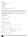
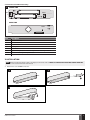
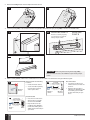
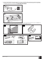
EWD2 WIRELESS MAGNETIC DOOR CONTACT/ SHOCK SENSOR/FLOOD SENSOR User manual v1.6 Compatible with: • ESIM264 v7.14.03 and up + EWT1 v16.18 and up. • ESIM364 v02.06.05 and up. • EPIR2 v01.01.12 and up. • EPIR3 v01.00.02 and up Main features: • Built-in shock sensor • 2 wireless zones • Available zone modes: magnetic door contact, shock sensor, flood sensor, digital sensor • 2 built-in tamper switches: on the front and on the back of the PCB • Bult-in temperature sensor EWD2 is a wireless device intended to secure doors, windows or any other opening/clsoing mechanisms. In addition, the device comes equiped with a built-in shock sensor for vibration detection, an on-board zone terminal designed for external digital sensor or flood sensor connection and 2 built-in tamper switches for EWD2 sabotage detection. In order to start using EWD2, it has to be paired with ELDES alarm system using ELDES Configuration Tool software or by sending a corresponding SMS text message to ELDES alarm system. ESIM264, EPIR2 and EPIR3 alarm systems support up to 16 EWD2 devices, while ESIM364 - up to 32 EWD2 devices. The maximum wireless connection range is 150m (492.13ft) (in open areas). NOTE: For complete information on device operation with ELDES alarm system, please refer to ELDES alarm system installation manual located at www.eldes.lt/download 1.CONTENTS OF PACK ItemQuantity 1. EWD2....................................................... 1 2. Magnet.................................................... 1 3. 1,5V Alkaline AAAA type batteries.... 2 4. Screws.................................................... 4 5. User manual........................................... 1 6. Double-sided adhesive tape............... 2 2. TECHNICAL SPECIFICATIONS 2.1. Electrical and Mechanical Characteristics Batteries����������������������������������������������������������� 1,5V Alkaline AAAA type, LR8D425 (IEC) / 25A (ANSI/NEDA) Number of batteries��������������������������������������� 2 Battery operation time ��������������������������������� ~18 months* Wireless band�������������������������������������������������� ISM868/ISM915 Wireless communication range ������������������� Up to 30m (98.43ft) in premises; up to 150m (492.13ft) in open areas Range of operating temperatures �������������� -20…+55 °C (-4... +131°F) Humidity ���������������������������������������������������������� 0-90% RH @ 0... +40°C (0-90% RH @ +32... +104°F) (non-condensing) EWD2 dimensions ������������������������������������������ 102x22x19mm (4.01x0.87x0.75in) Magnet dimensions���������������������������������������� 47x17x10mm (1.85x0.67x0.39in) Compatible with alarm systems ������������������ ELDES wireless * The operation time might vary in different conditions. 2 EN EWD2 Manual v1.6 2.2 Main Unit and LED Functionality 1 FRONT SIDE + Z - TAMP1 + COM RESET LED DETECT BACK SIDE TAMP2 DETECT Unit Description COM Common terminal Z Zone terminal TAMP1 Tamper switch +/- Battery slots DETECT Reed switch LED Light-emitting diode for indication of parameter restoring to default RESET Button for restoring default parameters TAMP2 Tamper switch 3.INSTALLATION NOTE: Before installing the wireless device, we highly recommend to refer to RADIO SYSTEM INSTALLATION AND SIGNAL PENETRATION manual located at www.eldes.lt/download 1. Remove the cover of EWD2 enclosure. 2 3 4 EWD2 Manual v1.6 EN 3 2. Remove the PCB (printed-circuit-board) from the enclosure. 5 6 3. Screw in (see fig.#8A) or attach the enclosure using double-sided adhesive tape (see fig.#8B) to the door or window frame. 8A 7 MOUNTING POINT A Ensure to screw in properly for supervision of the back side by tamper switch MOUNTING POINT B 20 mm max 8B ATTENTION: When using this mounting method (fig. #8B), the back side of the enclosure will NOT be supervised by tamper switch. 4. When installing EWD2, follow the recommendations for the installation to achieve the strongest wireless signal: Never install in the following locations: 9 Wireless device 11 Wireless device EN • inside the metal cabinet 0,5 to 30m (1.64 to 98.43ft) inside the building • closer than 20cm (7.87in) from the metal surface and/or power lines 0,5 to 150m (1.64 to 492.13ft) in open areas Wireless device Wireless antenna Recommended: • face the front side of the wireless device towards the antenna. • keep the distance: 0,5 to 30m (1.64 to 98.43ft) inside the building, 0,5 to 150m (1.64 to 492.13ft) in open areas Recommended: 0.5 m to 30 m (1.64 to 98.43ft) inside the building • face the front side of the wireless device towards the front side of EPIR3 0.5 m to 150 m (1.64 to 492.13ft) in open areas 4 10 EPIR3 • keep the distance: 0,5 to 30m (1.64 to 98.43ft) inside the building, 0,5 to 150m (1.64 to 492.13ft) in open areas EWD2 Manual v1.6 5. Wire up the external digital sensor (if any) or flood sensor (if any) to Z and COM terminals, otherwise do not perform any wiring. If flood sensor EFS1, which is compatible with EWD2, is to be wired, please refer to the following wiring diagram and configure EWD2 using ELDES Configuration Tool software (see 4. EWD2 ZONES AND TAMPERS). 12 COM EFS1 white red 6. Z EWD2 Insert the PCB back into the enclosure 13 7. Open the magnet enclosure and screw in (see fig.#16A) or attach the magnet using double-sided adhesive tape (see fig.#16B) to the doors or window and ensure that the magnet is fixed at the same height as the EWD2 reed switch. 14 15 10mm (0.4in) max 16A EWD2 Manual v1.6 16B EN 5 8. Remove the plastic tab inserted between one of the battery terminals and battery slots of EWD2. 17 9. Close EWD2 enclosure. DO NOT use any tools for this action. 18 ATTENTION: DO NOT attempt to close EWD2 enclosure the other way round, otherwise you might break it. 10. Pair the device with the alarm system using ELDES Configuration Tool software. Open Wireless Device Management section and enter a 8-digit wireless device ID located on the EWD2 enclosure and press Add button. The device can also be paired by sending a corresponding command via SMS text message. For more details, please, refer to the software‘s HELP section and ELDES alarm system installation manual. 19 11. Upon the successful pairing process, the message indicated next to EWD2 device icon will turn to CONNECTED. If the attempt to pair is unsuccessful, try to move EWD2 closer to the ELDES alarm system and pair anew. 12. EWD2 is ready for use. ATTENTION: Ensure that EWD2 device is properly fixed to the wall and the Mounting Point B portrayed in fig. #8A is properly screwed in. Otherwise, the tamper switch will NOT supervise the back side of EWD2 enclosure (see also 4. EWD2 ZONES AND TAMPERS). NOTE: If you are unable to pair the wireless device, please restore the parameters of the wireless device to default and try again (see chapter 7. RESTORING DEFAULT PARAMETERS). 6 EN EWD2 Manual v1.6 4. EWD2 ZONES AND TAMPERS Upon successful EWD2 device pairing process, the system adds 2 wireless Instant-type zones. The wireless zones can be set up to operate under one of the following modes each: • • Zone 1: • Magnetic door contact – Designed for causing an alarm (by default) if doors/windows are opened when the system is armed. • External sensor – Designed for causing an alarm (by default) if the wired digital sensor, connected to Z and COM terminals, is triggered when the system is armed. This mode does NOT operate with Flood sensor mode on Zone 2 simultaneously. Zone 2: • Shock sensor – Designed for causing an alarm (by default) if the built-in shock sensor is triggered. • Flood sensor – Designed for causing an alarm (by default) if a flood sensor EFS1, connected to Z and COM terminals, is triggered. This mode does NOT operate with External sensor mode on Zone 1 simultaneously. Possible zone mode combinations: • Zone 1: Magnetic door contact + Zone 2: Shock sensor • Zone 1: Magnetic door contact + Zone 2: Flood sensor • Zone 1: External Sensor + Zone 2: Shock sensor • Zone 1: Magnetic door contact + Zone2: N/A • Zone 1: External Sensor + Zone2: N/A • Zone 1: N/A + Zone 2: Shock sensor • Zone 1: N/A + Zone 2: Flood sensor NOTE: Flood sensor mode is not supported when EWD2 is used with ESIM264 alarm system. In case of tamper violation, the alarm is caused regardless of system being armed or disarmed. There are 2 ways to detect tamper violation on EWD2: • By tamper switch. EWD2 comes equipped with 2 built-in tamper switches intended for enclosure supervision: • one located on the front side of the PCB supervising the front cover in case it is illegally opened (see fig. #1). • the other one located on back of the PCB supervising the back side of the enclosure in case the EWD2 is illegally detached from the wall (see fig. #1). Once the enclosure of EWD2 is tampered, the tamper switch will become triggered. This action will be followed by alarm, resulting in sending an SMS text message and/or phone call to the user. The SMS text message contains the violated tamper name. • By wireless connection loss. The wireless connection loss between EWD2 and ELDES alarm system leads to alarm. The system identifies this event as a tamper violation and sends alarm by SMS text message and phone call to the user (-s) by default. The SMS text message contains the wireless device model, wireless ID code and tamper name. The user will also be notified by SMS text message as soon as the wireless signal is restored. ATTENTION: The tamper will not operate if both wireless zones are disabled. For more details on EWD2 zone and tamper configuration, please refer to ELDES Configuration Tool software's HELP section. EWD2 Manual v1.6 EN 7 5.TEMPERATURE SENSOR The device comes equipped with a built-in temperature sensor allowing to monitor the temperature of the area surrounding EWD2 device. When using the with EPIR3 alarm system, you may set the MIN and MAX temperature thresholds ranging from -20°C to +55°C resulting in SMS text message delivery to the listed user phone number once exceeded. The accuracy of temperature measurement is +/-1°C. 6. BATTERY REPLACEMENT 1. Open EWD2 enclosure. 2. Remove both old batteries from the battery slots. 3. Insert the 2 new 1,5V Alkaline AAAA type batteries according to the appropriate battery slot positive/negative terminals indicated on the PCB of EWD2. 4. Batteries replaced. See 3. INSTALLATION for more details. ATTENTION: Only 1,5V Alkaline AAAA type batteries can be used. Install only new, high quality and unexpired batteries. Do not mix the old batteries with the new ones. ATTENTION: At least 1 battery must be removed if the device is not in use. ATTENTION: In order to avoid fire or explosion hazards, the system must be used only with approved battery. Special care must be taken when connecting positive and negative battery terminals. Dispose old batteries only into special collection sites. Do not charge, disassemble, heat or incinerate old batteries. ATTENTION: The system sends an SMS text message to the listed user phone number as soon as the battery level runs below 5%. ATTENTION: The battery status can be monitored in real-time using ELDES Configuration Tool software. 7.RESTORING DEFAULT PARAMETERS 1. Remove any battery from EWD2. 2. Press and hold the RESET button. 3. Insert the battery back to EWD2. 4. Hold the RESET button until LED indicator provides several short flashes. 5. Release the RESET button. 6. Parameters restored to default. 8.ADDITIONAL INFORMATION Limited Liability The buyer must agree that the system will reduce the risk of fire, theft, burglary or other dangers but does not guarantee against such events. “ELDES UAB” will not take any responsibility regarding personal or property or revenue loss while using the system. “ELDES UAB” liability according to local laws does not exceed value of the purchased system. “ELDES UAB” is not affiliated with any of the cellular providers therefore is not responsible for the quality of cellular service. Manufacturer Warranty The system carries a 24-month warranty by the manufacturer “ELDES UAB”. Warranty period starts from the day the system has been purchased by the end user. The warranty is valid only if the system has been used as intended, following all guidelines listed in the manual and within specified operating conditions. Receipt must be kept as a proof of purchase date. The warranty is voided if the system has been exposed to mechanical impact, chemicals, high humidity, fluids, corrosive and hazardous environment or other force majeure factors. SAFETY INSTRUCTIONS Please read and follow these safety guidelines to safeguard yourself and others: • DO NOT use the system where it can interfere with other devices - such as medical devices • DO NOT use the system in hazardous environments • DO NOT expose the system to high humidity, chemical environments or mechanical impact • DO NOT attempt to repair the system yourself - any repairs must be carried out by fully qualified personnel only 8 EN EWD2 Manual v1.6 The WEEE (Waste Electrical and Electronic Equipment) marking on this product (see left) or its documentation indicates that the product must not be disposed of together with household waste. To prevent possible harm to human health and/or the environment, the product must be disposed on in an approved and environmentally safe recycling process. For further information on how to dispose of this product correctly, contact the system supplier, or the local authority responsible for waste disposal in your area. Copyright © “ELDES UAB”, 2014. All rights reserved It is strictly forbidden to copy and distribute information in this document or pass to a third party without an advanced written authorization from “ELDES UAB”. “ELDES UAB” reserves the right to update or modify this document and/or related products without a warning. Hereby, “ELDES UAB” declares that the wireless door contact/shock sensor/flood sensor EWD2 in compliance with the essential requirements and other relevant provisions of Directive 1999/5/EC. The declaration of conformity may be consulted at www.eldes.lt. EWD2 Manual v1.6 EN 9 Made in the European Union www.eldes.lt